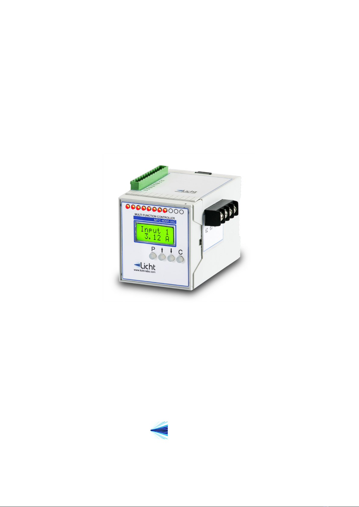
Licht http://www.licht-labs.com
Rev. A1 (20–05–09) MFC-400/I-IAC and I-IDC Technical Manual 6
Parameter:Format
Options: 8N1, 8E1, 8O1, 8N2.
Description: symbol transmission format, where:
◦8N1: 8 data bits, no parity, 1 stop bit.
◦8E1: 8 data bits, even parity, 1 stop bit.
◦8O1: 8 data bits, odd parity, 1 stop bit.
◦8N2: 8 data bits, no parity, 2 stop bits.
Parameter:Address
Options: 1 to 247.
Description: MODBUS address for the MFC-400/I-IAC or MFC-400/I-IDC.
4.4 DNP3 protocol (option)
Parameter:Baud Rate
Options: 9600, 19200, 38400, 57600, 115200 bps.
Description: baud rate for the RS-485 link.
Parameter:Format
Options: 8N1, 8E1, 8O1, 8N2.
Description: symbol transmission format, where:
◦8N1: 8 data bits, no parity, 1 stop bit.
◦8E1: 8 data bits, even parity, 1 stop bit.
◦8O1: 8 data bits, odd parity, 1 stop bit.
◦8N2: 8 data bits, no parity, 2 stop bits.
Parameter:Address
Options: 0x0000 to 0xFFEF.
Description: DNP3 outstation address in hexadecimal notation.
Parameter:Application Layer Confirmation
Options: Only when transmitting events or multi-fragment responses, Always.
Description: Selects when the MFC-400 outstation should request application layer
confirmations.
Parameter:Maximum Inter-Octet Gap
Options: 2 to 100 ms.