Lietz/Sokkisha SET3 User manual

,:~ ::.:~::":~'''- ~0V
''',

~
~
~
~
~
r
~
la
la
~
r~
~
CONTENTS
1. PARTS OF THE INSTRUMENT .................. 1
~ FEATURES.................................. 4
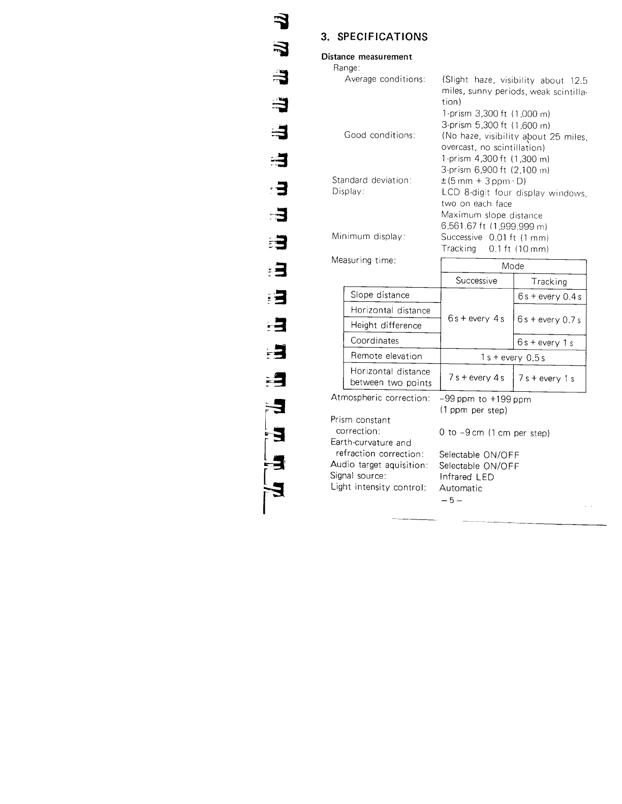
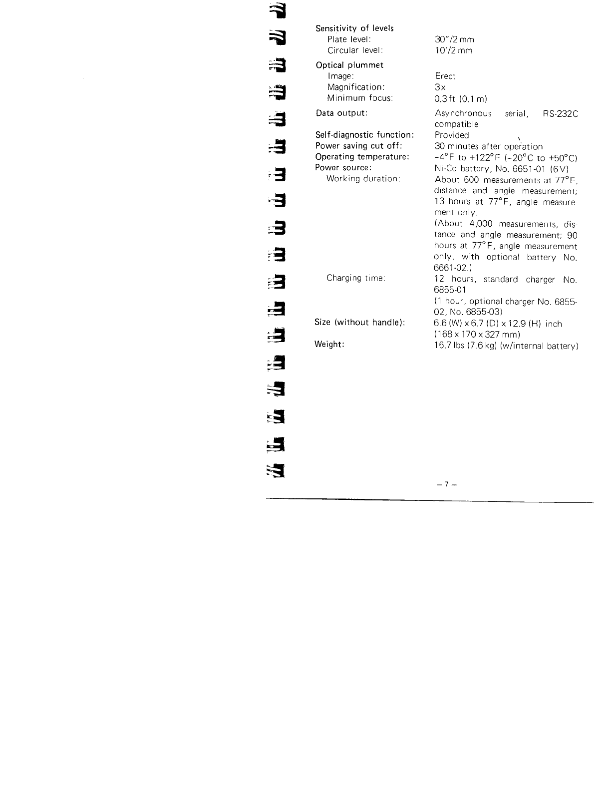
3. SPECIFICATIONS. . . . . . . . . . . . . . . . . . . . . . . . . . . . .. 5
4. STANDARD EQUIPMENT. . . . . . . . . . . . . . . . . .. . . .. 8
5. ROUND OUT YOUR LIETZ EDM SYSTEM WITH
THESE ACCESSORIES ......................... 9
6. POWER SUPPLIES.... ........ .. .. ..... .. .. .... 14
7. DISPLAY SYMBOLS .......................... 16
8. KEY FUNCTIONS ............................. 17
9. INTERNAL SWITCHES ...............,..... 20
10. OPERATION... . . . . . . . . . . . . . . . . . . . . . .. . . .. . .. 21
10.1 PREPARATION FOR ANGLE MEASUREMENT 21
10.1.1 Battery, No. 6651-01: Mounting and check 21
10.1.2 Compensation of zenith angle ........... 22
10.1.3 Centering the SET3 by adjusting tripOd leg
length ............................... 23
10.1.4 Focusing .......................... 23
10.2 ANGLE MEASUREMENT. . . . . . . . . . . . . . . . . .. 24
10.2.1 Automatically indexing vertical circle ...... 24
10.2.2 Angle measurement. . . . . . . . . . . . . . . . . . . " 25
10.2.3 Setting the horizontal circle to a required
value .. . . . . . . . . . . . . . . . . . . . . . . . . . . . . .. 26
10.2.4 Repetition of angles.. . . . .. . .... . . 27
10.3 PREPARATION FOR DISTANCE
MEASUREMENT. . . . . . . . . . . . . . . . . . . 29
10.3.1 Prism constant correction . . . . . . . . . . 29
10.3.2 Atmospheric correction .............. 29
10.3.3 Earth-curvature and refraction correction 32
10.3.4 Prism sighting ................ . 33
10.3.5 Mode selection ...................... 34
lOA DISTANCE MEASUREMENT . . . . . . . . 35
10.4.1 Angle and distance measurement . . . . . . . 35
10.42 Measurement of coordinates. . . . . . . . . . 38
10.43 Stake-out measurement .................. 40
10.4.4 Remote elevation measurement ............ 44
10.4.5 MeaslJrement of horizontal distance between
two target points ....................... 46
11. SELF DIAGNOSIS ............................. 47
12. OPTIONAL ACCESSORIES. . . . . . . . . . . . . . . . . . . .. 49
12.1 DIAGONAL EYEPIECE DE15.. . . . . .... . .. . . .. 49
12.2 ELECTRONIC FIELD BOOK SDR2 ......... . . . 49
12.3 INTERFACE IF1A FOR THE HP-41CV .........50
1204 DATA OUTPUT CABLE DOCl . . . . . . . . . . . . . . . . 50

13. CHECKS AND ADJUSTMENTS .................. 51
13.1 ANGLE MEASURING FUNCTION. . . .. . .. .. . . . 51
13.1. Plate level ................. ..... . .. . 51
13.1.2 Circu lar level . . . . . . . . . . . . . . . . . . . . . . . . . . . 53
13.1.3 I ndex error of the ti It angle sensor ......... 53
13.1.4 Reticle ............................... 55
13.1.5 Perpendicularity of the reticle to the
horizontal axis ......................... 58
13.1.6 Coincidence of the distance measuring axis
with the reticle. . . . . . . . . . . . . . . . . . . . . . . . . 59
131.7 Optical plummet........................ 60
13.2 DISTANCE MEASURING FUNCTION. .. . . .. . .. 61
13.2.1 Check flow chart . . . . . .. .......... 61
13.2.2 Additive distance constant ............... . 62
14. FOR ANGLE MEASUREMENT OF THE HIGHEST
ACCURACY .................................. 64
14.1 LEVELING BY REFERRING TO THE DISPLAY. 64
14.2 MANUALLY INDEXING VERTICAL CIRCLE
BY Vl, V2 ................ . . . . . . . . . . . . . . . . 67
15. FOR DISTANCE MEASUREMENT OF THE
HIGHEST ACCURACY. . . . . . . . . . . . . . . . . . . . . . . . . . 69
15.1 ACCURACY OF MEASUREMENT OF
ATMOSPHERIC CONDITIONS. . . . . . . . . . . . . . . . 69
15.2 TO OBTAIN THE ATMOSPHERIC PRESSURE... 69
16. PRECAUTIONS AND MAINTENANCE. . . . . . . . . . . . . 71
16.1 PRECAUTIONS............................ 71
16.2 MAl NTENANCE . . . . . . . . . . . . . . . . . . . . . . . . . . . . 72
17. ATMOSPHERIC CORRECTION CHARTS. . . . . . . . . . . 73
18. INDEX ...................................... 75
Tribrach clamp
lock ing screw
IMPORTANT
When the new SET3 is received, the tribrach clamp is fixed
with a screw. Loosen it and leave it loose.
I.
I
1
1
I
1
E
G
~
I
~
J
: '-.'R#~~/;~'!;.:(

~
~
~
~
~
:a
a
g
s
8
a
a
~
~
~
e
~
~
1. PARTS OF THE INSTRUMENT
--0
tD
4D
æ
/"0
æ
4l~-
~-_.
ID- "
Fig. 1.1
o Handle
8 Handle securing screw
e Instrument height mark
o I nterna I switch cover
o Display
o Lower clamp
8 Lower fine motion screw
(! Tribrach clamp
o Circular level adjusting
screw
lI Circular level
æ Base plate
æ Leveling screw
æ Tribrach
æ Circle positioning ring
æ Keyboard
~ Prism constant cover
4f Objective lens
-1 -
- - -",.

,
~
æit!
ID ~
w
I
mj
~~
~f1
~
W~æ
~æ ~
'ó
:;,'
Fig. 1.2
4E Tubular compass slot æHorizontal fine motion ..,
æBattery screw l
WSensor index adjustment WData output connector
cover øExternal power source
fD Optical plummet focusing connector
ring WPlate level
~Optical plummet eyepiece WPlate level adjusting screw
~Power switch ~Vertical clamp
ai Horizontal clamp mVertical fine motion screw
-2 -

~
~
~
~
~
~
;:-g
. .:
. WI
~
:-3
~3
~3
~
~
~
~
~
~
~
r
Kl
Fig. 1.3
~ Peep sight
Kj Telescope reticle adjustment
cover
K- Telescope plunging knob
æ Return signal audio switch
~ Measureltrack switch
ø ppm switch
K1 Return signal lamp
Kl Telescope eyepiece
CD Telescope focusing ring
-3 -

2. FEATURES
· HOlizontal angle, zenith angle, slope distance, horizontal
distance, height difference, N- and E-coordinates are displayed
by key operation.
· Horizontal distance between two prism points and remote
measurement of objects above and below a prism point are
automatically calculated. A stake-out function by bearing and
distance and N- and E-coordinates is standard.
· Self-diagnostic function. If, for any reason, the SET3 is not
functioning correctly during use, an error code is displayed.
· Angle lesolution can be set to 1" or 5".
· The tilt angle of the vertical axis can be measured by the
intemal sensor and displayed. By referring to the display, the
SET3 can be leveled. The zenith angle is automatically com-
pensated by the. ti It sensor and the compensated angle dis-
played.
· Hmizontal circle can be set to zero in any direction.
· The SET3 automatically switches off 30 minutes after the last
operation to save battery power,
· A RS-232C data-out connector is standard.
-4-
l'
I
I
1
I
i
I
"
I
$?;
,
~
i
i-r'
~

~
~
~
~
~
~
.3
~
~3
~3
~ ;;
~
~;l
~~
~
L~
b
r
r
3. SPECIFICATIONS
Distance measu rement
Range:
Average conditions:
Good conditions:
Standard deviat ion:
Display
Minimum display
Me
(Slight haze, visibility about 12.5
mi les, sunny periods, weak sci nti Ila-
tion)
1-prism 3,300 ft (1,000 ni)
3-prism 5,300ft (1,600m)
(No haze, visibility apout 25 miles,
overcast, no scintillation)
1-prism 4,300 ft (1,300 m)
3-prism 6,900 ft (2,100 ni)
:! (5 mm + 3 PPIl' D¡
LCD 8-digit fOlll displav wiridows,
two on each face
Maximum slope distarice
6,561.67 ft (1 ,999.999 m)
Successive 0.01 ft (1 mm)
Tracking 0.1 ft (10 mm)
asuring time: Mode
Successive Track ing
Slope distance 6 s + every 0.4 s
Horizontal distance 6 s + every 4 s 6s+everyO.7s
Height difference
Coordinates 6 s + every 1 s
Remote elevation 1 s + every 0,5 s
Horizontal distance 7 s + every 4 s 7 s + every 1 s
between two po i nts
Atmospheric correction:
Prism constant
correction:
Earth-curvature and
refraction correction:
Audio target aquisition:
Signal source:
Light intensity control:
-99 ppm to +199 ppm
(1 ppm per step)
o to -9 cm (1 cm per step)
Selectable ON/OFF
Selectable ON/OFF
Infrared LED
Automatic
-5 -

Angle measurement
Telescope
Length:
Aperture:
Magnification:
Resolving power:
Image:
Field of view:
Minimum focus:
Horizontal circle
Type:
Minimum display:
Vertical circle
Type
Minimum display
Accuracy
H:
V:
Automatic compensator
Type:
Minimum display:
Range of compensation:
Display
LCD 8-digit:
Range:
Measuring mode
Horizontal angle:
Vertical angle:
Measuring time:
6.7 inch (170 mm)
1.8 inch (45 mm)
30x
3"
Erect
1 °30' (26 ft/l ,000 ft)
4.3 ft (1.3 m)
Incremental
1"
I ncremental with 0 index
1"
Standard deviation of mean of
measurement taken in positions VL
and V2
4"
5"
Selectable ON/OFF
Liquid
1"
:13'
Four display windows, two each
face
-1,999°59'59" to 1 ,999°59'59"
Right/Left/Repetition of angles
Zenith 0° or Horizontal 0° or
Horizontal 0° :190°
Less than 0.5 s
-6-
1
i
I
i
I
*
,
I
i

~
~
~
~
~
::
:-
..~
~
::3
:-3
~;i
~
~
~~
~
~.~
~
~
Sensitivity of levels
Plate level:
Circular level:
Optical plummet
Image:
Magnification:
Minimum focus:
Data output:
Self-diagnostic function:
Power saving cut off:
Operating temperature:
Power source:
Working duration:
Charging time:
Size (without handle):
Weight:
30" 12 mm
10'/2 mm
Erect
3x
0.3 ft (0.1 m)
Asynchronous serial, RS-232C
compatible
Provided \
30 minutes after operation
-4°F to +122°F (-20°C to +50°C)
Ni-Cd battery, No. 6651-01 (6V)
About 600 measurements at n° F,
distance and angle measurement;
13 hours at n° F, ang Ie measure-
ment only.
(About 4,000 measurements, dis-
tance and angle measurement; 90
hours at 7r F, angle measurement
on Iy, with optional battery No.
6661-02.)
12 hours, standard charger No.
6855-01
(1 hour, optional charger No. 6855-
02, No. 6855-03)
6.6 (W) x 6.7 (D) x 12.9 (H) inch
(168x170x327mm)
16.7 Ibs (7.6 kg) (w/internal battery)
-7 -

4. STANDARD EQUIPMENT
~
SET3 main unit. . . . . . . . .
I nternal battery,
NO.6651-01 .......... 2
Battery charger,
No. 6855~1 ..........
Battery charging adaptor,
No. 6660-00 .. . . . . .
Tubular compass, CP7
(accuracy::tl°) .......
Lens cap ... . . . . . . . . . . .
Lens hood . . . . . . . . . . . . .
Vinyl cover. . . . . . . . . . . .
I
I
,
I
I
3
I
I
~
I
f
i
--_.J
Fig, 4,1
Plumb bob ............ 1
Tool pouch. . . . . . . . . . .. 1
Screwdriver .. . . . . . . . , .. 1
Lens brush ............ 1
Adjusting pin ....,..... 2
Cleaning cloth. . . . . . . , .. 1
Atmospheric correction
chart .. . . . . . . . . . . . . . .
Operator's manual. . . , . . .
Field guide ............
Carrying case, SC46 .....
-8 -
,

ê
~
~
5. ROUND OUT YOUR LIETZ EDM SYSTEM WITH
THESE ACCESSORIES
POL yeAR BONA TE R ETRO
PRISMS
For use with all EDM systems re-
commending round retro prisms.
Mounting system allows choice of
-30 mm or 0 offset. Prisms her-
metically sealed to prevent con-
tamination of reflective surfaces.
Prisms interchangeable on all
mou nts.
TRIPLE NON-TILTING PRISM
ASSEMBL Y
w/lens cover
No. 7265-31
TRIPLE TILTING PRISM
ASSEMBL Y
w/lens cover, similar to 7265-31,
prism mount rotates 3600
No. 7266-31
SINGLE TILTING PRISM
ASSEMBL Y
w/lens cover, rotates 3600
No. 7266-32
PRISM ONLY IN MOUNTING
CAN
w/lens cover, hermetically sealed
No. 7266-35
ACCESSORIES FOR PRISMS
NINE PRISM ADAPTOR
Joins 7266-31 and two 7265-31.
PEEP SIGHT
Fits on 7265 and 7266 mounts for
easier aiming.
No. 7266.30
TARGET
Fits 7266.31 triple prism assembly,
ideal for coaxial total stations.
No. 7266-41
TARGET
Fits 7266-32 single prism assembly.
No. 7266-46
RETRO PRISM CARRYING
CASES
Vinyl plastic carrying case w/full
zipper for easy access and storage.
Inside padded. Exterior is bright
international orange color. Sizes for
single or triple retro prisms.
No. 7270-50 Triple retro prisms
No. 7270-52 Single retro prisms
-9 -

LIETZ SIGHTING TARGET SET
No. 7311-45 contains one each of
the following:
7269-34 Single Round Tilting
Prism Mount
7270-35 Round Prism wlcontainer
7270-29 Sigh ting Target for Retro
Prism
7311-38 Tribrach Adaptor w/re-
movable, rotatable center
7311-35 Optical Plummet Tribrach
Â
_".,
A
~
I
..
TRIBRACHS AND ADAPTORS
OPTICAL PLUMMET TRIBRACH
For' precision piumbing. Has circu-
lar level vial with sensitivity of 10
minutes per.2 mm.
Optical plummet focus by push-pull
slide. Range: 1.5 to 50 ft.
No. 7311-35
TRIBRACH LEVELING BASE
Same as above but without optical
plummet.
For use with Az imuth Base
(7150-41 l.
No.7311-34
..f........~... .... ~~.
~-_. -
)...-~
. .
-10 -
t.
I
;.\
-;
I
I
I
I
~
i
i
,
I
l
I

;.
~
~
~
~
a
a
9
8
a
8
~
~
~
~
s
FI
~
TRIBRACH ADAPTOR
Allows installation of retro prism or
other accessories into tribrach.
5/8 x 11 thread.
No. 7311-37
.
TRIBRACH ADAPTOR
Similar to above except with re-
movable. rotatable center.
No. 7311-38
tI
..
TRIBRACH ADAPTOR
Allows easy mounting of 7266-31
and other prism with bayonet type
mount in tribrachs.
No. 7311-40
OPTICAL PLUMMET TRIBRACH
ADAPTOR
Similar to above but with rotating
vertical axis and optical plummet
for precise positioning of prisms in
tribrachs without optical plummet.
No.7311-41
TRAVERSE SET
WITH CARRYING CASE, For
precise triangulation surveys, day or
night.
No. 7312-45 Set contains two each
of the following:
7311-35 Optical Plummet Tribrachs
7311-37 Tribrach adaptors
7312-39 Illumination units
7312-40 Rotatable sighting targets
mounted on a base
~
m_~1-
, ,~-
, il
--~ Exploded
view
.
LARGE TARGET
Large target 8-1/4" x 11-3/4" at-
taches to regular target (No. 7312-
40) to provide increased sighting
range.
No, 7312-42
-11 -
,,-..,,'..

RANG E PLUMBING POLE
Aluminum tubing and brass fittings
with hardened steel point. Height
adjusts from 54" to 100". Upper
section mounting stud accepts single
or triple retro prisms; locking disc
prevents prism rotation. Includes
replaceable rod level (No. 8071-90).
No. 7270-48
-= .. -l
TELESCOPING RANGE
PLUMBING POLE
Ideal for EDM and traverse
work. Made of quality alumi-
num tubing with brass fittings
and hardened steel po in t.
Positive chuck style twist lock
permits height adjustment
from 54" to 100". Replace-
able rod level (No. 8071-901
and point (No. 8078-50),
Upper section has 5/8 x 11
mounting stud to accept single
or triple retro prisms.
No. 72 70-46
TRIPODS
Tripods recommended for use with
these accessories (not included in
price):
No. 7512-52 Wide Frame,
Extension Leg (wood)
No. 7536-75 Wide Frame,
Extension Leg (aluminum)
RANGE POLE SUPPORT
Made with metal center castings,
rustproof steel legs w/one adjustable
(hinged) leg for uneven ground.
No. 8078-90
/
RANGE POLE TRIPOD
Heavy-duty. Made with metal
center castings. Rustproof steel legs,
adjustable for uneven ground.
No. 8078-95
- 12-
1
..
t
.
~
,
11
l
1
!
i
~
I
fI
I
¡
~
,
..J

:;
~
~
~
~
:a
~3
~
~
~
¡a
~
~
~
~
~;
~
I:
~
POCKET THERMOMETER
Refillable metal case. Mercury
filled. Range: _30° to 120°F in 2°
incremen ts.
No. 8006- 12
~~
BAROMETER/AL TIMETER
with watch-type case.
English-Range ° to 15,000 ft.
No. 8001-70
(Î,....,.,."
;:," .)
~" ~ . ~
-13 -

6. POWER SUPPLIES
The SET3 can be operated with the following combinations:
. Standard set.
Optional accessories are not
marked with an asterisk.
. SET3
Fig. 6.1
~-t9
. Internal
battery
No. 6651.01
. Battery
charging
adaptor
No. 6660.00
~ .. 12 hours charger
No. 6855-01
(120VAC)
~1 hour quick
charger
No. 6855-02
(120V AC)
ø AC power adaptor
6V . No. 6861-01
, (10010240VAC)
~1 hour cigar
lighter charger
No. 6855.03
112V DCI
o _LJ External battery
Cable 16V) tJ No. 6661.02
No. 6860.07 (7 hours use)
-14 -
~
15 hours charger
No. 6855.05
(120V ACI
Cable to
cigar lighter
No. 6860-05
Cable to car
battery
No. 6860-03
Use the SET3 only with the combinations shown here.
;;;;~~i:
No. 6860-02 fi
Note: When using the SET3 with external power supplies, it is
recommended that for the most accurate angle measure-
ments, the No. 6651-01 battery be left in place to balance
the weight on the axes.
,~
:t
l
~
,~
+
1
(1
,l,
:i
i
i,1
;ç
l
t,
~.,
I
i
I
~
,

~
~
~
~
~
Battery charging precautions
To charge the battery, use only the recommended charger,
1) Charge the battery at least once a month if it is not used for
a long time.
2) Charge the battery at a temperature between 50° F to 104° F
(10°C to 40°C),
3) Before using No. 6861-01, set the voltage selector to the
proper voltage, \
4) No. 6860-02 has a breaker switch. Normally the red mark
appears on the breaker. If not, set the red mark in place.
5) When using a car battery, make sure that the polarity is
correct,
6) Make sure that the cigar I ighter has 12 V output and that the
negative terminal is grounded.
7) When charging the battery, first connect it to the battery
charger and then connect the charger to the power supply.
Check that the battery charger light is on, If not switch
power supply off and on again until the light comes on.
8) The battery charger may become warm while charging. This
is normal.
9) Do not charge the battery for any longer than specified.
10) Store the battery in a place where the temperature is between
32° F to 104° F (O°C to 40° C).
11) Battery operating life is shortened at extreme temperatures.
-15 -

7. DISPLAY SYMBOLS
r~ Slope d ¡stance
H.~ Horizontal I
angle right IÆ Horizontal distance
H... Horizongal .Li Height difference
angle left 11.+ N~coordinate
H.~~ Horizontal angle ~+ E-coord i nate
repetItion _1-+Compensated angle
HHorizontal
angle hold 1Tilt angle
REM
Zenith angle H ...~~ 5.0 ~I~+ .. ~
V 0'"
'OOOOOOOF
I l-I ,_, '_I l-I '_I '_I l-I CD
. .
Horizontal distance
between two points
Feet
EDM power ON
Distance, angle or error code
Fig. 7.1
-16-
,t
.
l
l
-i\
I
,
I
I
-
~
-
~
;

.,
~
~
i1
a
3
;I
~
::
3
a
a
3
~
~
a
a
~.
8. KEY FUNCTIONS
SET3 has three measurement modes.
When it is switched on and the vertical circle is indexed by rotat-
ing the telescope, it is automatically in the theodolite mode.
B+ ~,~,~,
Theodolite Basic mlor ~ EDM +
mode mode Theodol ite
\mode
.Ð 4II
Fiii,8,1
Theodolite mode
Angle measurement,
SET3 accepts g, 1f, EI., II, ~, 0 or Ii keys.
Basic mode
Prism sighting, data entry and recall.
SET3 accepts all keys except g, 1f, EI, f§ or Ii keys.
EDM + Theodolite mode
Angle and distance measurement.
SET3 accepts Ii or II keys.
-17 -
Table of contents
Popular Measuring Instrument manuals by other brands

Precision Digital Corporation
Precision Digital Corporation ProtEX-MAX PD8 Series instruction manual

FM Marin
FM Marin Gobius 4 manual

R&S
R&S ESW-K58 user manual

Radiodetection
Radiodetection PCMx user guide

VOLTCRAFT
VOLTCRAFT DO-101 operating instructions

SATO KEIRYOKI
SATO KEIRYOKI 1722-00 instruction manual