Lievers HAL E User manual

OPERATION MANUAL AND PART LIST
BULLFLOAT HAL > 01/06
Lievers B.V. Holland
Postbus 103
3640 AC Mijdrecht
tel: +31 (0)297-231900
fax: +31 (0)297-231909
e-mail: [email protected]
www.lieversholland.nl
© Copyright 02-01-2006, Lievers B.V. Holland
1

HAL Operation manual
Figure 1 View of the most important components
1. Aluminium profile 7. Grip
2. Operating handle 8. On/Off-switch
3. Pitch control 9. Gasthrottle
4. Drive unit 230V/50 Hz 10. Plug
5. Drive unit 42V/200 Hz 11. Cable
6. Petrol engine
2

HAL Operation manual
GENERAL SAFETY-ASPECTS
All Lievers equipment have been tested in accordance with the strict international safety standards.
This section contains general advice and apply to several machines mentioned in this paragraph.
- Ensure that you are qualified (familiar with the contents of this manual), to operate and carry out
light maintenance-work to the machine when you are operating the machine for the first time.
- Wear safety shoes with extra protection (steel caps and anti-slip soles)
- Wear a safety helmet,safety glasses, working gloves, which do not conduct electricity and
protective clothing.
- Ensure, that all symbols on the machine, can always be clearly read.
- Do not leave any tools or parts lying around on the work floor, as this can cause accidents.
- Watch where you are going, the ground can be slippery.
- Take care that you do not injure yourself on objects, such as scaffolding and
reinforcement materials, which can be found directly or indirectly in the working area.
- Be careful when lifting and carrying the Bullfloat. Do not bend forwards when picking up the
apparatus, but bend your knees. Ensure that the working area is within your reach, sothat you do
not have to bend forward.
- When cleaning the machine, ensure that no water or cleaning detergents get into the
motorhousing.
- When the machine is not being used for longer periods of time, then it must be stored in a dry and
clean area.
- Do not only pay attention to your own safety, but also to that of your colleagues.
Regular maintenance of the machine promotes safe operation.
The following safety-aspects specifically apply to those Lievers products which are
equipped with an electrical drive unit.
- Place the wires between the electrical source and the work place in such a way, that they cannot
be damaged and your colleagues cannot trip over them.
- Do not use the machine in an explosion endangered area.
- Check that the electrical source complies with the local valid regulations. Use earthed extension
leads, when it is necessary to use extension leads.
- Use an electrical source which is provided with an earth leakage switch or attach a safety
transformer between the electrical mains and the machine.
- Ensure that the wall socket and possible connections between the extension leads are protected
against dampness.
- Do not pull the plug out of the wall socket or extension lead by its lead.
- Regularly check the connections of the supply-cable to the switch.
3

HAL Operation manual
- Check the feeder cable’s outercasing and if in use extension lead’s outercasing before you connect
the machine to the electrical mains. The outercasing may not be damaged. Replace the cable if
you cannot read the marks on the outercasing anymore.
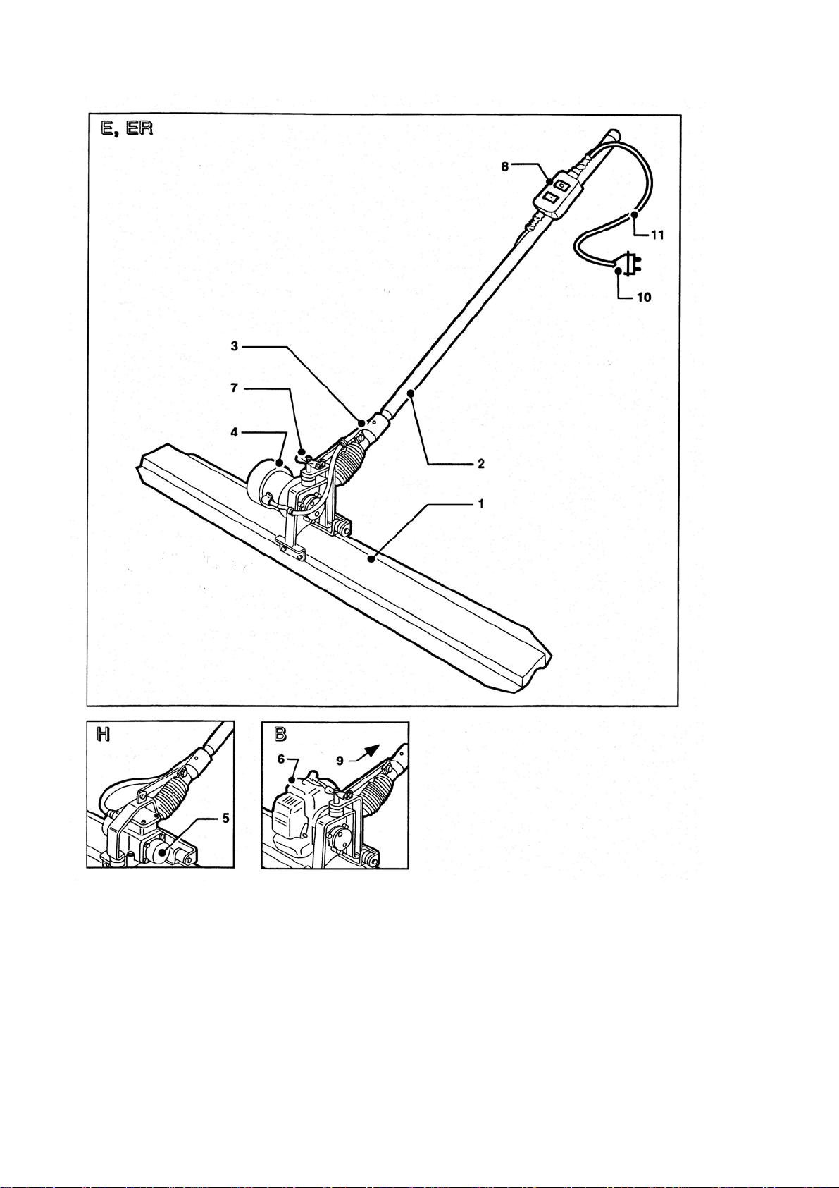
- Check the machine’s cable-connections before you connect the machine to the electrical mains.
The cables must be properly connected.
- Switch off the machine, when the electrical power cuts off. This prevents the machine from starting
suddenly when the electrical power comes on again.
- Disconnect the electrical supply to the machine, before you start to clean or maintain the machine.
- Ensure that the ventilation slots of the machine are free from dirt and moisture.
The following safety-aspects specifically apply to those Lievers products which
are equipped with a petrol-engine.
- Do not use the Bullfloat with petrol-engine indoors or in poorly ventilated places, such as pits etc.
- Make sure that there is sufficient ventilation in spaces which are surrounded by walls. Never inhale
exhaust gasses, they can damage your health and that of your colleagues.
- To avoid getting an electric shock, do not touch the high-tension cable or spark plug cap while the
engine is running.
- Check for fuel leaks before running the machine.
- Do wear working-gloves, safety glasses and protecting clothing during refueling.
- Make sure that there is sufficient ventilation during refueling.
- Refueling of fuel is only allowed after the engine has been cooled off sufficiently.
- Refueling of fuel , while the engine is hot, might lead to a very dangerous situation.
It is strictly forbidden to refuel :
* in the direct vicinity of open fire or other flammable materials,
* while smoking cigarettes etc.
* in explosion endangered spaces.
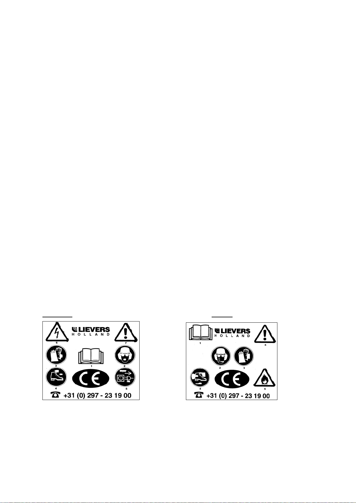
Explanation of the used safety symbols
HAL E/ER HAL B
1 Please read the instructionbook
2 Safety glasses, safety helmet and ear protection compulsory.
3 Working gloves compulsory. (vibration Isolating work Glove with GELFÔM)
4 Safety shoes with extra protection compulsory.
5 Before opening the motorhousing remove the plug from the mains/ Inflammable material
6 Dangerous electrical voltage/ Careful, DANGER!
7 Careful, DANGER!!
TIP: If the safety aspects are not clear to you, then please contact the manufacturer for
further information: Lievers Holland. Telephone: + 31 297 231900; Telefax: + 31 297 231909
4

HAL Operation manual
TECHNICAL DATA HAL E, ER, H en B (Honda)
HAL E, ER
(230V/50-60Hz)
*(115V/50-60Hz)
HAL H
(42V/200Hz)
HAL B Honda
(4-stroke petrol engine)
Voltage
Capacity
Revolutions
Centr. force
Mass
Fuel
Insulation
Sound press.
level ISO6081
** Value of
accelaration
Comfort.exposure
Execution
230V/1-fase/50-60Hz
350 Watt
8.500 rpm
1800 Newton
2.0m 15 Kg
-------------
IP54, splash proof
Double insulated
76dB(A)
at operator’s place
2,46m/s²
8,3hr Max 33hr a day
Portable
42V/3-fase/200Hz
200 Watt
6.000 rpm
1500 Newton
2.0m 15 Kg
-------------
IP54, splash proof
65dB(A)
2,7m/s²
7hr Max 26hr a day
Portable
-------------
0,81Kw (1,1 Hp)
9.000 rpm
1800 Newton
2.0m 15 Kg
unleaded petrol (95)
------------
80dB(A)
3,89m/s²
3,3hr Max 13,2hr a day
Portable
*On request
** The weighted effective value of accelaration,determined according to ISO 5349
Electrical diagram types E en
ER
Electrical diagram types H
5

HAL Operation manual
OPERATION INSTRUCTIONS
This chapter describes the use of the complete range of HAL200 bullfloats.
TIP:For the location and description of the bullfloat’s parts, which are mentioned in the
text, we refer to the illustration figure 1 on the backside of the cover.
HOW TO ASSEMBLE THE HAL 200 BULLFLOAT.
When delivered the bullfloat is not ready for use.You only have to carry out the following
procedures.
1 Connect the switch ( an ON/OFF-switch, an electronic speed regulator, or a gasthrottle),
to the operating handle by means of the bracket and the butterfly nut.Now lock the bracket
by tightning the butterfly nut.
2 Stick the operating handle into the shaft of the motorunit-frame.Make sure that the operating
handle is locked in the proper way.
Figure 2 Assembly of the controls.
HOW TO ADJUST THE TROWEL BLADE ANGLE.
Adjusting the blade pitch
Use position (1) when smoothening normal freshly poured concrete.
6

HAL Operation manual
This section describes how to operate and use the bullfloat.In the text are numbers in brackets.
These numbers are position numbers and they correspond to the numbers in the parts list of
the corresponding figures.
CAREFUL: Read the safety aspects and instructions before you switch on the apparatus.
CAREFUL: Prevent the bullfloat of sinking into the concrete.After the motor has been switched
on, immediately move the bullfloat backwards.
TIP: Before the bullfloat is brought into action, first compact the freshly poured concrete
floor with a poker-vibrator while at the same time adjust the height of the floor by
means of a laser device.
TIP: Pour concrete lanes of approx. 3 m. wide and approx. 15 m. long.You can finish this
surface in one pass without any problem.
Type of switches.
OPERATION OF THE BULLFLOAT , TYPE HAL200/E
1 Check that the bullfloat is properly assembled and make sure that the switch is in the
OFF position.
2 Place the bullfloat in the direct vicinity of where you are going to smoothen the surface of
the concrete.
3 Push the plug of the vibrating -unit’s feeder cable into the wall socket.
4 Place the bullfloat on the surface of the freshly poured concrete-floor.
5 Put the switch in the ON position.
6 Adjust the trowel blade angle.
7 Now start to smoothen the surface of the concrete-floor by moving the bullfloat backwards in
a slow but steady motion.
8 After having finished one lane of concrete, switch off the bullfloat immediately.
TIP: If the processed concrete-surface is not smooth or level enough, repeat the procedures
5,6,7 and 8 .
9 Pull the feeder cable’s plug of the bullfloat out of the wall socket.
10 After use, place the bullfloat on a dry and stable surface.
7

HAL Operation manual
OPERATION OF THE BULLFLOAT, HAL200/ER
1 Check that the bullfloat is properly assembled and that the switch is in the OFF position.
2 Put the plug of the drive-unit’s feeder cable in the wall socket.
3 Place the bullfloat in the direct vicinity of where you are going to smoothen the surface
of the concrete-floor.
4 Place the bullfloat on the surface of the freshly poured concrete, and turn the speed regulator
slowly to the required revolutions.
5 Adjust the trowel blade angle.
6 Now start to smoothen the surface of the concrete floor by moving the bullfloat backwards
in a slow but steady motion.
7 After having finished one lane of concrete, switch of the bullfloat immediately, by turning
he speed regulator’s knob to the position MINIMAL.You will hear a CLICK.
Worksituation during smoothing and compacting of the concrete floor.
Tip: if the processed concrete surface is not smooth or level enough, repeat the procedures 5,6,7 and 8
8 Pull the plug of the feeder cable out of the wall socket.
9 After use, place the bullfloat on a dry and stable surface.
OPERATION OF THE BULLFLOAT, HAL200/H
CAREFUL: Make sure that the frequency-convertor is running before connecting the bullfloat.
1 Check that the bullfloat is properly assembled and that the switch is in the OFF position.
2 Place the bullfloat in the direct vicinity of where you are going to smoothen the surface of
the concrete-floor.
3 Insert the 42V.plug into the socket of the frequency-convertor.
4 Switch-on the frequency-convertor.
5 Place the bullfloat on the freshly poured concrete.
6 Put the switch in the ON position.(PostionI)
7 Adjust the trowel blade angle.
8 Now start to smoothen the surface of the concrete by moving the bullfloat backwards in a slow
and steady motion.
9 After having finished one lane of concrete put the switch in the 0 position.
10 Disconnect the plug from the frequency-convertor.
11 After use, place the bullfloat on a dry and clean surface.
8

HAL Operation manual
Operation of the HAL bullfloat type B (petrol engine)
WARNINGS
1. Do not run the engine in a closed area. Exhaust gas contains carbon monoxide,
an odorless and deadly poison.
2. Gasoline is extremely flammable and can be explosive under certain conditions.
3. Do not smoke. Make sure the area is well ventilated and free from any source of flame
or sparks.
4. Stop engine and allow the engine to cool off before refueling.
5. Do not fill the tank so the fuel level rises into the filler neck or level surface of the
level gauge. If the tank is overfilled, heat may cause the fuel to expand and
overflow through the vents in the tankcap.Wipe off any spilled gasoline immediately.
6. Keep the engine at least 1 mtr. away from buildings, obstructions and other burnable
objects. To avoid getting an electric shock, do not touch the spark plug or spark plug
lead during engine running.To avoid a serious burn, do not touch a hot
enginemuffler.Before you service or remove parts stop engine and allow the engine
to cool.
7. Always remove the spark plug lead from sprak plug when servicing the engine to
prevent accidental starting.
Read the instruction manual of the petrol engine.
MAINTENANCE AND REPAIR.
Allthough the bullfloat has few moving parts, regular maintenance promotes a long and
trouble-free life.
WARNING!: Never use a high pressure cleaner to clean the bullfloat with an electrical- or
petrol drive unit.
LUBRICATING THE BLADE PITCH CONTROL.
Lubricate the blade pitch control , after a long periode of storage , or at least twice a year with Texaco
Multifak EP 2.
CLEANING AND SERVICING OF THE ELECTRICAL DRIVE UNIT.
WARNING!: Cut off the electrical supply to the bullfloat , before carrying out any maintenance
activities to the bullfloat.
In order to achieve a maximum cooling effect the ventilation slots of the electrical drive unit
must stay free from dirt and grease.Check them at the end of each working day.
If necessary, clean the motor with a brush or a damp cloth.
CLEANING AND SERVICING OF THE PETROL ENGINE.
In order to achieve a maximum colling effect the ventilation openings must stay free from
dirt or grease.Check them at the end of each working day.
If necessary, clean them with a brush or a damp cloth.
For a proper functioning of the carburator’s control mechanism , it is necessary to check the
carburator for concrete or dirt, each time after use.If necessary clean the control mechanism with a
brush or a damp cloth.
9

HAL Operation manual
TROUBLE-SHOOTING
Problem:The bullfloat does not vibrate in the ON position.
Cause:
Fault in the electrical connections of the feeder cable.
Solution:
Check the electrical connections to the bullfloat, switch, plug and feeder cable for breakage.
Replace the faulty part(s).
Problem:The bullfloat does not get into the required number of revolutions.
Cause:
Extensive voltage drop, due to the feeder cable being too long (longer than 25 m)
Solution:
Move the electrical source closer to the working area.
Problem: The electrical motor rotates irregularly and makes a lot of noise.
Cause:
1 The bearings are worn out, and/or
2 an electrical defect in the stator, and/or
3 a break in the feeder cable.
Solution:
1 Replace the bearings, and/or
2 replace the stator, and/or
3 repair or replace the feeder cable.
Problem: The connected and running bullfloat rotates irregularly and does not get into
the required revolutions.
Cause:
Insufficient current supply.
Solution:
Electrical supply via a safety transformer, check the distributed power from the safety
transformer.
Electrical supply via electrical mains, check the plug connections for defects.
Use an extension lead of a maximum length of 25 m. with a cross section of 2.5mm2.
Problem: the electrical motor runs irregularly.
Cause:
The carbon brushes are worn out.
Solution:
Replace the carbon brushes. (replace every 6-12 months)
Problems solving for bullfloats with petrol engine: see the enclosed engine manual, provided by the
engine supplier/producer.
Tip: if the problem you are facing is not mentioned in this list, please contact your supplier or contact
Lievers B.V. Tel +31 (0)297 231900. Fax: +31 (0)297 231909.
10

HAL Operation manual
Warranty
Your new LIEVERS “ HAL Bullfloat “ is warranted to the original purchaser for a period of one-year ( 12
months ) from the original date of purchase.
The LIEVERS warranty is against defects in design, materials and workmanship.
The following are not covered under the LIEVERS warranty:
- Damage caused by abuse, misuse, dropping or other similar damage caused by or
as a result of failure to follow assembly, operation or user maintenance instruction.
- Alterations, additions or repairs carried out by persons other than LIEVERS Products
or their recognised agents.
- The ventilation slots are not cleaned regularly,
- Unqualified personnel (not familiar with the contents of this operation manual) have
assembled or dismantled the HAL.
- The HAL has been stored in a damp environment.
- The HAL has been cleaned with a high pressure cleaner or by water jet
under high pressure.
- The HAL has been connected to a wrong voltage.
Guarantee-certificate
Bullfloat Type HAL, Nr.............
Purchase date :................
Manufacturer:
Bouwmachinefabriek Lievers B.V.
Address: Groot Mijdrechtstraat 68, Mijdrecht, The Netherlands.
EC-Declaration
EC-Declaration of agreement for machinery
(Directive 98/37/EC, Annexe II, under A)
Manufacturer: Bouwmachinefabriek Lievers B.V.
Address: Groot Mijdrechtstraat 68, Mijdrecht, The Netherlands
Hereby declares that:
The bullfloat type : HAL
complies with the regulations for the Machine Directive (No. 98/37/EC, as
lastly modified).
Complies with the following harmonized standards:
NEN – EN 292 – 1 (1994), NEN – EN 292 – 2 (1996), NEN – EN 60335 – 1 (1995),
NEN – EN 55014 (1994), NEN – EN 60204-1 (1996), NEN – EN 50144 2 11 (1996)
Done at Mijdrecht, 1 january 2004
Name: Dhr. J.F. Lievers
Function: Director.
11

HAL Operation manual
HAL type E, ER en B frame (only)
Spare parts drawing HAL E, ER en B frame (only)
12

HAL Operation manual
HAL type E, ER & B frame (only)
Index Partnumber Quantity Description
1 230010 1 Alum. profile 1.0 m.
230015 1 ,, ,, 1.5 m.
230020 1 ,, ,, 2.0 m.
230025 1 ,, ,, 2.5 m.
3 23003 1 Motor assembly bracket
4 0060 3 Rubber buffer
5 0124 5 Bolt
6 0173 2 Undulated ring
7 0093 3 nut
8 0115 2 Bolt
9 0107 2 Nut
10 0172 2 Retaining ring
11 0156 4 Washer
31 230031 1 Assembly bracker
34 0140 1 Bolt
35 0212 1 Retaining ring
36 23036 1 Grip
37 23037 1 Spacer
49 2348 3 Operating handle
50 2350 1 Pitch control
51 23051 1 Rubber sleeve
53 23053 1 Adjustable strip
54 0131 2 Bolt
56 23056 2 Spacer
58 0203 2 Lock-ring
59 23059 1 Lubricating nipple & cap
60 0133 1 Bolt
61 23061 1 Spacer
63 23063 1 Brass nut
64 0125 1 Bolt
66 23066 1 Plastic clamp
68 23068 1 Locking clip
13

HAL Operation manual
HAL type E, ER Drive unit
Spare parts drawing HAL E, ER drive unit
14

HAL Operation manual
Hal type E, ER drive-unit
Index
Partnumber Quantity Description
3A
3B
3C
20
41
42
43
45S
45R
46
47
52
53
54
55
56
57
58
59
60
61
62
63
64
2303A
2303B
2303C
2320
0521
0522
1101220240
2345S
2345R
2346
0249
1101220170
1101220200
1101220290
1101220220
1101220180
2357
2358
0248
2360
1101220230
0230
0231
0154
1
1
1
1
1
1
1
1
1
1
5
1
2
1
2
1
1
1
3
1
1
3
3
3
Ventilation ring (small)
Ventilation ring (large)
Ventilation housing
Drive unit complete
Plastic nut M20
Packing box M20
Rear-bearing
Stator
Rotor
Frontshield
Self tapping screw
Ventilator-cover
Screw
Rubber bearing support
Brush-cover
Motor-housing
Capacitor
Capacitor-clamp
Self tapping screw
Terminal-bloc
Set of brushes
Self tapping screw
Self tapping screw
Washer
15

HAL Operation manual
HAL type E, ER Drive unit& Switch
Spare parts drawing HAL E, ER Drive unit & switch
16

HAL Operation manual
Hal type, E, ER drive-unit&switch
1
2
6
7
8
10
11
12
13
14
16
20
21E
22
23
24
29
33
35
44
69E
69ER
70
71
72
73
74
75
77
78
90
91
92
93
94
95A
95B
96
97
98
99
100
101
102
103
104
105
2301N
2301N
2306
2307
2308
0155
2311N
231213
231217
0201
2314
2316
2320
0051
0052
0212
0088
0017
0086
2335
0004
2369E
2369ER
23070
23071
23072
0325
23074
0261
0099
0122
0522
0521
2392
2393
2394
2395A
2395B
2394A
2397
2398
2399
0522
2389
2391
2387
0087
0210
1
1
1
2
1
3
1
1
1
1
1
1
1
3
1
3
2
1
1
1
1
1
1
1
1
1
1
1
2
2
1
2
2
1
1
1
1
1
1
1
1
1
2
1
1
1
4
4
Excenter-housing
Excenter-shaft
Rubber seal
Adaptor-bolt (short)
Adaptor-bolt(large)
Washer
Cover&bearing (excenter .)
Excenter 1.0 - 1.5 m.
Excenter 2.0 - 2.5 m.
Lockring
Excenter-bearing
0-ring
Drive-unit
Rubber buffer
Coupling-rubber
Retaining ring M8
Capnut
10 mtr.Cable 2 x 2,5 mm2 with plug
Capnut (high)
Cable-clamp
Cable
Switch assembly bracket (E)
Switch assembly bracket (ER)
Switch housing
Rocker-switch (only)
Switch-cover
Wing-screw
Switch complete
Screw
Self-locking nut
Screw
Packing boxM20
Nut M20
Speed-regulator (only)
Switch-box (speed-regulator)
Potentiometer & switch
Knob (potentiometer)
Knob-cap
Nylon spacer
Terminal-bloc
Speed-regulator compl.(incl.bracket)
Speed-regulator compl. (excl.bracket)
Packingbox M20
Isolation plate
Aluminium protection housing for switch
Sticker on-off
Nut M6
Nylon bolt M6x12
17

HAL Operation manuel
HAL type B, Drive unit Honda & Throttle
Spare parts drawing HAL B, Drive unit Honda & throttle
18

HAL Operation manual
Hal type B petrol-drive & gas throttle
Index Part number Quantity Description
1
2
6
7
8
10
11
12
13
14
16
18
20
20A
21B
22
23
24
28
29
31
33
65
66
67
68
69B
70
71
72
73
74
75
76
77
78
79
80
81
83
84
85
86
2301N
2301N
2306B
2307
2308
0155
2311N
231213
231217
0201
2314
2316
2318N
2302666020HON
2320GX25
0055
0052
0172
0088
2328
0153
0099
0086
2365
0089
0123
0154
2369B
2302666700
2371
2372
0325
2383C
2375
2376
0270
0122
0123
2644
0091
2383
0263
2321H
2643
1
1
1
2
1
3
1
1
1
1
1
1
1
1
1
3
1
3
2
3
2
2
1
2
1
1
3
1
1
1
1
1
1
1
1
1
1
4
1
1
1
1
1
1
Excenter-housing
Excenter-shaft
Rubber seal
Adaptor-bolt (short)
Adaptor-bolt(large)
Washer
Cover&bearing (excenter hs.)
Excenter 1.0 - 1.5 m.
Excenter 2.0 - 2.5 m.
Lock ring
Excenter-bearing
0-ring
Engine bracket
Petrol engine
Engine adaptor Honda GX-25
Rubber buffer
Coupling-rubber
Retaining ring M8
Capnut
Spacer
Washer M5
Selflocking nut M5
Capnut (high)
Fibber-ring
Nut M6
Bolt M6x14
Retaining-ring M6
Gas handle & bracket complete incl. 65, 66, 67, 68, 70, 73
Gas handle complete incl. 65,66,67,68
Throttle-cable (outer)
Throttle-cable (inner)
Wing-screw
Spring at carburettor
Assembly-bracket
Throttle-cable stopper
Hex. bolt M5x16
Screw M6x8
Bolt M6x14
Throttle-cable adjustment bolt
Nut M6
Retaining-spring gas handle
Hex-bolt M5x12
Switch-bracket
Kill-switch engine
Spare parts HAL B drive-unit and gas throttle.
19

HAL Type H 42V/200Hz Frame & Drive-unit and switch
HAL type H (42v/200Hz)
Spare parts drawing HAL-200 type H
20
This manual suits for next models
2
Table of contents
Other Lievers Trowel manuals