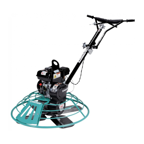
Lievers LAP 45 User manual

2Operation Manual LAP 45, revision 3.1: 16-05-2018
TABLE OF CONTENTS
1. PREFACE ................................................................................................................................................................ 3
2. INTRODUCTION ..................................................................................................................................................... 4
3. TECHNICAL SPECIFICATIONS .................................................................................................................................. 5
4. SAFETY................................................................................................................................................................... 5
5. USE ........................................................................................................................................................................ 6
6. MAINTENANCE ...................................................................................................................................................... 6
7. STORAGE AND ENVIRONMENT .............................................................................................................................. 7
8. PART LISTS ............................................................................................................................................................. 8
9. DECLARATION OF CONFORMITY .......................................................................................................................... 10
© Lievers Holland, NL 2016.
All rights are reserved. Reprints, copies, adaptations for new editions and publications in any form or through any
media, including abstract forms are not permitted unless written permissions is first obtained from Lievers Holland.
Lievers Holland may not be held responsible for any guarantees or liabilities for the contents of this publication and
points to, in this case, all implied securities for suitability of merchantability or any other purposes. Lievers Holland
further retains the right to revise this publication and to alter the contents over certain periods of time, without the
obligation to report such alterations and changes first.

3Operation Manual LAP 45, revision 3.1: 16-05-2018
1. Preface
This manual has been written to help you operate and maintain the pneumatic power trowel LAP45
safely. This manual is intended for dealers and operators of LTM machines and contains useful instructions
for use, maintenance and repair. These instructions need to be respected and followed.
Guarantee provisions
All damage to parts of these machines, occurring within 12 months after date of purchase as a consequence of
material, production or construction defects, will be replaced by the manufacturer as soon as possible.
The manufacturer declines all responsibility for unsafe situations, accidents and damage caused by:
Ignoring safety and using instructions as described on the machine or the instruction manual.
Incompetent or incorrect maintenance
Alternations of the machine carried out by other than manufacturer. This also includes assembling of non-
original parts.
Storing the machine in a damp place.
Cleaning of the machine with a high pressure cleaner or by a water jet under high pressure.
Other use than the prescribed use.
Not covered under the LIEVERS warranty:
Transportation or shipment costs to and from LIEVERS B.V. or their recognised agents, for repair or assessment
against a warranty claim, on any machine.
Materials and/or labour costs to renew, repair or replace components due to fair wear and tear.
The following components are not covered by warranty:
oEngine air filter.
oTrowel disc.
(Furthermore, all deliveries are according to the general conditions of the METAALUNIE)
Guarantee certificate
LAP45 nr. _______________________________
Date of purchase: ___________________________________
The rating plate can be found on the housing of the pneumatic motor.
Fig. 1: Rating plate LAP 45

4Operation Manual LAP 45, revision 3.1: 16-05-2018
2. Introduction
The pneumatic trowel LAP 45 is sturdy and safe power trowel, it features a long durability and is very handy and
simple to use.
Description
The pneumatic trowel LAP 45 is particularly intended for smoothing flat surfaces in concrete or similar materials.
It is made up of:
A highly efficient pneumatic motor.
A trowel disc that is easy to replace.
A handle with an extension fitted with a stopcock and rapid coupling for connecting to the air supply.
Alternatively, a double handgrip without any extension can be used for particular jobs.
The energy used to turn the trowel disc is supplied by compressed air at a pressure of 6 bar, providing all the
advantages that go with this type of energy, including :
Safe, guaranteed operation. Pneumatic motors are able to withstand heat, dampness, and acidic or saline ambient
conditions. No sparks are produced, therefore they can be used in complete safety even in places where there is a
risk of explosion or fire.
Speed control. The speed of pneumatic motors can be seamlessly adjusted from zero to the motor's top
speed.
Robustness. These pneumatic trowels are compact and robust. They are protected against chemical attack
or mechanical damage by a strong, airtight casing.
They can be overloaded without any damage being caused. A pneumatic motor can be loaded to the
maximum limit, without suffering any damage. It is able to withstand a limitless number of starts and
changes in speed without ever overheating.
Maintenance. The construction of pneumatic trowels is simple and this favours trouble-free operation,
requiring very little maintenance.

5Operation Manual LAP 45, revision 3.1: 16-05-2018
3. Technical specifications
Air supply pressure, 6 bar.
Air consumption, 450 litres per minute.
Trowel disc diameter, 450 mm.
Maximum overall height, 1650 mm.
3. Safety
Anyone operating trowels is to fulfil the requirements laid down in current standards relating to workers' safety.
The operator must also adopt all necessary personal protective devices, as indicated in DL 626/94, DPR 547/55,
and DL 277/9l, especially in terms of: safety shoes, clothing that provides adequate protection, protective gloves,
ear muffs and safety glasses.
Compressed air can be highly dangerous if not used properly.
It is advisable to avoid the improper use of compressed air, such as:
Cleaning clothing or parts of the body.
Cleaning machinery or equipment.
Before starting the trowel read this manual carefully and check that work is carried out correctly, according to the
instructions given on the pages that follow. Adhere strictly to the warning signs on the trowel.
Before starting the machine:
Make sure that no components are visibly damaged.
Check that the trowel disc is evenly worn and that the machine is balanced when operating.
Check that wear has not created any cutting edges, which may pose a danger for the operator. Where this
is the case, replace the trowel disc.
Before performing any operation on the trowel ensure that the air supply is disconnected and that it
cannot be activated unexpectedly.
Remember that only trained, qualified personnel should work on the trowel. When moving the trowel by hand, the
operator must strictly comply with the standards contained in paragraph 5 of DL 626 of 19/9/94, as weIl as the
standards contained in DPR 547/55.

6Operation Manual LAP 45, revision 3.1: 16-05-2018
5. Use
For the trowel to work properly the compressed air must be free of impurities. The hoses should therefore be
cleaned out carefully before being connected to the machine.
WARNING:PARTICLES MAY BE EJECTED WHEN CLEANING OUT THE HOSES.THE OPERATOR SHOULD THEREFORE WEAR PROTECTIVE
GLASSES AND MAKE SURE THAT NOBODY ELSE IS IN HIS WORKING AREA.
Air supply pressure: 6 bar. Consumption 450 litres per minute.
Before starting the trowel:
Make sure that the hoses are clean by allowing some air to pass through them during a no load cycle.
Supply air free of dust or dampness.
Lubrication is to be carried out using automatic mist greasing nipples or, where these are not available, a few drops
of oil must be added every 4/5 working hours. Use highly viscous mineral oil, without any acids or carbon or rubber
residue. Oil with a viscosity of 1.7/3.3 Eo -50°C is recommended.
Grease the gearbox every time it is stripped after carefully washing the individual components and drying them
with dry air.
6. Maintenance
Bear in mind that article 374 of DPR 547/55 states that:
Plant, machinery, apparatus, equipment, tools and instruments, as well as protective devices are to have the
required strength and must be able to be maintained in good working condition and efficiency, in relation to the
need for safety in the workplace. Maintenance is to be carried out by specifically trained personnel, bearing in mind
the safety measures described above. Before performing any operation on the trowel, shut off the air supply
upstream, release any residual pressure using the trowel's valve, wait until the trowel disc has stopped turning and
uncouple the rapid coupling on the compressed air line. Check that the trowel disc is evenly worn and that it does
not throw the machine out of balance when operating. Check that wear has not formed any cutting edges, which
may represent a danger for the operator. Where this is the case, replace the trowel disc. The trowel disc must be
replaced when it is less than 4 mm thick. Strip the trowel completely every 800 working hours to allow general
inspection and replacement of the impeller blades or parts subject to wear, as necessary . Stripping involves
unscrewing the trowel disc from the flange and removing the bolts on the shaft head. Next strip the pneumatic
gearbox, removing the compressed air exhaust silencer and the bolts that held it in position, and extracting the
motor from the aluminium casing. To strip the motor, remove the pin by hitting it lightly. Replace the impeller
blades, check that they move freely in their seats, and after cleaning carefully reassemble following the instructions
above in reverse order, after checking all the pieces and greasing the gears and bearings. When refitting the
gearbox and the motor be very careful to rotate the motor so that the gear shaft in the gearbox is freely coupled to
the satellites. We recommend you to contact your supplier for service and maintenance.

7Operation Manual LAP 45, revision 3.1: 16-05-2018
7. Storage and environment
When moving the trowel by hand, the operator must strictly comply with the standards contained in paragraph 5 of
DL 626 of 19/9/94, as well as the standards contained in DPR 547/55.
Before removing, follow the instructions in the previous paragraph. Clean the trowel carefully after use. Store in a
dry place, at a temperature of not less than 5°.
This trowel is made of metal and plastic parts that can be disposed of easily and that do not represent any danger
of pollution for the environment and/or personal safety. Separate the various materials to allow them to be reused,
recycled, or sent for separate disposal.

8Operation Manual LAP 45, revision 3.1: 16-05-2018
8. Part lists
Pos
Description
Quantity
Part number
1
Motor housing
1
320117010010
2
Flange
1
320117010007
3
Disc
1
32308045
4
Operation Handle (set)
1
320117010023
Fig. 2: Parts pneumatic power trowel LAP 45

9Operation Manual LAP 45, revision 3.1: 16-05-2018
Pos
Description
Quantity
Part number
1
Air inlet
1
3201216005000
2
Motor assembly
1
3201236008000
3
Intermediate planetary gear assembly
1
3201245005000
4
Ring
1
3201594835002
5
Terminal planetary gear assembly
1
3201246043000
6
Nose
1
3201406025010
7
Threaded bushing
2
3201496001420
8
Tube
1
3201406010640
9
Closure portion
1
3201406039001
10
Rubber seal ring
1
320117010022
Figure 3: Parts pneumatic motor LAP 45

10 Operation Manual LAP 45, revision 3.1: 16-05-2018
3201216005000
Pos
Description
Quantity
Part number
1
Airflow regulator
1
3201216201050
2
Closing screw
1
3201404879050
3
Air inlet filter
1
3201306371010
4
Coupler
1
3201530110817
5
Ring
1
3201300000100
6
Coupler
1
3201304371010
7
Silencer
1
3201304878050
Figure 4: Parts of air control

11 Operation Manual LAP 45, revision 3.1: 16-05-2018
3201236008000
Pos
Description
Quantity
Part number
1
Spacer
1
3201235001700
2
Bearing
1
3201541309040
3
Cylinder lower plate
1
3201235001150
4
Vane (per 5 pcs)
5
320117010004
5
Rotor
1
3201236010100
6
Cylinder
1
3201236001050
7
Cylinder upper plate
1
3201235230200
8
Pin
1
3201549502510
9
Spring
1
3201528017503
Figure 5: Parts of pneumatic air motor LAP 45

12 Operation Manual LAP 45, revision 3.1: 16-05-2018
3201245005000
Pos
Description
Quantity
Part number
1
Bearing
2
3201541020071
2
Gear ring
1
3201245001100
3
Planetary shaft
1
3201245005050
4
Gear
2
3201245005150
5
Needle bearing
2
3201544003001
6
Pin
2
3201549503016
Figure 7: Parts assembly intermediate planetary gear system

13 Operation Manual LAP 45, revision 3.1: 16-05-2018
3201246043000
Pos
Description
Quantity
Part number
1
Bearing
1
3201541017069
2
Spacer
1
3201406020080
3
Gear ring
1
3201245094100
4
Planetary shaft
1
3201246043050
5
Gear
3
3201245005150
6
Needle bearing
3
3201544003001
7
Pin
3
3201549503016
8
Bearing
1
3201541020071
Figure 7: Parts assembly terminal planetary gear system

14 Operation Manual LAP 45, revision 3.1: 16-05-2018
9. Declaration of conformity
EC DECLARATION OF CONFORMITY
EC-declaration of agreement for machinery
(Directive 2006/42/EC, Annexe II, under A)
Supplier: Bouwmachinefabriek Lievers B.V.
Address: Groot Mijdrechtstraat 68, 3641 RW Mijdrecht
Hereby declares that
the pneumatic power trowel type LAP 45
1) Complies with the regulations for the Machine Directive 2006/42/EC and the EMC-Directive
2004/108/EC.
2) Complies with the following harmonised standards: NEN- EN 12649
Mijdrecht, May. 2016
Supplier: Bouwmachinefabriek Lievers B.V.
Address: Groot Mijdrechtstraat 68, 3641 RW Mijdrecht
Name: C.M. de Wit
Position: Managing director
Table of contents
Other Lievers Trowel manuals