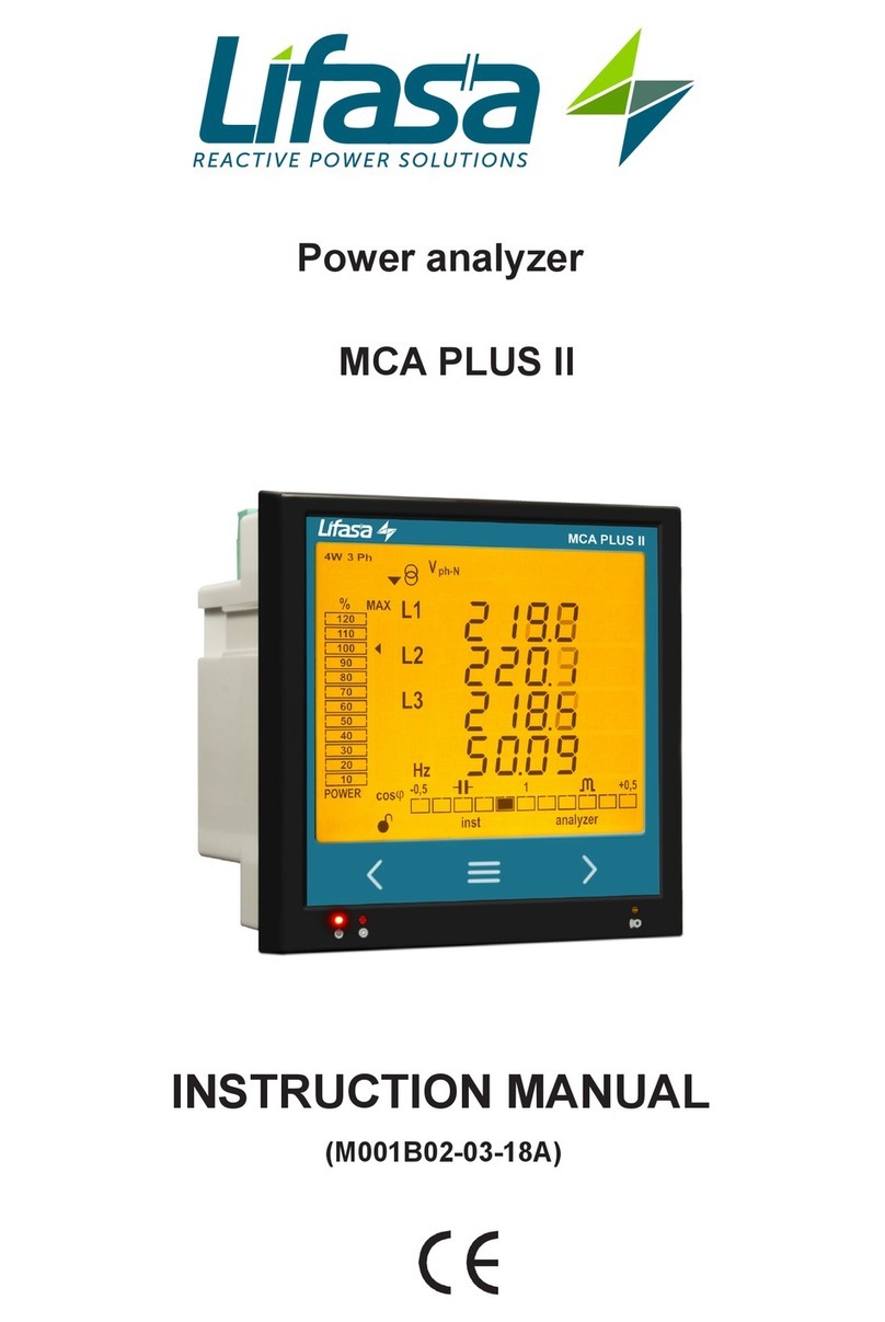
Lifasa MCA PLUS II User manual

INSTRUCTION MANUAL
Power analyzer
MCA PLUS II - ITF

2
MCA PLUS II - ITF
Instruction Manual

SAFETY PRECAUTIONS
DISCLAIMER
LIFASA reserves the right to make modifi cations to the device or the unit specifi cations set
out in this instruction manual without prior notice.
LIFASA on its web site, supplies its customers with the latest versions of the device specifi ca-
tions and the most updated manuals.
www.lifasa.com
DANGER
Warns of a risk, which could result in personal injury or material damage.
ATTENTION
Indicates that special attention should be paid to a specifi c point.
Follow the warnings described in this manual with the symbols shown below.
If you must handle the unit for its installation, start-up or maintenance, the following
should be taken into consideration:
Incorrect handling or installation of the unit may result in injury to personnel as well as damage
to the unit. In particular, handling with voltages applied may result in electric shock, which may
cause death or serious injury to personnel. Defective installation or maintenance may also
lead to the risk of fi re.
Read the manual carefully prior to connecting the unit. Follow all installation and maintenance
instructions throughout the unit’s working life. Pay special attention to the installation stan-
dards of the National Electrical Code.
Refer to the instruction manual before using the unit
In this manual, if the instructions marked with this symbol are not respected or carried out correctly, it can
result in injury or damage to the unit and /or installations.
LIFASA reserves the right to modify features or the product manual without prior notifi cation.
3
Instruction Manual
MCA PLUS II - ITF

CONTENTS
SAFETY PRECAUTIONS ���������������������������������������������������������������������������������������������������������������������������������������3
DISCLAIMER ����������������������������������������������������������������������������������������������������������������������������������������������������������3
CONTENTS�������������������������������������������������������������������������������������������������������������������������������������������������������������4
REVISION LOG�������������������������������������������������������������������������������������������������������������������������������������������������������6
1�- VERIFICATION UPON RECEPTION�����������������������������������������������������������������������������������������������������������������7
2�- PRODUCT DESCRIPTION��������������������������������������������������������������������������������������������������������������������������������7
3�- UNIT INSTALLATION ����������������������������������������������������������������������������������������������������������������������������������������8
3�1�- PRIOR RECOMMENDATIONS�������������������������������������������������������������������������������������������������������������������8
3�2�- INSTALLATION ������������������������������������������������������������������������������������������������������������������������������������������9
3�3�- UNIT TERMINALS������������������������������������������������������������������������������������������������������������������������������������10
3�3�1�- List of terminals, MCA PLUS II model������������������������������������������������������������������������������������������ 10
3�4�- CONNECTION DIAGRAM������������������������������������������������������������������������������������������������������������������������ 11
3�4�1�- Measuring Three-Phase Networks with a 4-wire connection, MCA PLUS II model� ���������������� 11
3�4�2�- Measuring Three-Phase Networks with a 3-wire connection, MCA PLUS II model ���������������� 12
3�4�3�- Measuring Three-Phase Networks with a 3-wire connection and transformers with an
ARON connection, MCA PLUS II model ��������������������������������������������������������������������������������������13
3�4�4�- Measuring Two-Phase Networks with a 3-wire connection, MCA PLUS II model� ������������������� 14
3�4�5�- Measuring Single-Phase Networks, phase to phase, with a 2-wire connection,
MCA PLUS II model ������������������������������������������������������������������������������������������������������������������������15
3�4�6�- Measuring Single-Phase Networks, phase to neutral, with a 2-wire connection,
MCA PLUS II model ������������������������������������������������������������������������������������������������������������������������16
4�- OPERATION ����������������������������������������������������������������������������������������������������������������������������������������������������17
4�1�- MEASURING PARAMETERS ������������������������������������������������������������������������������������������������������������������ 17
4�2�- KEYBOARD FUNCTIONS������������������������������������������������������������������������������������������������������������������������18
4�3�- DISPLAY ���������������������������������������������������������������������������������������������������������������������������������������������������20
4.3.1. COS φ - PF (POWER FACTOR) BAR����������������������������������������������������������������������������������������������20
4�3�2� ANALOGUE BAR �����������������������������������������������������������������������������������������������������������������������������21
4�3�3� OTHER SYMBOLS ON THE DISPLAY��������������������������������������������������������������������������������������������22
4�4�- LED INDICATORS������������������������������������������������������������������������������������������������������������������������������������22
4�5�- OPERATION PROFILES ��������������������������������������������������������������������������������������������������������������������������22
4�5�1� ANALYZER PROFILE����������������������������������������������������������������������������������������������������������������������� 22
4�5�2� e3PROFILE���������������������������������������������������������������������������������������������������������������������������������������29
4�5�3� USER ������������������������������������������������������������������������������������������������������������������������������������������������ 29
4�6�- HARMONICS ��������������������������������������������������������������������������������������������������������������������������������������������29
4�7�- INPUTS �����������������������������������������������������������������������������������������������������������������������������������������������������30
4�8�- OUTPUTS �������������������������������������������������������������������������������������������������������������������������������������������������30
4�9�- PROGRAMMING �������������������������������������������������������������������������������������������������������������������������������������� 31
4�9�1� Primary voltage ������������������������������������������������������������������������������������������������������������������������������� 32
4�9�2� Secondary voltage ��������������������������������������������������������������������������������������������������������������������������33
4�9�3� Primary current �������������������������������������������������������������������������������������������������������������������������������33
4�9�4� Secondary current ��������������������������������������������������������������������������������������������������������������������������34
4�9�5� Number of quadrants����������������������������������������������������������������������������������������������������������������������34
4�9�6� Type of installation��������������������������������������������������������������������������������������������������������������������������34
4�9�7� Maximum demand integration period �������������������������������������������������������������������������������������������35
4�9�8� Deleting maximum demand �����������������������������������������������������������������������������������������������������������36
4.9.9. Selecting the operation prole ������������������������������������������������������������������������������������������������������36
4�9�10� Backlight, Turning on the backlit display �����������������������������������������������������������������������������������37
4.9.11. Selecting the Cos φ - PF bar on the display �������������������������������������������������������������������������������38
4�9�12� Deleting maximum and minimum values������������������������������������������������������������������������������������38
4�9�13� Deleting energy values ����������������������������������������������������������������������������������������������������������������� 39
4�9�14� Selecting the Range of energies��������������������������������������������������������������������������������������������������39
4�9�15� Activating the harmonics display screen� ���������������������������������������������������������������������������������� 39
4�9�16� kgC02carbon emission ratio of generated energy �������������������������������������������������������������������40
4�9�17� kgC02carbon emission ratio of consumed energy�������������������������������������������������������������������41
4�9�18� Cost Ratio of generated energy�������������������������������������������������������������������������������������������������� 41
4�9�19� Cost Ratio of consumed energy ������������������������������������������������������������������������������������������������� 42
4.9.20. Programming alarm 1 (Relay 1) �������������������������������������������������������������������������������������������������� 42
4.9.21. Programming alarm 2 (Relay 2) �������������������������������������������������������������������������������������������������� 47
4.9.22. Programming alarm 3 (Digital output T1) ����������������������������������������������������������������������������������47
4
MCA PLUS II - ITF
Instruction Manual

4.9.23. Programming alarm 4 (Digital output T2) ����������������������������������������������������������������������������������49
4�9�24� Operating mode of digital input 1����������������������������������������������������������������������������������������������� 50
4�9�25� Operating mode of digital input 2����������������������������������������������������������������������������������������������� 50
4�9�26� Modbus Communications: Peripheral number �������������������������������������������������������������������������50
4�9�27� Modbus Communications: Transmission speed ����������������������������������������������������������������������51
4�9�28� Modbus Communications: Parity ����������������������������������������������������������������������������������������������� 51
4�9�29� Modbus Communications: Number of data bits �����������������������������������������������������������������������52
4�9�30� Modbus Communications: Number of Stop bits�����������������������������������������������������������������������52
4�9�31� Locking the programming����������������������������������������������������������������������������������������������������������� 52
4�9�32� Password �������������������������������������������������������������������������������������������������������������������������������������� 53
4�10�- COMMUNICATIONS�������������������������������������������������������������������������������������������������������������������������������54
4�10�1� CONNECTIONS����������������������������������������������������������������������������������������������������������������������������� 54
4�10�2� PROTOCOL ����������������������������������������������������������������������������������������������������������������������������������� 55
4�10�3� COMANDOS MODBUS����������������������������������������������������������������������������������������������������������������� 56
5�- TECHNICAL FEATURES ��������������������������������������������������������������������������������������������������������������������������������65
6�- MAINTENANCE AND TECHNICAL SERVICE������������������������������������������������������������������������������������������������68
7�- GUARANTEE���������������������������������������������������������������������������������������������������������������������������������������������������68
5
Instruction Manual
MCA PLUS II - ITF

REVISION LOG
Table 1: Revision log�
Date Revision Description
04/14 M001B01-03-14A Initial Version
06/14 M001B01-03-14B Changes in the following sections:
3.4 - 4.9 - 4.10 - 5
06/14 M001B01-03-14C Changes in the following sections:
4.9.5 - 4.9.6 - 4.10.2.1
11/14 M001B01-03-14D Changes in the following sections:
4.9.21 - 4.9.23 - 4.10.2 - 4.10.3 - 5
11/14 M001B01-03-14E Changes in the following sections:
3.3.2 - 3.4.2 - 3.4.8 - 4.5 - 4.9 - 4.10.3.1
6
MCA PLUS II - ITF
Instruction Manual

1�- VERIFICATION UPON RECEPTION
Check the following points when you receive the unit:
a)Theunitmeetsthespecicationsdescribedinyourorder.
b)Theunithasnotsufferedanydamageduringtransport.
c) Perform an external visual inspection of the unit prior to switching it on.
d)Checkthatithasbeendeliveredwiththefollowing:
-Aninstallationguide,
-2Retainersusedtoattachtheunit,
- 5 connectors.
Ifanyproblemisnoticeduponreception,immediatelycontactthetransport
companyand/orLIFASA's after-sales service.
2�- PRODUCT DESCRIPTION
The MCA PLUS II unitmeasures,calculatesanddisplaysthemainelectricalparametersofthe
followingnetworks:single-phase,two-phase,withandwithoutneutral,balancedthree-phase,
withARON measurements or unbalanced.The measurement will be taken in RMS with the
threeACvoltageinputsandthreecurrentinputs.
The unit features:
- 3 keysthatallowyoutobrowsebetweenthevariousscreensandprogramtheunit.
- 3 indicator LEDs:CPU,ALARMandKEY.
- LCD display,displaysallparameters,
- 2 digital inputs,usedtoselectthetariffordetectthelogicstateofexternalsignals.
- 2 digital outputs,fullyprogrammable.
- 2 alarm relays,fullyprogrammable.
- RS-485Communications,MODBUSRTU©.
7
Instruction Manual
MCA PLUS II - ITF

3�- UNIT INSTALLATION
3.1.-PRIORRECOMMENDATIONS
Inordertousetheunitsafely,itiscriticalthatindividualswhohandleitfollow
thesafetymeasuressetoutinthestandardsofthecountrywhereitisbeing
used,usethenecessarypersonalprotectiveequipment,andpayattentionto
thevariouswarningsindicatedinthisinstructionmanual.
The MCA PLUS IIunitmustbeinstalledbyauthorisedandqualiedstaff.
Thepowersupplyplugmustbedisconnectedandmeasuringsystemsswitchedoffbefore
handling,alteringtheconnectionsorreplacingtheunit.Itisdangeroustohandletheunit
whileitispowered.
Also,itiscriticaltokeepthecablesinperfectconditioninordertoavoidaccidents,personal
injuryanddamagetoinstallations.
Themanufactureroftheunitisnotresponsibleforanydamageresultingfromfailurebythe
userorinstallertoheedthewarningsand/orrecommendationssetoutinthismanual,norfor
damageresultingfromtheuseofnon-originalproductsoraccessoriesorthosemadebyother
manufacturers.
Ifananomalyormalfunctionisdetectedintheunit,donotuseittotakeanymeasurements.
Inspecttheworkareabeforetakinganymeasurements.Donottakemeasurementsindan-
gerous areas or where there is a risk of explosion.
Disconnecttheunitfromthepowersupply(unitandmeasuringsystempower
supply)beforemaintaining,repairingorhandlingtheunit'sconnections.
Please contact the after-sales service if you suspect that there is an operational
fault in the unit.
8
MCA PLUS II - ITF
Instruction Manual

3.2.-INSTALLATION
Theunitwillbeinstalledonapanel(92+0.8 x 92+0.8mmpaneldrillhole,incompliancewithDIN
43700).Allconnectionsarelocatedinsidetheelectricpanel.
Terminals,openingcoversorremovingelementscanexposepartsthatare
hazardoustothetouchwhiletheunitispowered.Donotusetheunituntilitis
fullyinstalled.
Theunitmustbeconnectedtoapowercircuitthatisprotectedwithgl(IEC269)orMtype
fuseswitharatingof0.5to2A.Itmustbettedwithacircuitbreakerorequivalentdevice,
inordertobeabletodisconnecttheunitfromthepowersupplynetwork.
Thepowerandvoltagemeasuringcircuitmustbeconnectedwithcablesthathaveamini-
mum cross-section of 1mm2.
Thesecondarylineofthecurrenttransformerwillhaveaminimumcross-sectionof2.5
mm2.
9
Instruction Manual
MCA PLUS II - ITF

3.3.-UNITTERMINALS
3�3�1�- List of terminals, MCA PLUS II model
Table 2:List of terminals of the MCA PLUS II
Unit terminals
1:A1 Auxiliary power supply. 13: I2,digitalinput2/tariffselection
2: A2 Auxiliary power supply. 14: VL1, Voltage input L1
3: Rc,Commonrelayoutput 15: VL2, VoltageinputL2
4: R2,Relayoutput2 16: VL3,Voltage input L3
5: R1,Relayoutput1 17: N, Neutral
6: CT,Commondigitaloutput. 18: S1 , CurrentinputL1
7: T2,Digitaloutput2 19: S2, CurrentinputL1
8: T1,Digitaloutput1 20: S1, CurrentinputL2
9: A(+),RS485 21: S2, CurrentinputL2
10: B(-),RS485 22: S1, CurrentinputL3
11: GND,forRS485anddigitalinputs
23: S2, CurrentinputL3
12: I1,digitalinput1/tariffselection
1
23 4 5 6 7 8910 11 12
13
14 15 16 17 18 19 20 21 22 23
POWER SUPPLY
INPUTS
A(+) B(-)
GND
RS485
S1 S2 S1 S2 S1 S2
L1
P1 P2
L2 L3
300V
~
Ph-NPh-Ph
520V ~
NV
L3L2
V
L1
V
P1 P2 P1 P2
I1 I2
OUTPUTS
Rc R2 R1 Tc T2 T1
S0-
S0+ S0+
Figure 1:Terminals of the MCA PLUS II
10
MCA PLUS II - ITF
Instruction Manual

3.4.- CONNECTION DIAGRAM
3�4�1�- Measuring Three-Phase Networks with a 4-wire connection, MCA PLUS II model�
Measurement system:
Power
Supply
VL1 VL2 VL3 N
L1
L2
L3
N
POWER SUPPLY
INPUTS
A(+) B(-)
GND
RS485
S1 S2 S1 S2 S1 S2
L1
P1 P2
L2 L3
300V
~
Ph-NPh-Ph
520V ~
NV
L3L2
V
L1
V
P1 P2 P1 P2
I1 I2
OUTPUTS
Rc R2 R1 Tc T2 T1
S0-
S0+ S0+
VL1 VL2 VL3
ab
A B
ab
A B
S1 S2
P1 P2 S1 S2
P1 P2 S1 S2
P1 P2
LOAD
Figure 2: Three-Phase measuring with a 4-wire connection, MCA PLUS II model�
11
Instruction Manual
MCA PLUS II - ITF

3�4�2�- Measuring Three-Phase Networks with a 3-wire connection, MCA PLUS II model�
Measurement system:
Power
Supply
VL1 VL2 VL3
L1
L2
L3
POWER SUPPLY
INPUTS
A(+) B(-)
GND
RS485
S1 S2 S1 S2 S1 S2
L1
P1 P2
L2 L3
300V
~
Ph-NPh-Ph
520V ~
NV
L3L2
V
L1
V
P1 P2 P1 P2
I1 I2
OUTPUTS
Rc R2 R1 Tc T2 T1
S0-
S0+ S0+
VL1 VL2 VL3
ab
AB
ab
A B
S1 S2
P1 P2 S1 S2
P1 P2 S1 S2
P1 P2
LOAD
Figure 3: Three-Phase measuring with a 3-wire connection, MCA PLUS II model�
12
MCA PLUS II - ITF
Instruction Manual

3�4�3�- Measuring Three-Phase Networks with a 3-wire connection and transformers
with an ARON connection, MCA PLUS II model�
Measurement system:
Power
Supply
VL1 VL2 VL3
L1
L2
L3
POWER SUPPLY
INPUTS
A(+) B(-)
GND
RS485
S1 S2 S1 S2 S1 S2
L1
P1 P2
L2 L3
300V
~
Ph-NPh-Ph
520V ~
NV
L3L2
V
L1
V
P1 P2 P1 P2
I1 I2
OUTPUTS
Rc R2 R1 Tc T2 T1
S0-
S0+ S0+
VL1 VL2 VL3
ab
A B
ab
A B
S1 S2
P1 P2
S1 S2
P1 P2
LOAD
Figure 4: Three-Phase measuring with a 3-wire connection and transformers
with an ARON connection, MCA PLUS II
MCA PLUS IImodel:
Thetransformersecondaryvaluemustbe5Aor1A
13
Instruction Manual
MCA PLUS II - ITF

3�4�4�- Measuring Two-Phase Networks with a 3-wire connection, MCA PLUS II�
Measurement system:
Power
Supply
VL1 VL2 N
L1
L2
N
POWER SUPPLY
INPUTS
A(+) B(-)
GND
RS485
S1 S2 S1 S2 S1 S2
L1
P1 P2
L2 L3
300V
~
Ph-NPh-Ph
520V ~
NV
L3L2
V
L1
V
P1 P2 P1 P2
I1 I2
OUTPUTS
Rc R2 R1 Tc T2 T1
S0-
S0+ S0+
VL1 NVL2
ab
AB
a b
A B
S1 S2
P1 P2 S1 S2
P1 P2
LOAD
Figure 5: Measuring Two-Phase Networks with a 3-wire connection, MCA PLUS II model
MCA PLUS IImodel:
Thetransformersecondaryvaluemustbe5Aor1A
14
MCA PLUS II - ITF
Instruction Manual

3�4�5�- Measuring Single-Phase Networks, phase to phase, with a 2-wire connection,
MCA PLUS II model�
Measurement system:
Power
Supply
VL1 VL2
L1
L2
POWER SUPPLY
INPUTS
A(+) B(-)
GND
RS485
S1 S2 S1 S2 S1 S2
L1
P1 P2
L2 L3
300V
~
Ph-NPh-Ph
520V ~
NV
L3L2
V
L1
V
P1 P2 P1 P2
I1 I2
OUTPUTS
Rc R2 R1 Tc T2 T1
S0-
S0+ S0+
VL1 VL2
a b
A B
S1 S2
P1 P2
LOAD
Figure 6: Measuring Single-Phase Networks, phase to phase, with a 2-wire connection, MCA PLUS II model�
MCA PLUS IImodel:
Thetransformersecondaryvaluemustbe5Aor1A
15
Instruction Manual
MCA PLUS II - ITF

3�4�6�- Measuring Single-Phase Networks, phase to neutral, with a 2-wire connection,
MCA PLUS II model�
Measurement system:
Power
Supply
VL1 N
L1
N
POWER SUPPLY
INPUTS
A(+) B(-)
GND
RS485
S1 S2 S1 S2 S1 S2
L1
P1 P2
L2 L3
300V
~
Ph-NPh-Ph
520V ~
NV
L3L2
V
L1
V
P1 P2 P1 P2
I1 I2
OUTPUTS
Rc R2 R1 Tc T2 T1
S0-
S0+ S0+
VL1 N
a b
A B
S1 S2
P1 P2 LOAD
Figure 7: Measuring Single-Phase Networks, phase to neutral, with a 2-wire connection, MCA PLUS II
MCA PLUS IImodel:
Thetransformersecondaryvaluemustbe5Aor1A
16
MCA PLUS II - ITF
Instruction Manual

4�- OPERATION
The MCA PLUS IIisafour-quadrantpoweranalyzer(consumptionandgeneration).
0º
90º
180º
-90º
Capacitive
Capacitive Inductive
Inductive
Generation
Power
Consumption
Power
Single-phaseThree-phase
Single-phase
Single-phase
Single-phase Three-phase Three-phase
Three-phase
k
k
k
k
k
k
k
k
k
k
k
k
k
k
kk
k
k
k
k
Figure 8: Four quadrants of MCA PLUS II
4.1.-MEASURINGPARAMETERS
TheunitdisplaystheelectricalparametersshowninTable 4.
Table 3: Measuring parameters of the MCA PLUS II�
Parameter Units Phases
L1-L2-L3
Total
III
N
Phase-neutral voltage Vph-N
Phase-phase voltage Vph-ph
Current A
Frequency Hz
Active power M/kW
Apparent power M/kVA
Total Reactive Power M/kvar
Total Reactive Power - Consumption M/kvar
Total Reactive Power - Generation M/kvar
TotalInductiveReactivePower M/kvarL
InductiveReactivePower-Consumption M/kvarL
InductiveReactivePower-Generation M/kvarL
Total Capacitive Reactive Power M/kvarC
Capacitive Reactive Power - Consumption M/kvarC
Capacitive Reactive Power - Generation M/kvarC
Power factor PF
Cosφ φ
THD % Voltage % THD V
THD % Current % THD A
HarmonicBreakdown-Voltage
(uptothe31storderharmonic)
harm V
17
Instruction Manual
MCA PLUS II - ITF

Parameter Units Phases
L1-L2-L3
Total
III
N
HarmonicBreakdown-Current
(uptothe31storderharmonic)
harm V
Total Active Energy M/kWh
TotalInductiveReactiveEnergy M/kvarLh
Capacitive Reactive Energy M/kvarCh
Total Reactive Energy M/kvarh
Total Apparent Energy M/kVAh
Active Energy Tariff 1 M/kWh
InductiveReactiveEnergyTariff1 M/kvarLh
Active Energy Tariff 2 M/kWh
InductiveReactiveEnergyTariff2 M/kvarLh
Active Energy Tariff 3 M/kWh
InductiveReactiveEnergyTariff3 M/kvarLh
MaximumCurrentDemand A
MaximumDemandofActivepower M/kW
MaximumDemandofApparentPower M/kVA
Parameter Units Tariff: T1-T2-T3 Total
No. of hours hours
Cost COST
CO2Emissions kgCO2
4.2.-KEYBOARDFUNCTIONS
The MCA PLUS IIhas3keysthatallowyoutobrowsebetweenthevariousscreensandpro-
gram the unit.
Keyfunctionsonmeasuringscreens(Table 5):
Table 4: Key functions on measuring screens�
Key Short keystroke Long keystroke
(2 s)
Previous screen Display of minimum value
Next screen Display of maximum value
Browsingthedifferentproles
(analyzer,user,e3) Accessing the programming menu
DisplayoftheMaximumDemand
Active alarm information
Unlocks the active alarm
18
MCA PLUS II - ITF
Instruction Manual

Keyfunctionsonharmonicsscreens(Table 6):
Table 5: Key functions on harmonics screens�
Key Short keystroke Long keystroke
(2 s)
Output of the harmonics screens
Next screen
Browsingthedifferenttypesofhar-
monics
Accessing the programming
menu
Keyfunctionsontheprogrammingmenu,querymode(Table 7):
Table 6: Key functions on the programming menu, query mode�
Key Short keystroke Long keystroke
(2 s)
Previous screen Programming output
Next screen Programming output
Openingtheprogrammingmenuintheedit
mode
Keyfunctionsontheprogrammingmenu,editmode(Table 8):
Table 7: Key functions on the programming menu, edit mode�
Key Keystroke
Next page
Increasesthedigits(0-9)orrotatesbetweenthedifferentoptions.
Movesaneditabledigit(ashing)
19
Instruction Manual
MCA PLUS II - ITF

4.3.-DISPLAY
TheunithasabacklitLCDdisplayshowingalltheparameterslistedinTable 3.
Thedisplayisdividedintofourareas(Figure 14):
Figure 9: MCA PLUS II Display areas
The area with data per phasedisplaystheinstantaneous,maximumandminimum
valuesofeachphasebeingmeasuredorcalculatedbytheunit.
The total dataareadisplaysthetotalsofthevaluesbeingmeasuredorcalculatedby
the unit.
Analogue bar,displaysthe%ofthecurrentpoweroftheinstallation.
Cos φ - PF Bar,displaysthevalueofthesystem'sCosφor power factor in real time.
4�3�1� COS φ - PF (POWER FACTOR) BAR
Figure 10: Cos φ - PF Bar
Thisbardisplaysthevalueoftheinstallation'scosφor power factor in real time.
Theparameterthatwillbedisplayedisselectedontheprogrammingmenu.(“4.9.11. Select-
ing the Cos φ - PF bar on the display”)
20
MCA PLUS II - ITF
Instruction Manual
Other manuals for MCA PLUS II
1
Table of contents
Other Lifasa Measuring Instrument manuals