Lifetech Solutions XT-3 User manual

Owner’s Manual
XT-3

Owner’s Manual
ess xt-3
LIFETECH SOLUTIONS, INC
19051 Goldenwest Street, Suite. 106.
Box #133 Huntington Beach, CA 92648
Phone: 714-369-8971 Fax: 714-657-3644
CE certication applied for
Copyright © 2009, – All Rights Reserved
This manual last updated January 13, 2010

i
XT-3 OWNER’S MANUAL
COnGratulatIOns!
You have just purchased one of the most advanced spraying systems
on the market today. Electrostatic Spraying Systems, Inc.1(ESS) is
committed to providing you with powerful spraying systems that are
easy to operate and maintain.
The products of ESS are the result of the efforts and creativity of many
people. In addition to input from engineering, marketing and manufac-
turing personnel, suggestions from our customers have been imple-
mented into the design of our equipment.We would like to hear your
ideas also! If you have any suggestions or comments regarding the
products or service of ESS write or call us at:
LIFETECH SOLUTIONS, INC
19051 Goldenwest Street, Suite. 106.
Box #133 Huntington Beach, CA 92648
Phone: 714-369-8971
Fax: 714-657-3644
Please take time to read this manual before operating your new ESS
XT-3 Sprayer™.The manual contains important instructions for the
safe operation of this equipment. It also includes helpful suggestions
to maximize productive use of the XT-3. Essential cleaning instructions
should be followed to maintain your sprayer at peak efficiency. Please
carefully read and follow all instructions for your own safety and the
safety of others around you.
Thank you!
We appreciate your business and are proud that you have selected an
ESS sprayer for your operation.
Your new sprayer has been thoroughly tested and calibrated at the
factory. If you have any problems with it, please get in touch with us
immediately.We will be glad to answer any questions you have con-
cerning our equipment or service. ESS intends to support its customers
with efficient, helpful and friendly service.We appreciate your business.
.
1 ESS XT-3 Sprayer ™, XT™, MaxCharge™, and the ESS logo are copyrights or registered trademarks
of Electrostatic Spraying Systems, Inc.
For your personal records
Please record the model
and serial numbers of your
new sprayer here.
XT-3
______________________
Model #
______________________
Serial #
______________________
Spray gun serial number
______________________
Date of purchase.

ii
XT-3 OWNER’S MANUAL
Notes

iii
XT-3 OWNER’S MANUAL
table Of COntents
Overview of ESS XT-3 Air-Assisted Electrostatic Sprayer..............................1
Operator’s Responsibility ........................................................................................2
CAUTION: Shock hazard...........................................................................................2
Chemical Safety Precautions..................................................................................3
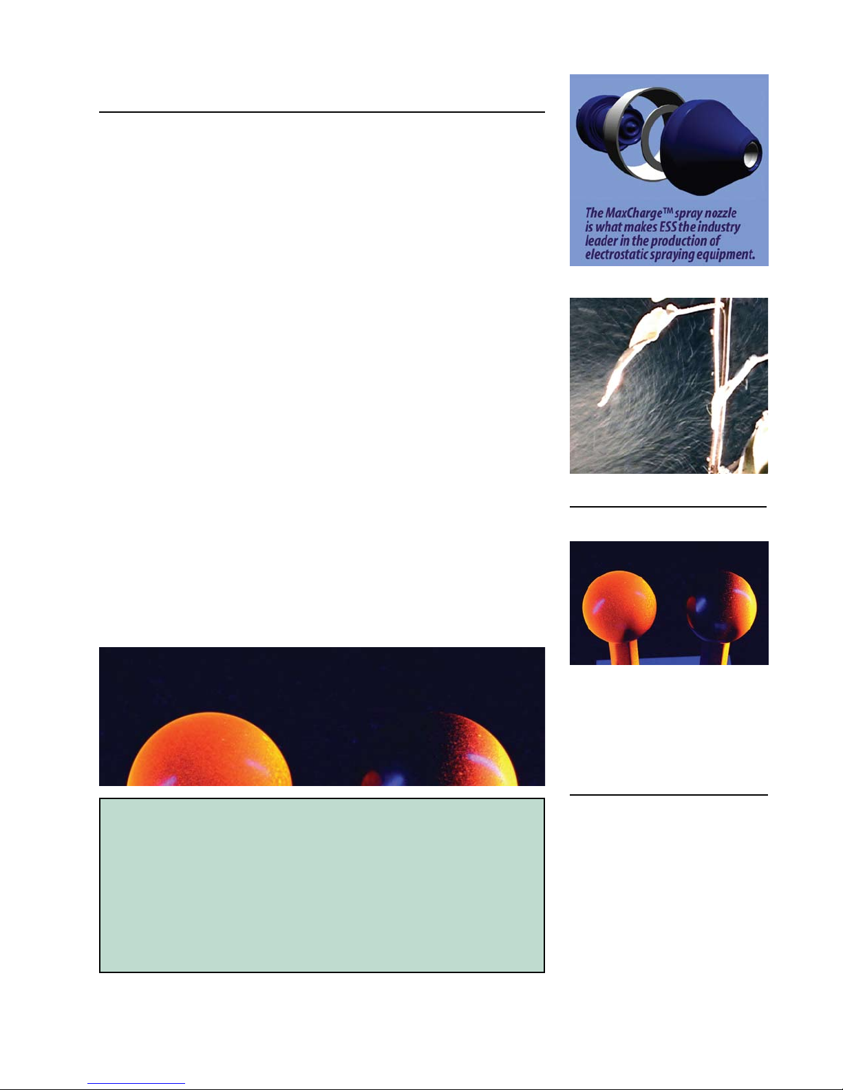
About the low-voltage system of the MaxCharge Spray gun....................3
Safety Decals ...................................................................................................4
Front and Side view of the XT-3™ .........................................................................5
Operating Instructions .............................................................................................6
Steps for Operation................................................................................................6
To clean the XT-3 after operation .....................................................................7
REFERENCE
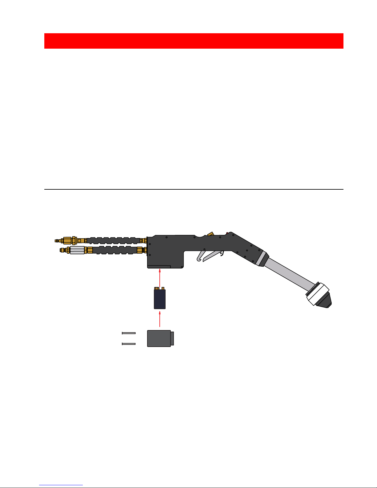
Spray gun ...................................................................................................8
Air Filter ...................................................................................................9
To clean the air lter..........................................................................................9
Trigger ................................................................................................ 10
To engage/disengage the trigger ............................................................. 10
To clean the trigger......................................................................................... 10
Liquid Filter Assembly ...................................................................................... 11
To disassemble, clean, and reassemble the
liquid lter assembly .............................................................................. 11
Nozzle Assembly ................................................................................................ 12
To clean nozzle assembly ..................................................................... 12
Pre-spray check ................................................................................................ 13
Post-spray check ................................................................................................ 13
The Air & Liquid Delivery System................................................................... 14
Air Compressor ................................................................................................ 14
Tank Pressure Regulator................................................................................ 14
The Quick Connects............................................................................................ 15
Air connection ................................................................................................ 15
Liquid connection ........................................................................................... 15
Tank ................................................................................................ 16
To open/close the tank.................................................................................. 16
Batteries ................................................................................................ 17
To change the batteries................................................................................. 17
Yearly Spraygun Service.................................................................................... 18
Spraying with Your ESS Sprayer...................................................................... 19
Spray Technique....................................................................................... 19
Preparing a Tank Mix .......................................................................................... 20
A note about operating temperatures ........................................................ 20
Trouble-Shooting Guide ....................................................................................... 21
Spray gun Service Parts......................................................................................... 22
Parts List ................................................................................................ 23
Flow disk chart ................................................................................................ 23
XT-3 Service Parts ........................ ..............................................................24 – 25
Warranty ................................................................................................ 27
Warranty Card ..............................................................................................27a
Spraygun Repair/Yearly Service Return Form............................................... 29

iv
XT-3 OWNER’S MANUAL
Notes

1
XT-3 OWNER’S MANUAL
Overview of the ESS Model XT-3 Air-Assisted
Electrostatic Sprayer
Air-assisted electrostatic sprayers produce electrically charged spray
drops that are carried to the plant canopy or onto the target in a low
pressure, gentle, air stream. The heart of the XT-3 Sprayer is the pat-
ented MaxCharge™ nozzle.
Air and liquid enter separately at the rear of the nozzle. Just before
leaving the nozzle, the air hits the liquid stream to make many thou-
sands of tiny spray droplets that pass through the charging ring. An
electrical charge is applied to the spray droplets by the charging ring.
Then the charged spray droplets are blown out of the nozzle and
move into the plant canopy where they are attracted to plant material
by electrostatic forces. The electrostatic charge induced by the Max-
Charge™ nozzle is strong enough to allow the droplets to move in any
direction to cover all plant surfaces, even defying gravity to coat the
underside of leaves and the back side of fruits, vegetables, and objects.
The result is uniform spray coverage on hidden surfaces that other
sprayers miss. Air-assisted electrostatic sprayers give more than twice
the deposition eciency of hydraulic sprayers and non-electrostatic
types of air-assisted sprayers. The grower benets in terms of signi-
cant reductions in application costs and optimized insect and disease
control, sanitization of beef or other coverage.
The MaxCharge™ nozzle is easy to clean and corrosion-proof. The inte-
rior ceramic outlet resists wear three times better than stainless steel
outlets. These features combine to give the best spray coverage on the
market. This quality product is virtually maintenance-free, and assures
you of savings in the application of chemical.
The comparison of air-assisted electrostatic spraying versus conven-
tional spraying is dramatic.
Electrostatically charged droplets are
attracted to plant surfaces.
Where Does the Spray Go?
The University of California completed a series of tests to investi-
gate what happens to spray liquid after it leaves the nozzle.
Conclusion: ESS technology places over 4 times the amount of
spray onto the plant surface using ½ the amount of chemicals.
Furthermore, they also reported that ESS sprayers send ⁄ less
chemicals to the ground and into the air. Less chemical used
overall, less waste and less drift than conventional equipment.
Imagine the environmental benet!
A picture worth a thousand words…
In this test, uorescent dye has been
sprayed on two round knobs. The left
knob was sprayed with the electrostatic
system ON; the right knob was sprayed
with the same sprayer, but with the elec-
trostatic system OFF. Note how even the
coverage is on the electrostatic knob.

2
XT-3 OWNER’S MANUAL
OPERATOR’S RESPONSIBILITY
Read the Owner’s Manual.
It is the responsibility of the user to read the Owner’s Manual, to understand the
safe and correct operating procedures which pertain to the operation of the prod-
uct, and to maintain the product according to the Owner’s Manual. It is the owner’s
responsibility to ensure that all who are using this equipment read this manual.
The user is responsible for inspecting the equipment and for repairing and replacing
damaged or worn parts to prevent damage or excessive wear to other parts. It is the
user’s responsibility to deliver the machine for service or replacement of defective
parts which are covered by the standard warranty.
Lack of attention to safety can result in reduction of eciency, accident, personal injury, or
death. Watch for safety hazards and correct deciencies promptly. Use the following safety
precautions as a guide when using this machine.
Use a GFCI (Ground Fault Circuit Interrupter) power outlet whenever possible.
If an extension cord is necessary, use a three-wire extension cord with a 3-prong grounding type plug.
Turn o sprayer before unplugging.
Unplug sprayer when not in use.
Always unplug by grasping the plug. Do not unplug by pulling on the cord.
Never pull plug with wet hands.
Do not pull or carry the sprayer by its power cord. Do not crimp the cord or cause it to be damaged by
straining it around sharp edges. Keep power cord away from heat sources.
Do not use the XT-3 sprayer with a damaged power cord. Call ESS for a replacement.
CautIOn: sHOCK HaZarD
Read the Owner's Manual. Failure to read the manual is considered a misuse of the equipment.
Use the XT-3 sprayer ONLY for its intended use as described in this manual.
Use the XT-3 sprayer indoors only.
Do not allow a child to operate the XT-3 sprayer. Do not allow adults to operate the sprayer without
proper instruction.
Use extra care when spraying on stairs. Do not place sprayer on stairs.
Do not use without tank in place.
Always empty tank after use and before transporting the sprayer.
Store sprayer in a dry place. Do not expose to freezing temperatures.
The XT-3 sprayer has been engineered to be very safe during normal operation. However, as
with all line-powered electrical equipment and tools, certain safety procedures need to be
followed.

3
XT-3 OWNER’S MANUAL
CHeMICal safetY PreCautIOns
Read and follow all instructions on the chemical or pesticide manufacturer’s label.
Use protective clothing, eye protection and gloves when mixing chemicals to be sprayed with the
XT-3 sprayer.
Always use a respirator and eye protection when spraying with the XT-3.
Follow the chemical manufacturer’s recommendations in handling, mixing, applying, storing and
disposing of chemicals.
Be aware of decontamination methods in case a person, clothing, or equipment is accidentally
sprayed.
Be aware of poisoning symptoms and know the appropriate rst aid.
Know the length of time needed to pass before allowing people and pets to go back into the
sprayed area.
About the low-voltage system of the MaxCharge Spray gun
For operator safety, the power supply for the MaxCharge spray gun is entirely separate from the power
supply for the sprayer’s compressor. The .spray gun is powered by 9-volt batteries in the handle of the XT-3
sprayer. This low-voltage charge is not enough to harm people. Some people report feeling a “tingle” or a
slight stinging sensation when the spray from the spray gun falls on their bare skin.
9v

4
XT-3 OWNER’S MANUAL
Safety Decals
ESS places several decals1on the ESS XT-3 sprayer to remind the
operators of safety and proper techniques. Always follow good, safe
practices when operating this machinery. Note the locations on the
equipment where these decals may be found. Replace them if they
become worn or damaged and can no longer be read.
1ESS is currently redesigning the warning labels for the sprayers.There may be minor changes in
the layout and/or wording of the warning decals on your sprayer.
This decal is on the back of the
3-gallon stainless steel tank.
Be aware that many chemicals
are harmful if they are not used
properly. Read all instructions
and warnings on the chemi-
cal label. Make sure that the
sprayer operator has the ap-
propriate clothing and respi-
ratory gear. Clear the area
before spraying and do not
allow people to return until it
is safe. Do not leave leftover
chemicals where children or
animals may nd them.
¡PRECAUCIÓN!
WARNING!
AGRICULTURAL CHEMICALS CAN BE
DANGEROUS. IMPROPER SELECTION
OR USE CAN SERIOUSLY INJURE
PERSONS, ANIMALS, PLANTS, SOIL OR
OTHER PROPERTY.
BE SAFE:
·SELECT THE RIGHT CHEMICAL
FOR THE JOB.
·HANDLE IT WITH CARE.
·FOLLOW THE INSTRUCTIONS
ON THE CHEMICAL
MANUFACTURER’S LABEL.
LOS PRODUCTOS QUÍMICOS AGRÍCOLAS
PUEDEN SER PELIGROSOS. LA SELECCIÓN O EL
USO INAPROPIADOS PUEDEN LESIONAR
SERIAMENTE A LAS PERSONAS, LOS ANIMALES,
LAS PLANTAS, LA TIERRA U OTRA PROPIEDAD.
TENGA CUIDADO:
·
SELECCIONE EL PRODUCTO QUÍMICO
CORRECTO PARA EL TRABAJO.
· MANÉJELO CON CUIDADO.
· SIGA LAS INSTRUCCIONES DE LA ETIQUETA
DEL FABRIC ANTE DEL PRODUCTO
QUÍMICO.
This decal is also on the back
of the 3-gallon stainless steel
tank. The contents of the XT’s
tank are under pressure. Please
take care when releasing pres-
sure and when removing the
tank lid.
CLEAN
FILTER
REGULARLY
This label is wrapped around the hose to
remind you to clean the lters regularly.
The number one cause of poor sprayer
performance is a clogged or dirty lter.

5
XT-3 OWNER’S MANUAL
Connects To
Spray Gun
Liquid Line
Leader
Plastic Bottles
Tank
Liquid
Outlet
Tank
Air
Inlet
Tank
Pressure
Regulator;
Set Between
12 And 15 Psi
Air Line
Female
Ball
Swivel
Liquid Line
Female
Ball Swivel
Air Compressor
On/o Switch Electrical Plug
Connects To
Spray Gun
Air Line
Leader
Connects To
Air Line
Female Ball
Swivel
(Red Hose)
Connects To
Liquid Line
Female Ball
Swivel
(Grey Hose)
Adjustable
Air Compressor
Check Relief
Valve; Set
Between 70
And 100 Psi
Liquid Flow Regulator
Air Filter
Tank
Pressure
Gauge
Spray Gun
Liquid Line
Leader
Spray Gun
Air Line
Leader
Front and side view of the ESS XT-3™

6
XT-3 OWNER’S MANUAL
Operating Instructions
Steps for Operation
1. Prepare the tank mix.
2. Connect the twin line hose to the front panel.
3. Connect the twin line hose to the liquid and air leaders on
the handgun.
If using the plastic bottle, connect the gray
hose of the plastic bottle hose assembly instead of the
gray hose of the twin line hose to the liquid leader.
4. Plug the power cord into an appropriate receptacle.
Turn on the XT-3 air compressor.
5. Engage the trigger and spray.
Cautions:
ESS recommends that
you use an outlet with a
Ground-Fault Circuit
Interrupter (GFCI).
Do not operate the XT-3 in
standing water.
Do not immerse the XT-3
compressor.
!
SAFETY
FIRST!
Observe all
label warnings
when handling
chemicals.
Always use
Personal
Protective
Equipment
(PPE) when
spraying.

7
XT-3 OWNER’S MANUAL
To clean the XT-3 after operation:
1. Clean the exterior of the sprayer.
2. Clean the tank and/or the plastic bottles.
3. Disconnect the twin line hose from the handgun air line
and liquid line leaders.
4. Disassemble and clean the liquid lter. Be careful not to
lose the ow disk.
5. Unthread the quick connect plug from the handgun liquid
line leader. Use a ⁄” wrench on the plug and an
⁄” wrench on the ⁄”NPT body.
6. Connect the quick connect plug to the grey hose of the
twin line hose.
7. Fill the tank with 2 gallons of clean water.
8. Turn on the air compressor to ush the line with
1.75 gallons of water. Turn o the air compressor.
9. Disconnect the quick connect plug from the twin line hose.
Re-thread it into the handgun liquid line leader.
10. Reassemble the liquid lter.
11. Turn on the air compressor and engage the trigger to ush
the handgun lines with the remaining water. Check the
nozzles for a good spray pattern while ushing. Allow air to
ow for 30 seconds after the water has been sprayed.
12. Apply silicone spray or similar lubricating oil to all quick
connect ttings.
Sil-Glyde is an excellent silicone-based
protective lubricant. You may purchase
it directly from ESS.
Detailed cleaning
instructions for each
component are found in
the reference section of
this manual.

8
XT-3 OWNER’S MANUAL
referenCe
Spray gun
The spray gun is held by the operator during spraying. Activation
of the trigger causes liquid to spray. The Spray gun has the follow-
ing user-serviceable parts: the air lter, the liquid lter assembly, the
nozzle assembly, and the batteries. Except for the batteries, which are
accessed by removing the battery cover, nothing inside the Spray gun
shell is user-serviceable. Do not open the spray gun shell; doing so
will void the warranty on the spray gun.
NOTE
The Spray Gun
See also: Changing the batteries
Yearly Spray gun Service
Spray technique
Liquid Filter
Air Filter
Battery
Housing
Trigger
Lock
Brass Bolt
Trigger
Charging Indicator
Nozzle

9
XT-3 OWNER’S MANUAL
Air filter
Note: XT-3 units manufactured after March 2009 do not require an
air lter on the spray gun air leader.
For XT-3 units manufactured before March 2009, there is an in-line air
lter located outside the base of the spray gun in the air hose. It lters
dirt out of the air lines. It’s easy to tell the Air Filter from the Liquid
Filter Assembly because the Air Filter is in a silver-colored casing.
Replacement parts for the air lter assembly are available as a kit.
The kit includes a lter, and large and small o-rings.
Order using ESS part number 231.
To clean the air lter:
1. Unthread the casing from the cap using a ¾”wrench on
both parts. Be careful not to lose the spring or the air lter
inside of the casing.
2. Check inside each part for debris. Clean any dirt out with
compressed air or warm, soapy water.
3. Reassemble the air lter, making sure to put it together as
shown above.
Casing
Filter Element
Cap O-Ring
Cap
Filter O-Ring
Spring
The Air lter assembly

10
XT-3 OWNER’S MANUAL
Trigger
The trigger turns the spray on and o. It can be continuously held for
operation or it can be locked in place.
Brass Bolt
Pull Trigger Lock
forward to engage
Depress Trigger
to spray
To engage/disengage the trigger:
1. Depress the trigger up towards the body of the spray gun
to start spraying.
2. To keep spraying, either keep holding the trigger or lock it
in place by pulling up the lock and hooking the trigger.
3. To stop spraying when the trigger is not locked, let go of
the trigger.
To clean the trigger:
1. Unthread the brass bolt on the top of the spray gun with a
⁄” socket wrench. Be careful not to lose the spring, plunger,
copper washer, and small brass bushing inside the trigger.
Note how they t inside so they may be replaced properly.
2. Check inside the trigger for blockage. Clean out any debris
with compressed air or warm, soapy water.
3. Replace the spring and plunger; rethread the brass bolt into
the top of the spray gun until tight.

11
XT-3 OWNER’S MANUAL
Liquid filter assembly
The liquid lter assembly is located outside the base of the spray gun.
It is composed of these parts: a ⁄” NPT body (Item 12), a strainer
(Item 11), a ow disk (Item 10), an adapter (Item 9) and a cap (Item 8).
The strainer is the active ltering element in the volume of liquid that
ows through the line. There is an extra ow disk and an extra strainer
in the XT-3 Parts Kit in case the originals are lost or damaged.
To disassemble, clean and reassemble the liquid
lter (see labeled drawing above):
1. Using a ⁄” wrench on the cap (Item 8) and an ⁄” wrench
on the ⁄” NPT body (Item 12), unthread them.
Note: When you disassemble the liquid lter assembly, notice
how the parts t together in order to reassemble them
properly. Be careful not to lose any parts, particularly the
ow disk (Item 10) which is inside the cap. The sprayer will not
function correctly without the ow disk.
2. Remove the strainer (Item 11) from the ⁄”NPT body.
3. If the ⁄” NPT body contains residue, clean it with
compressed air or clean water.
4. Clean the strainer with compressed air or clean water. If
residue still remains in the 50 mesh screen, disassemble the
strainer. Unscrew the top brass part from the bottom brass
part. The 50 mesh screen slides o the brass body and can
be cleaned with compressed air or clean water. If residue
still remains, soak the 50 mesh screen and screw the top
brass part back on the lower brass part.
5. If the ow disk is still in the cap, remove it. Check the
aperture of the ow disk for blockage. If there is any, clean
it with compressed air or water. Replace the ow disk so
that the numbers on the disk face the strainer.
6. Replace the strainer in the ⁄” NPT body.
7. Rethread the ⁄” NPT body and the cap.
Liquid Filter Assembly
⁄” NPT Body (Item 12)
Strainer (Item 11)
Flow Disk (Item 10)
Adapter (Item 9)
Cap (Item 8)
You may have to clean the
liquid lter more
frequently if the XT-3 is
being used to spray high-
particle density solutions.

12
XT-3 OWNER’S MANUAL
Nozzle assembly
It is very important to follow all the maintenance
and cleaning procedures to ensure that the electro-
static sprayer will function properly. Although the
MaxCharge™ nozzle will outperform all electrostatic
spray technology on the market, regular cleaning
will ensure peak operating performance.
The nozzle assembly is located at the end of the
spray gun wand. It is composed of a nozzle body,
internal o-ring, Teon ring, cover, external o-ring,
and a hood (see labeled drawing at right). To access
the nozzle components, just unscrew the nozzle
cover by hand.
Cleaning the spray gun
Always rinse the spray gun out with clean soapy
water after every day’s spraying. That is the most
important thing you can do to ensure trouble free
operation of your XT-3 sprayer. By cleaning after
each and every working day you will avoid the long-
term chemical buildup that eventually causes clogs,
poor spray patterns and shortens nozzle life.
Establish maintenance intervals to disassemble and
clean the nozzle. Your nozzle maintenance schedule
will vary depending on the types of chemicals used
and adherence to pre- and post-spray checks. In
general it is sucient to thoroughly clean nozzles
every 50 hours. If heavy loads of wettable powers
are used, the cleaning schedule should be sooner.
To clean the nozzle assembly
1. Slide the hood over the nozzle cover.
2. Unscrew the cover from the nozzle base and remove the Teon ring. Clean any debris from
around the nozzle tip.
Note: There is a small o-ring in the nozzle around the base of the tip – take care that it doesn’t fall
o. If it does, clean it and press back into place. Also, take care not to damage the nozzle tip when
the cover is removed.
3. Soak the ring, cover, and hood in a mild detergent solution. Use a small brush (soft or mild
bristle) to clean the inside of the cover and the hole through it. Also, be sure to clean the hood.
It is important to clean inside the hood and the two cavities. Rinse thoroughly.
4. Scrub the nozzle base with the detergent solution using a soft bristle brush. Clean the ceramic
outlet. Be sure to thoroughly clean the base cavity and take care not to damage the nozzle tip.
Rinse and make sure the small o-ring is in place.
5. Reassemble nozzle by placing the Teon ring on the base and screwing the cover on hand
tight. Next, slide the hood over the nozzle and seat it securely against the external o-ring.
Wipe clean the exterior of all hoses and ttings connected to the nozzle.
The electrode cover should be hand tight. Never use pliers or other tools to tighten it. The insulating
ring should be loose.

13
XT-3 OWNER’S MANUAL
You may wish to purchase Nutrasol Tank Cleaner from ESS (S/N# 1566),
which cuts hard water scale and chemical deposits from the electrode
and internal component of the spray gun. The regular use of Nutra-Sol
will keep your equipment operating at peak performance. The recom-
mended mixing ratio is 4 ounces in 12.5 gallons of water (113 grams in
47 liters of water).
Pre-Spray Check
I. Inspect Nozzles
Check nozzle cover to make sure it is on hand tight (do not
over tighten or use a wrench). Make sure the hood is seated
rmly to the nozzle base and against the external o-ring.
II. Preparing the Tank Mix
If you will be spraying wettable powders it is a good idea to
use a compatibility agent with the water and tank mix.
Compatibility agents are chemicals mixed with the water
that make mixing easier and keep heavy concentrations
uniformly in suspension. Some brand name additives are
COMPLIMENT™, UNITE®, and BALANCE™. Check with your
local chemical supplier for others that are available.
Post-Spray Check
After each spray it is essential that hoses and spray gun be
ushed with clean soapy water. This will help prevent
chemical build-up that can clog lines and nozzles. Also, it is
recommended that the nozzle exterior (black portion of
nozzle) and nozzle hoods be cleaned with soapy water at this
time.
ESS recommends the use of
NUTRA-SOL cleaner which
can be purchased from ESS.
Order S/N#1566.
Location of the XT-3 power switch.

14
XT-3 OWNER’S MANUAL
The air & liquid delivery system
Air compressor
The air compressor produces compressed air which atomizes and
propels the liquid. It plugs into a 110 volt electrical source. Use the
XT-3™ with a three-pronged extension cord of no more than 50 feet
and rated for no less than 15 amp service. The On/O switch is on the
side of the air compressor.
Tank pressure regulator
There is a pressure regulator to control air pressure to the tank. It corre-
sponds with the pressure gauge on the left side of the front panel. This
regulator is operated by pulling out the dial and turning it clockwise
to increase pressure or counter-clockwise to decrease pressure in the
tank. This regulator controls the air pressure going to the tank not to
the spraygun. Generally tank pressure should be 15 psi. There are two
purposes for the tank pressurization: rst, to push the liquid solution
from the tank to the spraygun, and second, to agitate the liquid in the
tank, so that the chemical stays in solution. Once the desired pressure
is achieved, push in the dial to lock it in place. Some chemicals have
a tendency to foam. If you see any foam coming out the pressure
release tank value, either reduce the tank air pressure or add an “anti-
foaming” agent to the solution. In some occasions, it may be necessary
to lower tank pressure to avoid foaming, to even as low as 5 psi. When
adjusting tank pressure, one should dial pressure up to desired setting,
rather than down. Two air lines run from the tank pressure regulator.
One line runs to the tank pressure gauge on the front panel. The other
runs to the inlet quick connect on the tank.
The XT-3 is also available with
a 220-volt compressor.
Table of contents