2(13)
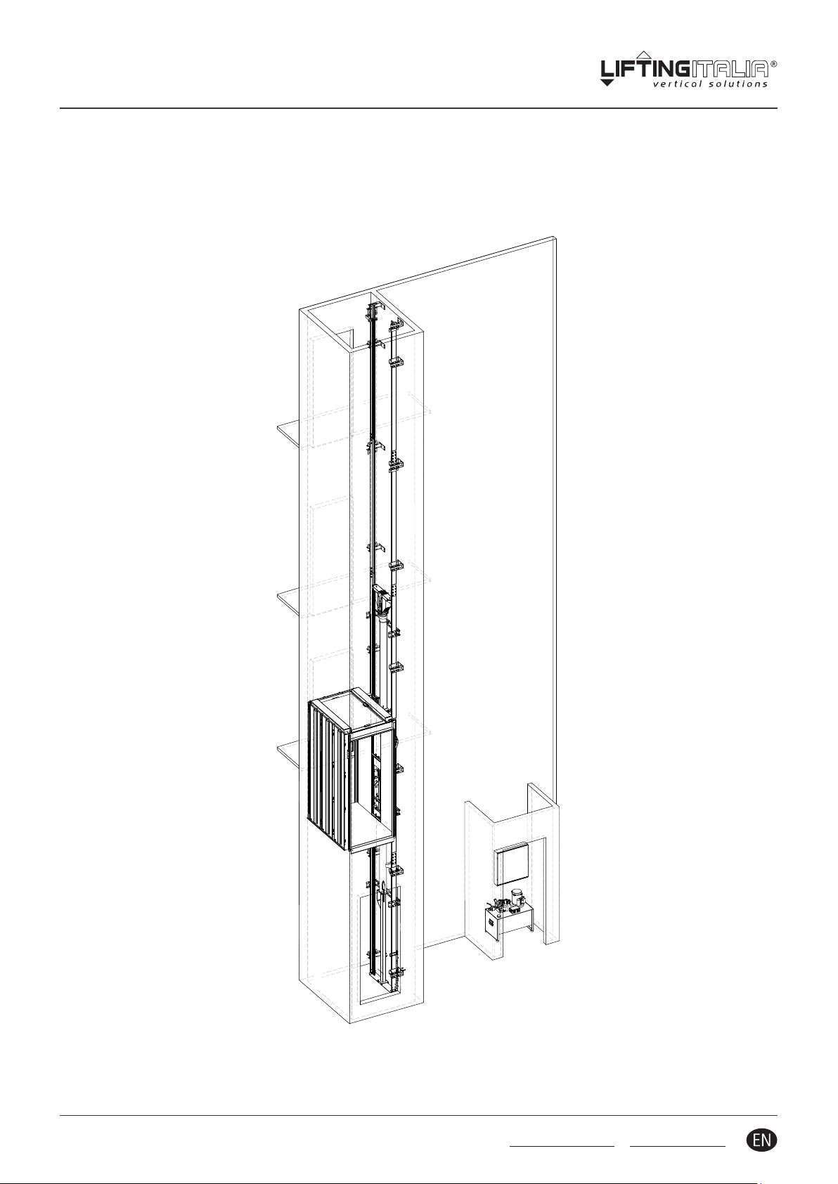
inDOMO HP - Plaorm li
FINAL TESTS
IM.TEC.028.EN_rev.10.2 - November 2015 All rights reserved
10.2 General update 30.11.2015
10.1 Update pages 5, 8 27.02.2014
10 General update and new layout 30.01.2013
Rev. Descrizione Data
INDEX
As far as the following items are concerned : general instrucons, safety instrucons,
responsibility and warranty, material receiving and storage on site, packing, waste disposal,
cleaning and maintenance, please consult the manual "SAFETY AND MATERIAL HANDLING
ON SITE".
0 MANUAL READING GUIDE ................................................................................................................ 3
0.1 CHAPTER SYMBOLS.......................................................................................................................3
0.2 IMPORTANT ITEMS .......................................................................................................................3
0.3 INDIVIDUAL SAFETY DEVICES...............................................................................................................3
1 COMMISSIONING AND HANDOVER........................................................................................................ 4
2 CONFORMITY TESTS ..................................................................................................................... 4
2.1 CONTROL PANEL TESTING .................................................................................................................5
2.2 FIRST TEST TRAVELS ......................................................................................................................5
2.3 SAFETY BRAKES TESTING ..................................................................................................................5
2.4 ORIGINAL MATERIALS FROM LIFTINGITALIA ..................................................................................................5
2.5 STRUCTURAL TEST........................................................................................................................5
2.6 MAXIMUM STATIC PRESSURE ..............................................................................................................5
2.7 HYDRAULIC CIRCUIT ......................................................................................................................5
2.8 BLOCK VALVE ............................................................................................................................5
2.9 OVERLOAD MANOSTAT ...................................................................................................................6
2.10 ASCENT AND DESCENT SPEED..............................................................................................................6
2.11 STOP PRECISION .........................................................................................................................6
2.12 SAFETY SPACE IN PIT ......................................................................................................................6
2.13 “STOP” (if present ) AND ALARM BUTTONS..................................................................................................7
2.14 EMERGENCY POWER SUPPLY ..............................................................................................................7
2.15 SHAFT CLOSURE..........................................................................................................................7
2.16 COMMANDS ............................................................................................................................7
2.17 CEILING CONTACT . . . . . . . . . . . . . . . . . . . . . . . . . . . . . . . . . . . . . . . . . . . . . . . . . . . . . . . . . . . . . . . . . . . . . . . . . . . . . . . . . . . . . . . . . . . . . . . . . . . . . . . . . . . . . . . . . . . . . . . . 7
2.18 COP CONTACT ...........................................................................................................................7
2.19 OVERRUN CONTACT AND HEADROOM SPACER ...............................................................................................8
2.20 LANDING DOOR LOCKS....................................................................................................................8
2.21 DISTANCES FROM THE ENTRANCE ..........................................................................................................8
2.22 CAR LEVELLING DISTANCE .................................................................................................................8
2.23 CAR LEVELLING ..........................................................................................................................8
2.24 MANUAL PUMP..........................................................................................................................9
2.25 OVERPRESSURE VALVE TEST ...............................................................................................................9
2.26 PULLEY SAFETY COVERS ...................................................................................................................9
2.27 GUIDE BRACKETS CENTER TO CENTER DISTANCE..............................................................................................9
2.28 GROUNDING CONNECTION................................................................................................................9
2.29 ELECTRICAL COMPONENTS INSULATION.....................................................................................................9
2.30 SHAFT LIGHTING AND SOCKET (if any).......................................................................................................9
2.31 PHOTOCELLS OR LIGHT BARRIERS (if any) ...................................................................................................10
2.32 BUTTON ENABLING KEY (oponal).........................................................................................................10
2.33 CONTROL CABINET ......................................................................................................................10
2.34 SIGNAGE ...............................................................................................................................10
2.35 NOISE EMISSION ........................................................................................................................10