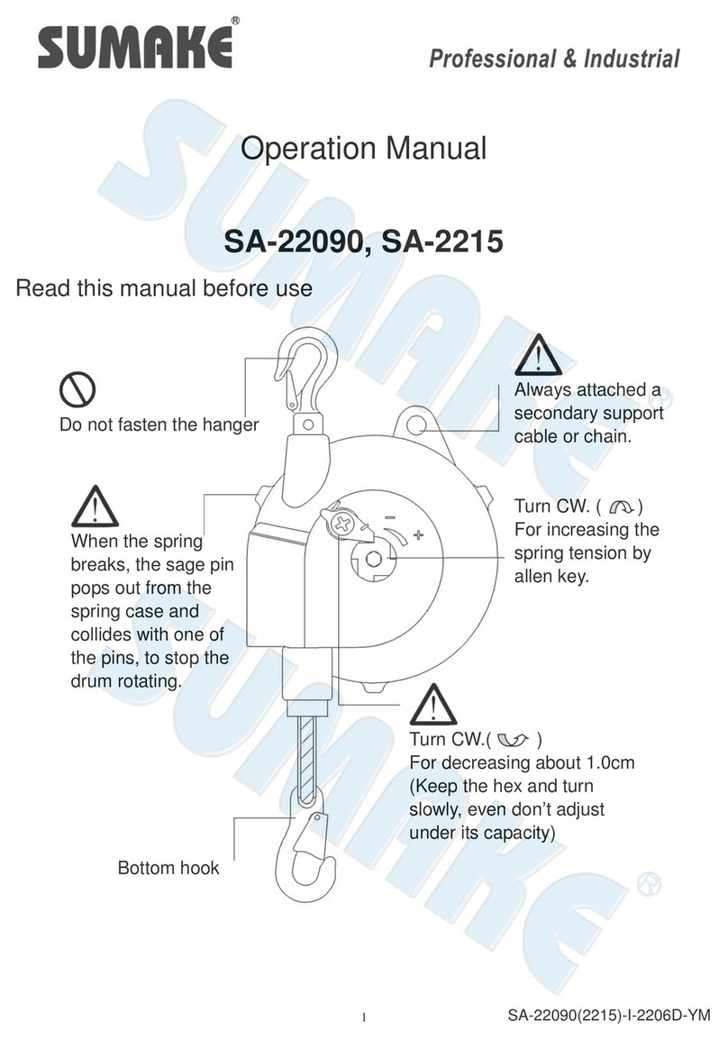
Sumake SA-22900 User manual

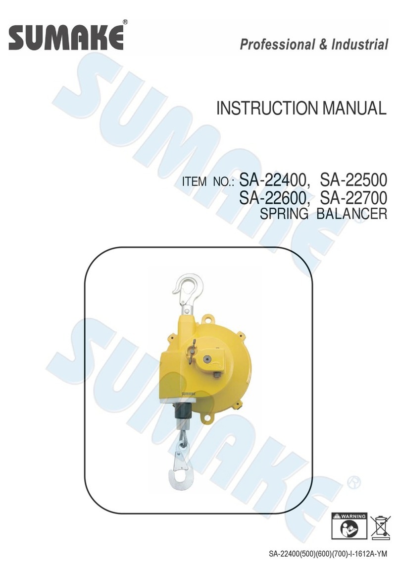
INSTRUCTION MANUAL
ITEM NO.: SA-22900
SPRING BALANCER (70-90KGS)
SA-221050
SPRING BALANCER (90-105KGS)
SA-221200
SPRING BALANCER (105-120KGS)
SA-22900(1050)(1200)-I-1911A-YM

2
1. Safety instruction
Never stand under the spring balancer.
Incorrect use of the spring balancer could cause personal injury.
Observe instruction in the manual and use the balancer correctly.
Never put the spring balancer in fluid.
Don’t twist and rub the cordage with cable during travel.
Don’t load over its capacity.

3
Take the tools off while remove the spring balancer, prevent the devise drop down.
Please remove the spring balancer and tools if rest for a long time.
Never remove device while the cable is pulled out. The rope will retract immediately and cause
personal injury
Large angle using will debase the wire rope's life, under ±20° is
better.
Install the safety support cable with suitable length to allow the balancer rotate freely and to stop balancer dropping in case
of original installment failure.

4
2. Description
(2.1) Specification
Model No.
Cable Travel (Kg)
Travel (M)
Weight (Kg)
SA-22900
70~90
2.0
22.2
SA-221050
85~105
2.0
23.75
SA-221200
100~120
2.0
27.4
(2.2) Working condition
Application area: indoor
Temperature range: -10°C ~ +50°C
(2.3) Mechanism Feature
Drop prevention device:
To prevent the suspended tool dropping in case of spring(6) broken. The safety pin(33) will pop out to stop
spring set (7)and stuck by safety stopper (15) the drum won't rotate. (see Fig.3)
This device can prevent tool dropping when spring broken.
Drum lock(13): (refer to chapter 6-1 "Drum Lock Operation”)
It could lock the drum per every 1/6 turns.
This mechanism is used to remove the suspended tool (refer to chapter 7) or replace wire cable (refer to
chapter 10).
or replace cable guide set (refer to chapter 12).
3. Installation
Please install the spring balancer correctly. The incorrect installation will cause personal injury or other
equipment damage.
Must attach a safety support cable or chain. In case of hanger failure cause balancer dropping .
(3.1) Prepare the fitting which can bear at least 10 times the maximum capacity of spring balancer.
NOTE : The fitting must be closed to prevent the balancer disengaging or dropping.
(3.2) Check whether the latch(24) is in closed condition after installing
NOTE : The spring balancer can not hit surrounding objects.
(3.3) Check whether the hanger(2) can swing.
NOTE : Please DO NOT fasten the hanger to fitting .
(3.4) Prepare a safety cable or chain that can bear at lease 10 times maximum capacity of spring balancer.
(3.5) Connect an end of safety cable or chain to loop to fix(46) and connect the other end to the stable position.
(3.6) Install the tool which is in capacity of spring balancer on hook.
(3.7) Please adjust the spring tension after installing tool.

5
4. Check before using
(4.1) The hanger(2) and hook(8) is stable and turn swivel .
(4.2) The cable set is completed and no any damaged .
(4.3) The stop pin(13) is in open position (see Fig.1) .
(4.4) The appearance is no damage
5. Spring Tension Adjustment
The original tension is in Min. Capacity if the spring tension is set under minimum capacity, the drop
prevention device will operate and the balancer is unable to use.
If the spring tension is set over maximum capacity, the spring balancer can't provide specified cable
travel and the spring life will be shortened .
Please check and adjust the setting before using. Turn worm gear (3) by +, - direction. (see P3. 2-1) and
check gauge(37).
(5.1) Please use wrench to adjust spring tension by turning worm gear. Turn clockwise is to increase (+) spring tension;
turn counter -clockwise is to reduce (-) spring tension and the gauge(37) will show current approximate spring
tension (see Fig.2)
(5.2) Lift the tool to engage the hook and lock it. Never pull the cable down to reach the tool
(5.3) Please re-check spring tension after attaching tool.
(5.4) Check the travel of spring balancer is enough for application or not. If it is not enough, please lower the mounting
height or insert the suitable fitting between hook and suspended tool.

6
6. Drum Lock Operation(5)(see Fig.1)
(6.1) Pull the stop pin (No.13) and turn clockwise to lock position And move the tool upward or downward until drum
become locked.
(6.2) Move the tool again to check the drum is locked securely then remove tool from hook.
Please check whether the stop pin is in lock position before removing suspended tool. The cable only
can move around 3~5 mm .(see Fig.1)
If the drum is not in lock position then the cable will retract back immediately and may cause personal
injury.
(6.3) If drum lock activate with cable pull out, please attach suitable weight tool before releasing drum lock.
(6.4) Please pull the stop pin (No.13) up then turn counter-clockwise then place it in open position. (see Fig.1)
Please DO NOT release drum lock if spring balancer unload or the weight of new tool is different with
old tool.
If release it, the cable will retract back immediately or the tool will drop down to cause personal injury.
For safety consideration, please adjust spring tension to fit suspended tool before releasing drum lock.
7. Tool/device Replacement
Method No.1--Replace tool by drum lock (13)
1. According chapter 6 "Drum Lock Operation", operator can remove suspended tool when stop pin in lock potion.
The operator can move tool upward and downward to check drum is locked securely.
If drum is not locked securely, the cable will retract back immediately and cause personal injury.
2. Please check the weight of new tool with all accessories is in capacity of spring balancer before attaching.
3. Please use wrench to adjust spring tension by turning worm gear. Turn clockwise is to increase (+) spring tension;
turn counterclockwise is to reduce (-) spring tension and the gauge will show current approximate spring tension.
(see P5, Fig.2)
4. Please release pin after attaching new tool.(see Fig.1)
Please DO NOT release drum lock before adjusting spring tension, if spring balancer unload or the
weight of new tool is different with old tool. If release it, the cable will retract back immediately or the
tool will drop down to cause personal injury.
5. Please re-adjust the spring tension after attaching new tool .
NOTE : Setting spring tension over maximum capacity may cause spring balancer or cable set damaged
Method No.2--Replace tool without locking drum (5)
Never remove suspended tool when cable is extended. Or the cable will retract back immediately to
cause personal injury.

7
1. The cable need to be retracted totally if operator needs to replace suspended tool.
2. Please adjust spring tension according chapter 5 "Spring Tension Adjustment" when attach the new tool.
8. Troubleshooting
Please stop operating if malfunction occur during operation immediately and take the necessary
step to check problem.
Please don't remove suspended tool before finding causes for safety reason. The cable could
retract back immediately and cause personal injury if removing tool without drum lock (13).
(8.1) Usual breakdown issue and causes:
Breakdown issue
Causes
Solution
A. Cable only can work approx. 5mm
Drum lock
Release drum lock
(refer to chapter 6)
B. Cable only can work approx.
100~130mm
Q1:Spring tension set under Min.
Release drop prevention device
(refer to chapter 8-2 Q1-A).
Q2:The drum lock is abnormal
Check drum lock (refer to chapter 8-2
Q2-A).
Q3:The spring broken.
Replace spring set (refer to chapter
11-1)
C. Cable can't pull or retract
The cable slipped off from truck and
stuck between drum and casing.
Make cable back to track.(refer to
chapter 8-3)
*Please contact with distributor if the above problem occur.
Careless repair may cause personal injury or spring balancer damaged, please be careful when
repair.
(8.2) Causes 8-1 B:
Q1. Spring tension is under Min. capacity of balancer that causes drop prevention device engaged.(see Fig.3
A: 1. Please install the spring balancer and hang the tool on hook.
2. Turn the worm gear(3) by clockwise to let tension fitting with suspended tool. Please refer to chapter
2-1.The drop prevention will release and start rising.
Q2: The drum lock is abnormal
A: 1. Please refer to Q1-A2, if the loading fit tension setting but cable still can't work. Then, it affirm the safety
pin(33) is abnormal. Due to cable can't go retract.
2. Make stop pin(13) to lock drum, release all screw(16) (don't dissemble cable guide), and remove safety
stopper (15).
3. The other person hold suspended tool then move stop pin(13) to open position
Operate by two persons for safety reason.
4. Move the tool upward and downward so the safety pin appears in the hole . (see Fig.3)
5. Check whether the safety pin(33) protrude from ring(11) surface. If yes, tape the safety pin by 5mm bar
lightly to let the safety pin inside the ring. (see Fig.3)

8
6. Check safety pin function before use: Lock drum by stop pin(5). Adjust the tension below capacity and
check whether the safety pin(33) pop out or not. Meanwhile. adjust the tension back to standard capacity and
check whether the safety pin move back inside the ring or not. If both yes, the balancer are available for use.
If any one is not, take out the spring seat set(7) according
7. To avoid ring(11) loosening, please use low-strength adhesives on thread. After reassembly, make sure the
ring is in a flat end to Chapter 11(sec.2 to 9) to check whether the safety pin spring (12)(44) is broken, remove
the dirt, and then reassemble and check again.(see.P10. 3) with its base.
Q3: The spring broken
A: 1. Refer to Q2-A5, if the safety pin(33) can't be retracted, It means the spring (6) is broken.
2. Refer to chapter 11 (sec.13~18)
If the installation of safety pin(33) and (15) is incorrect, the drop prevention device will not operate
when spring broken. This could cause personal injury or equipment damaged.
(8.3) Causes C :
■ When the cable stuck between drum and casing.
A: 1. To release the wire by pull strongly and quickly if the tool is suspended.
Check the cable is damaged or not after pulling, please replace if damaged. (see Chapter 10)

9
2. Please disassembly if the cable can't be release by pulling.
3. Turn stop pin at lock position(see P4 Fig.1), remove E snap (32) from worm gear. (3) (P5 Chapter 2)
4. Turn worm gear (3) counter-clockwise to release spring tension and remove it.
5. Remove the tool from hook then remove spring balancer.
6. Remove cable guide (17&18) from casing. (1)
7. Remove screw (16) then release all safety stopper. (15)
8. Release screw (36) and cover (9) after releasing gauge.(37)
9. Make the cable to the truck of drum (5) Replace cable if damaged .
10. Install the cover (9), worm gear (3) and E snap (32) .
11. Adjust the spring tension and install gauge (37), safety stopper (15), cable guide (17&18).
Please refer Chapter 11"Spring Replacement" (sec.13~18).
9. Inspections
Periodically inspect the spring balancer and replace the Must use the original part to replace.
Inspect the spring balancer per month at least. Repair it if any problem detected. Please short the inspection
interval time if frequently operation or hostile environment.(Fig.4)

10
10. Cable Replacement
(10.1) 10-1 Pull the tool downward and extend the cable to Max. travel.
(10.2) According Fig.5, adjust the screw (27) and turn stop pin (3) at lock position, refer to chapter 6-1.P6
(10.3) Move the tool upward and downward to make sure the drum is locked then remove tool from hook.

11
Never remove the suspended tool before drum is locked securely.
If drum is not locked securely, the cable may retract or the drum will rotate suddenly and possible to
case personal injury.
(10.4) Remove the spring balancer from fitting and put on stable position.
(10.5) Turn worm gear (3) counter-clockwise to release spring tension, check whether the cable only can move for
5mm by manual. (drop prevention device activated)
(10.6) Release screw (27) and pull out the old cable from drum, if the cable stuck inside of drum, push the tip of cable
into the drum
(10.7) Insert the new cable to from "A" to "B" hole and through drum. If can't be through the drum cause cable stuck
inside of it, press and twist. The cable will go through to drum by this method.
(10.8) Install the end of cable to drum and fasten by screw (27).
(10.9) Install the Spring Balancer to the suitable position and refer to chapter 3.
Please check and adjust the setting before using. Note to turn worm gear (3) by "+" direction.
Please don't release drum lock before installing suspended tool. If released, the cable will be
retracted suddenly then cause personal injury.
(10.10) Affirm the loading fit spring tension setting, pull the stop pin (13) by counter-clockwise to open position to work.
11. Spring Replacement
Pleases don't take spring from spring plate otherwise the spring will expand explosively and cause
personal injury.
Replace the spring plate by complete set. (7)
Refer to the drawing, for disassemble the spring balancer by the steps.
(11.1)
A. When spring broken, the drum will lock by pop out safety pin (33). The available move space of cable will be
between two safety stopper (15). Please disassembly the suspended tool from hook to replace spring plate.
(7)
Three spring type: SA-22900, SA-221050
Four spring type: SA-22120
SA-22900, SA-221050, SA-22120 has three or four springs, so some spring tension remains even
one spring broken. be careful and note when disassembly.
Please refer to Chapter 6-1"Drum Lock Operation" and lock it then remove suspended tool from Hook.
B. If the spring is not broken completely, made the cable retract to drum (5) and remove tool from Hook.
(11.2) Remove Spring Balancer from fitting and place on stable table.
(11.3) Remove gauge.

12
(11.4) Remove E snap(32) from Worm Gear (3), release spring tension by turning worm gear counter clockwise unitl
worm gear can be removed. Make sure there is no spring tension remaining then release drum lock.
NOTE: To check spring tension by pulling cable.
(11.5) Turn the worm gear(3) by counter clockwise then remove it out.
(11.6) Remove cable guide set (17&18) from casing
NOTE: The screw (19) is sealed to avoid loosen, please use new screw with adhesive after replacing .
(11.7) Release screw (16) and all safety stopper (15).
(11.8) Remove screw (36), open cover (9).
(11.9) Remove spindle(4). Spring plate(7) and Drum(5) form casing .
(11.10) Remove spindle(4).
(11.11) Disassemble spring plate (7) and screw (31) of drum (5).
(11.12) Remove spindle sleeve (29) from spring plate set (7).
Do Not disassemble spring cover (No. 28) from spring plate (No.7); If removed, the internal spring will
pop s out and cause personal injury.
(11.13) Assemble by opposite steps
(11.14) Install the cable guide set (17&18) to casing (1)
NOTE: The screw (No.9) is sealed to avoid looseness, please use new screw if removed. The suitable
torque range is 2.8~3.0 Nm (28~30 kg.cm).
(11.15) Turn worm gear clockwise to wind the cable to drum track.
NOTE: The cable will retract to drum if turn worm gear. Please note the cable can not slip out from drum
track. Turn worm by the number of turns a below after cable fully retract. Meanwhile the safety pin (33)
retract.
Model No.
Turns
SA-22900
95
SA-221050
95
SA-221200
95
(11.16) Install the tool which weight is in capacity of spring balancer and adjust the spring tension.
(11.17) Install the gauge and adjust
(11.18) Install the safety stopper (15) to casing (1). (refer to Fig.7), use the screw (16) to tighten safety stopper (15).
If installation of Safety stopper (15) is incorrect or missing, the drop prevention device will not operate
when spring broken. It could cause personal injury or equipment damaged.

13
12. Cable Guide Replacement
(12.1) Pull out the cable which cable guide set is available to replace and lock drum by stop pin (13). (refer to Fig.8)
(12.2) Confirm the stop pin at lock position by move suspended tool up and down then take it off .
Never remove the suspended tool before checking Drum is locked. If Drum is not locked securely, the
cable will retract back or drum rotate suddenly. And possibly to case personal injury.
(12.3) Remove the balancer from a fitting and place on the table.
(12.4) Remove the screw (19) and cable guide set (17&18).
(12.5) Install new cable guide set (17&18).
NOTE : Screw(19) are sealed against looseness, please replace old one with new ones when removed.
Tighten the screw with torque 2.8 - 3.0 Nm {28 - 30 Kgf.cm}.
(12.6) Install the Spring Balancer on a fitting.
(12.7) Attach the tool to bottom hook and release the drum lock, by turn stop pin(13) counter clockwise.
Never release the drum lock before attaching the tool. If released, the cable will retract back and could
cause personal injury.
ECDECLARATION OF CONFORMITY
We: SUMAKE INDUSTRIAL CO., LTD.
4F, No. 351, Yangguang St., Neihu District, Taipei City, Taiwan
declare in sole responsibility that the equipment
Equipment:SPRING BALANCER
Model/ Serial No.:SA-22900, SA-221050, SA-221200
to which this declaration applies, complies with these normative documents:
Machinery Directive: 2006/42/EC
and conforms to the following EN standard,
EN ISO 12100: 2010
Name and Signature/Position Date and Place
2018/9/14
MikeSu–ManagingDirector Taipei, Taiwan
SA-22900(1050)(1200)-D-1911A-YMF

SPRING BALANCER (70-90KGS)
SPRING BALANCER (90-105KGS)
SPRING BALANCER (105-120KGS)
SA-22900
SA-221050
SA-221200
PARTS LIST
No. Parts No. Descri
p
tion Q't
y
No. Parts No. Descri
p
tion Q't
y
20 SA22900-20 Sheath 2
26 SA22900-26 Bearin
g
2
3 SA22900-03 Worm Gear 1 27 SA22900-27 Screw 1
SA22900-04 S
p
indle
[
SA-22900
]
1 SA22900-29 S
p
indle Sleeve
[
SA-22900
]
1
SA221050-04 S
p
indle
[
SA-221050
]
1 SA221050-29 S
p
indle Sleeve
[
SA-221050
]
1
SA221200-04 S
p
indle
[
SA-221200
]
1 SA221200-29 S
p
indle Sleeve
[
SA-221200
]
1
SA22900-05 Drum
[
SA-22900
]
1 30 SA22900-30 S
p
rin
g
Washer 12
SA221050-05 Drum
[
SA-221050
]
1 31 SA22900-31 Screw 5
SA221200-05 Drum
[
SA-221200
]
1 32 SA22900-32 T
yp
e E Sna
p
1
S
p
rin
g
Set
[
SA-22900
]
33 SA22900-33 S
p
rin
g
Pin 1
[
Incl. 6
(
3
)
, 7, 28
]
34 SA22900-34 Rubber Sto
p
1
S
p
rin
g
Set
[
SA-221050
]
35 SA22900-35
A
liuminum Head 1
[
Incl. 6
(
3
)
, 7, 28
]
36 SA22900-36 Screw 6
S
p
rin
g
Set
[
SA-221200
]
37 SA22900-37 Gau
g
e 1
[
Incl. 6
(
4
)
, 7, 28
]
38 SA22900-38 Screw 1
SA22900-08 Cable Set
[
SA-22900
]
1 39 - Lable 1
SA221050-08 Cable Set
[
SA-221050
]
1 40 - Lable 1
SA221200-08 Cable Set
[
SA-221200
]
1 41 SA22900-41 Shaft 1
9 SA22900-09 Cover Assemlb
y
[
Incl. 9, 10
]
1 42 SA22900-42 Worm Wheel Axos 1
11 SA22900-11 Rin
g
2 43 SA22900-43 Ke
y
1
12 SA22900-12 S
p
rin
g
2 44 SA22900-44 S
p
rin
g
1
13 SA22900-13 Sto
p
Pin 1 45 SA22900-45 Bushin
g
1
14 SA22900-14 S
p
rin
g
Pin 1 46 SA22900-46 Loo
p
To Fix 1
15 SA22900-15 Safet
y
Sto
pp
er 4 47 SA22900-47 Baffle 1
16
S 22900 16
S
8
8
S 22900 8
1
8
1
1
1
SA22900-06S
SA221050-06S
5
SA221200-06S 1
6
294
Casing Set [Incl. 1, 2, 21, 22,
23, 24, 25
]
1 SA22900-01S
16 SA22900-16 Screw 8 48 SA22900-48 Bearin
g
1
17 SA22900-17 Cable Guide 2 49 SA22900-49 Nut 6
18 SA22900-18
A
liuminum Tube 2 50 SA22900-50 T
yp
e C Sna
p
2
19 SA22900-19 Screw 2 52 SA22900-52 Screw 1
SA-22900
(
1050
)(
1200
)
-P-1911A-YM

NOTE
www.SUMAKE.com
www.AIRCOMPRESSOR.com.tw
This manual suits for next models
2
Table of contents
Other Sumake Lifting System manuals
Popular Lifting System manuals by other brands

BVA Hydraulics
BVA Hydraulics HD20013 instruction manual

Mobile Industrial Robots
Mobile Industrial Robots MiR500 user guide

Vestil
Vestil FLB-D Series instruction manual

Aqua Creek Products
Aqua Creek Products Ambassador F-PPXRD-R-04 manual

Braun
Braun Century NCL Series Service manual

Austlift
Austlift 915210 Service manual

GYS
GYS LUXMAIN QUICK LIFT L520E Operating and control manual

EKKO
EKKO Walkie EB16EA manual

Ravaglioli
Ravaglioli KPS305H Translation of the original instructions

Triumph
Triumph NTO-9AE ASSEMBLY & OPERATION INSTRUCTION

SPX
SPX 1525 operating instructions

S.R.Smith
S.R.Smith aXs Series Owners manual & maintenance procedures