LIFTINGITALIA DomoFlex MM13 Guide

1(24)
LIFTINGITALIA S.r.l.
IM.TEC.077.IT_rev.2 - May 2019
EN
MM13 control cabinet - Installaon and diagnoscs
sample image
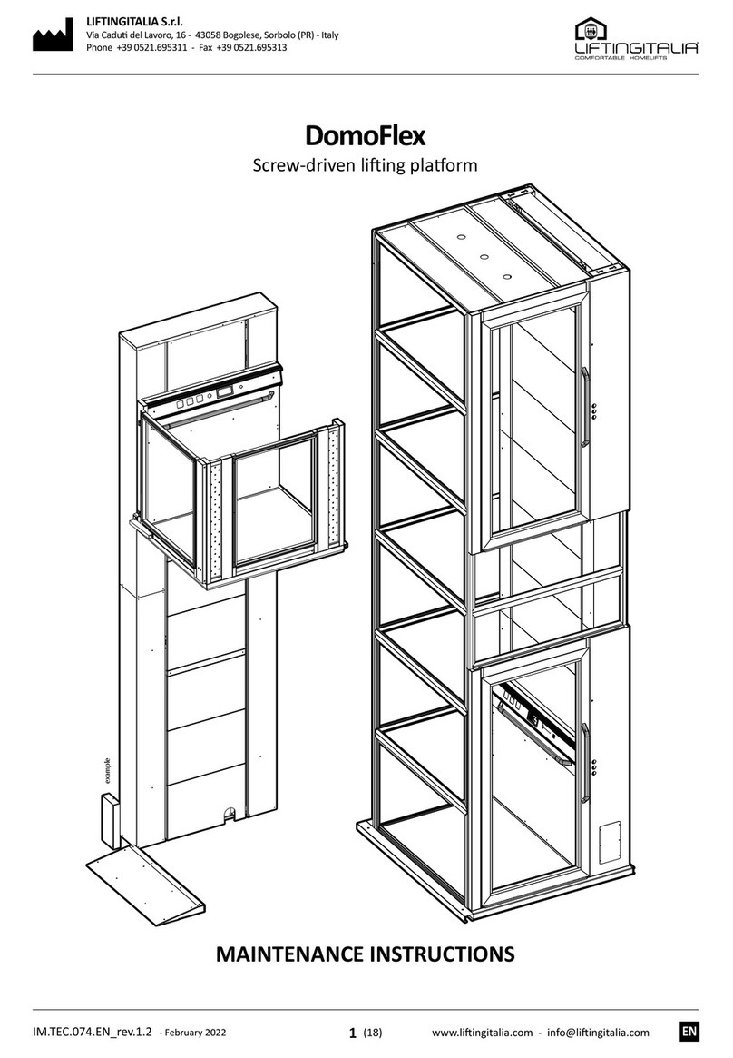
DomoFlex
Screw-driven liing plaorm
MM13 CONTROL CABINET
INSTALLATION AND DIAGNOSTICS

2(24)
LIFTINGITALIA S.r.l.
20190525
IM.TEC.077.IT_rev.2 - May 2019
EN
2General update 25.05.2019
1General modicaons for on-board panel inseron 18.09.2017
Rev. Descripon Data

3(24) All rights reserved
IM.TEC.077.IT_rev.2 - May 2019
EN
DomoFlex - Electric screw driven plaorm li
MM13 CONTROL CABINET- INSTALLATION AND DIAGNOSTICS
1. GENERAL DISPOSITIONS AND INSTALLATION SITE MANAGEMENT ................................................6
1.1. GENERAL DISPOSITIONS.................................................................................6
2. PRELIMINARY CONTROLS...................................................................................7
2.1. PRELIMINARY SAFETY CHEKS.............................................................................7
2.2. PRELIMINARY CHECKS OF THE INSTALLATION SITE ..........................................................7
2.3. OBLIGATIONS OF THE INSTALLER .........................................................................7
3. PRODUCT DESCRIPTION....................................................................................8
3.1. GENERAL DESCRIPTION AND TERMINOLOGY ...............................................................8
3.1. DESCRIZIONE GENERALE E TERMINOLOGIA ................................................................8
4. MM13 CONTROL CABINET - PRINCIPAL COMPONENTS..........................................................9
4.1. SWITCHING POWER SUPPLY, CBE5901 and CBE5902.........................................................9
4.2. ELECTROMOTIVE FORCE PANEL WITH MAINTENANCE AND EMERGENCY CONTROLS.............................9
4.3. ITF232 - SERIAL INTERFACE CARD . . . . . . . . . . . . . . . . . . . . . . . . . . . . . . . . . . . . . . . . . . . . . . . . . . . . . . . . . . . . . . . . . . . . . . . .10
4.4. ITF800 - FLOOR AND CAR SERIAL CARD ...................................................................10
5. FIRST RUN CONNECTION ..................................................................................11
6. MAGNETS LAYOUT .......................................................................................12
6.1. STOP AND SLOW-DOWN MAGNETS ......................................................................12
7. INSULATION TESTS .......................................................................................15
8. PLC INPUT / OUTPUT DIAGNOSTICS .........................................................................16
9. DIAGNOSTICS BY MEANS OF BLINKING CODE.................................................................24
INDEX

4(24)
LIFTINGITALIA S.r.l.
IM.TEC.077.IT_rev.2 - May 2019
EN
SCOPO DEL MANUALE
SICUREZZA PERSONALE E RICONOSCIMENTO DEL RISCHIO
RISK SYMBOLOGY AND PHRASES
NOTICE
READ THIS MANUAL CAREFULLY before installing and using the product. This product must
FOLLOW THE SUGGESTIONS AND RECOMMENDATIONS TO OPERATE IN SAFETY.
QUALIFIED PERSONNEL:
RISK CLASSIFICATION AND RELATIVE GRAVITY OF DAMAGE
DANGER
causes
WARNING The symbol indicates that the failure to observe the corresponding safety
measures can cause death or serious personal injury.
CAUTION The symbol indicates that failure to observe the relevant safety measures can
cause minor or moderate personal injury or damage to the device.
NOTICE It is not a symbol of security. It indicates that the failure to comply with relevant
safety measures can result in property damage.
INFORMATION
descending order.
PURPOSE OF THE MANUAL
PERSONAL SECURITY AND RISK RECOGNITION
NOTE:
.
RISK LEVEL

5(24) All rights reserved
IM.TEC.077.IT_rev.2 - May 2019
EN
DomoFlex - Electric screw driven plaorm li
MM13 CONTROL CABINET- INSTALLATION AND DIAGNOSTICS
GUIDA ALLA LETTURA DEL MANUALE
RESPONSABILITÀ E CONDIZIONI DI GARANZIA:
GENERAL DANGER ELECTRICITY DANGER DANGER FLAMMABLE MATERIAL
DANGER OF FALL BY A LEVEL DANGER SUSPENDED LOADS DANGER CORROSIVE SUBSTANCES
OBLIGATIORY TO WEAR THE
PROTECTION HELMET
OBLIGATORY TO WEAR SAFETY
SHOES
OBLIGATORY WEAR THE PROTECTIVE
GLOVES
OBLIGATORY TO WEAR EYE
PROTECTION
OBLIGATION TO WEAR THE AUDIO
PROTECTION OBLIGATORY TO WEAR THE MASK
OBLIGATORY TO WEAR PROTECTIVE
CLOTHES OBLIGATORY TO KEEP CLOSED OBLIGATORY TO CHECK THE
PROTECTIONS
GENERIC PROHIBITION FORBIDDEN TO STEP ON PROHIBITED TO WALK ON OR STOP
IN THIS AREA
WARNING SIGN
MANDATORY SIGN
PROHIBITION SIGN
EMERGENCY AND FIRST AID SIGNS INDICATION SYMBOLS
RESPONSIBILITY OF THE INSTALLER
MANUAL READING GUIDE
LIABILITY AND WARRANTY CONDITIONS:
NOTA BENE KEEP DRY OBLIGATORY TO CHECK
THE PROTECTIONS
FIRST AID
NOTE:

6(24)
LIFTINGITALIA S.r.l.
1. DISPOSIZIONI GENERALI E GESTIONE DEL CANTIERE
1.1. DISPOSIZIONI GENERALI
IM.TEC.077.IT_rev.2 - May 2019
EN
2 x
MAX 50 kg
> 50 kg
IMPORTANT!
SAFETY IN-
STRUCTIONS AND SITE MANAGEMENT
NOTICE
PRELIMINARY CHECKS:
CAUTION
SAFETY AND SITE MANAGEMENT - OVERALL DISPOSITIONS:
1.
2.
3.
•
•
•
this manual.
•
•
The assembly must be
performed by a MINIMUM 2
people;
If the load is greater than 50kg, use the hoist
for handling.
NOTE:
that connects its slabs.
GENERAL DISPOSITIONS AND INSTALLATION SITE MANAGEMENT
GENERAL DISPOSITIONS
WARNING
RISK OF ELECTROCUTION:
The lighng and power supply systems must meet the requirements of the system and the
regulaons in force. Check that it has an eecve earth. If they do not meet all the requirements,
interrupt the installaon unl the system has been brought up to standard by the customer.

7(24)
2. VERIFICHE PRELIMINARI
2.1. VERIFICHE PRELIMINARI DI SICUREZZA
2.2. VERIFICHE PRELIMINARI DEL LUOGO DI INSTALLAZIONE
2.3. OBBLIGHI DELL'INSTALLATORE
All rights reserved
IM.TEC.077.IT_rev.2 - May 2019
EN
DomoFlex - Electric screw driven plaorm li
MM13 CONTROL CABINET- INSTALLATION AND DIAGNOSTICS
PRELIMINARY CONTROLS
PRELIMINARY SAFETY CHECKS
PRELIMINARY CHECKS OF THE INSTALLATION SITE
OBLIGATIONS OF THE INSTALLER
WARNING
BEFORE STARTING THE INSTALLATION, YOU NEED:
•
grounding;
up-to-date.
•
•
•
•
•
BEFORE STARTING THE INSTALLATION, YOU NEED:
•
•
•
•
•
•
NOTICE
BEFORE STARTING THE INSTALLATION CHECK THE FOLLOWING MEASURES AND COMPARE THEM WITH
THOSE ON THE PROJECT DRAWING:
• Width (distance between the side walls)
•
• Pit depth
• Travel
•
•
•
•
measurements taken by the building manufacturers.

8(24)
LIFTINGITALIA S.r.l.
3. DESCRIZIONE PRODOTTO
3.1. DESCRIZIONE GENERALE E TERMINOLOGIA
IM.TEC.077.IT_rev.2 - May 2019
EN
The electrical equipment of the domoFLEX li is designed on the purpose to obtain the best possible integraon between the elec-
trical and mechanical parts. The main electrical components are as follows:
a. microprocessor card capable of communicang, through the serial
interface card, directly with the buons and signals in use;
b. pre-wired compartment electric lines: made with double sheath
cable and shunt boxes; quick installaon system that does not
require the laying of a conduit;
c. car pre-wired electric lines: composed of exible at cables alrea-
dy connected to the edge of the machine; only the connecon
with the box in the pit is required.
PRODUCT DESCRIPTION
GENERAL DESCRIPTION AND TERMINOLOGY
INFORMATION

9(24)
1
4a
2
4b
4c
4d
4e
1
4a
4b
4c
4d
4e
2
1
2
1
3
23 4
4
5
5
4. COMPONENTI PRINCIPALI QUADRO MM13
4.1. ALIMENTAZIONE SWITCHING, CBE5901 e CBE5902
4.2. QUADRO DI FORZA ELETTROMOTRICE CON COMANDI DI MANUTENZIONE ED EMERGENZA
All rights reserved
IM.TEC.077.IT_rev.2 - May 2019
EN
DomoFlex - Electric screw driven plaorm li
MM13 CONTROL CABINET- INSTALLATION AND DIAGNOSTICS
This paragraph is meant to describe the funcons of the principal devices of the electrical cabinet, the aenon being focused on
the problem solving aspects.
Receives mains voltage in input.
Generates a 24VDC voltage for auxiliary ulies.
Diagnosc Led:
a) Unplugged or at baery
b) 12V voltage present
c) Mains voltage present
d) Mains voltage present
e) Emergency power supply acve
The MAINTENANCE / NORMAL MODE switch allows to shi from normal mode
to maintenance and vice versa; every me you shi from maintenance to normal
mode it is necessary to perform a reset by pressing both up and down buons for
more than 3 seconds.
Ascending buon UP: in maintenance and normal mode it commands the ascent
when kept pressed.
Central buon DOWN EMERGENCY (red): it forces a manual emergency manoeuvre.
When acvated, the safety devices are opened and the card is locked (RESET NECES-
SARY to restore normal operaon).
MM13 CONTROL CABINET - PRINCIPAL COMPONENTS
SWITCHING POWER SUPPLY, CBE5901 and CBE5902
ELECTROMOTIVE FORCE PANEL WITH MAINTENANCE AND EMERGENCY CONTROLS
INFORMATION
Descending buon DOWN: in maintenance and normal mode it commands the
descent when kept pressed.
The DOOR ZONE warning light indicates the presence of the plaorm on the oor
and ashes in the event of a failure.
WARNING
DANGER OF CRUSHING: No safety device is acve while the buon is pressed!

10 (24)
LIFTINGITALIA S.r.l.
S T 4
S T 3
S T 2
S T 1
5V
S E L E C T E NT E R
R E S E T
+V
G ND
C LO C K
DAT O
I1
I2
I3I4
O 1
O2
O 3O 4
DL1 DL 2
DL3
DL4
J 4
J 3
J 1
J 2
B Z1
JP
4.3. ITF232 - SCHEDA DI INTERFACCIA SERIALE
4.4. ITF800 - SCHEDA SERIALE DI PIANO E CABINA
IM.TEC.077.IT_rev.2 - May 2019
EN
It manages the compartment and car serial communicaon bus allowing the card
to communicate directly with the serial components in use (connecons on wiring
diagrams).
Diagnosc Led:
a. 5V: power supply presence;
b. ST1, ST2: not used;
c. ST3: PLC connected if 1 second on and 1 second o;
d. ST4: card connected if 1 second on and 1 second o.
It manages the oor and car buons and signals (connecons on wiring
diagram).
Diagnosc Led:
a. DL1: correct operaon if 1 sec on and 1 sec o; fast ashing if jumper
inserted, interrupted or incorrect serial connecons;
b. DL2: if it ashes slowly, the card is programmed; the number of ashes
between two long pauses indicates the code;
c. DL3: on if J1 connector contact is closed;
d. DL4: on if J1 connector contact is closed.
Programming procedure:
e. insert the jumper (JP); DL1 ashes quickly;
f. to enter the address press the buon the same number of mes as the
oor: once for the lowest oor, twice for the next, etc.
g. remove the jumper to store the address;
h. to check the address, count the number of ashes of the DL2 LED.
ITF232 - SERIAL INTERFACE CARD
ITF800 - FLOOR AND CAR SERIAL CARD

11 (24)
5. COLLEGAMENTI PER IL PRIMO AVVIAMENTO
All rights reserved
IM.TEC.077.IT_rev.2 - May 2019
EN
DomoFlex - Electric screw driven plaorm li
MM13 CONTROL CABINET- INSTALLATION AND DIAGNOSTICS
a. The card is supplied with electrical bridges on the XQ1, XQ14 and XQ17 terminals for the rst movement in maintenance mode
using the 0 and 1 buons present on the plaorm pushbuon panel.
b. Connect a temporary 230Vac single phase power cable to the L, N, PE terminals present on the machine panel.
FIRST RUN CONNECTION
INFORMATION
To activate the movement of the machine, press button 1 for an ascent and button 0 for a descent.
CAUTION
The ascent command in maintenance mode has no electrical or
mechanical limit, so the machine will stop only when the buon
is released or when the STOP buon on the plaorm pushbuon
panel is pressed.
The descent-run is limited by the stop magnets P0 that are placed
in the test phase.
CAUTION
Make all earthing connecons.

12 (24)
LIFTINGITALIA S.r.l.
6.1. MAGNETI DI FERMATA E RALLENTAMENTO
6. DISPOSIZIONE MAGNETI
IM.TEC.077.IT_rev.2 - May 2019
EN
1. With the system under maintenance, bring the car to the exact oor level (oor and car levels aligned);
2. IS ascent sensor: gradually move from the top the 150 mm magnet towards the sensor, stopping just as the corresponding I13 LED on the card turns on;
3. ID descent sensor: gradually move from the boom the 150 mm magnet to the sensor, stopping just as the corresponding I11 LED on the card turns on.
MAGNETS LAYOUT
STOP AND SLOW-DOWN MAGNETS
INFORMATION
Two assemblers are needed:: one in the machine room in front of the control panel and the other near the
sensors.

13 (24)
IR IS
ID
KIT E202.23.0002
All rights reserved
IM.TEC.077.IT_rev.2 - May 2019
EN
DomoFlex - Electric screw driven plaorm li
MM13 CONTROL CABINET- INSTALLATION AND DIAGNOSTICS
LEGEND
IR Re-phasing sensor
ID Descent sensor (stop and slowdown)
IS Ascent sensor (stop and slowdown)
PB Lowest oor
PI Intermediate oors
PA Upper oor
ZB Bypass zone
Rall. Slowdown distance
Hereunder, the recommended sensor locaon.

14 (24)
LIFTINGITALIA S.r.l.
Rall.Rall.Rall.Rall.Rall.
150
PA
PI
PB
IR IS ID
ZB
PA
PI
PB
ZB
ZBZB
ZBZB
IM.TEC.077.IT_rev.2 - May 2019
EN

15 (24)
7. PROVE DI ISOLAMENTO
All rights reserved
IM.TEC.077.IT_rev.2 - May 2019
EN
DomoFlex - Electric screw driven plaorm li
MM13 CONTROL CABINET- INSTALLATION AND DIAGNOSTICS
• Posion the car between two oors and check if the safety chain is closed.
• Disconnect the electrical cabinet from the mains supply by opening all the switches of the power supply board.
• Disconnect al the baery terminals
• Disconnect all the users connecng the PE conductor by means of power supply clamps.
• Measure the resistance values between the terminals indicated in the below table. The table shows the test power (V) and the
minimum resistance of the insulaon between the circuits (MΩ).
-L1 (L2, L3) LC-L LV-L + 24 V + 12 V
PE 500 V
> 1 MΩ
500 V
> 1 MΩ
500 V
> 1 MΩ
250 V
> 0,5 MΩ
250 V
> 0,5 MΩ
L1 (L2, L3) -500 V
> 1 MΩ
500 V
> 1 MΩ
500 V
> 1 MΩ
500 V
> 1 MΩ
LC-L - - 500 V
> 1 MΩ
500 V
> 1 MΩ
500 V
> 1 MΩ
• On test compleon restore the inial state of the connecons.
INSULATION TESTS

16 (24)
LIFTINGITALIA S.r.l.
XQ16
XQ7
XQ4
XQ1
XQ8
XQ9
XQ10
XQ11
XQ12
XQ13
XQ14
XQ15
XQ17
XQ18 XQ19
RS485
B
IP0
BUZZER
ON
XQ2
XQ5
XQ6 XQ3
24
1
1
1
4
1
1
1
1
1
4
1
1
1
1
8
1
6
10
1
1
12
1
3 2 1 21 4321
KCH0 KAP0 KA-ELT
KA-BR2 KA-BR1
KA-SIC1
KA-SIC2
24Vdc
RESET
TM
RS232-485
F0 5x20
F1 5x20
I23
I22
O10
O9
O8
O7
O6
I24
I21
I20
O5 O4 O17
O16
O13
I25
I10
I6
I5
I4
I3
I2
I1
I8
I7
I9
O2
O1
I14I13I12 I11 I16I15
I18 I17
8. DIAGNOSTICA INGRESSI / USCITE
IM.TEC.077.IT_rev.2 - May 2019
EN
To check the status of the logic signals on the card, refer to the LEDs located in the respecve terminals.
Each led is idened by a name to make reading easier:
• I = INPUT;
• O = OUTPUT;
are accompanied by a plate that has a short acronym to help idenfy the funcon.
CONTROL PROCEDURE ON FIRST START-UP
• Bring the car to the boom oor;
• Close all doors and all safety devices, so that the system is ready to be called (system on Standby);
• Move the MAINTENANCE / NORMAL MODE switch to the NORMAL MODE posion and reset by pressing UP and DOWN for
more than 3 seconds;
• The status of the card must be as shown in the INPUT table.
• Below is an example diagram to help recognise inputs and outputs.
• Check all card inputs using the indicaons in the following table; if the input status does not match, follow the indicaons given
in the row "IF STATUS NOT CORRECT".
PLC INPUT / OUTPUT DIAGNOSTICS

17 (24) All rights reserved
IM.TEC.077.IT_rev.2 - May 2019
EN
DomoFlex - Electric screw driven plaorm li
MM13 CONTROL CABINET- INSTALLATION AND DIAGNOSTICS
LED KEY
INPUT
(LED) SIGNAL ELETTRICAL
DIAGRAM
I1 PIT SAFETY AND EMERGENCY
BUTTON
SB_PEF;
SQ_FF;
SB_MEM
I2 OVERTRAVEL SAFETY DEVICE SQ_EXC
I3 CAR SAFETY DEVICES
SB_PEC;
SQ_BOR;
SQ_COL;
SQ_MAD;
SQ_PER
I4 CAR GATE SAFETY DEVICE SQ_APC;
SQ_ABC
I5 FLOOR PRELIMINARY CONTACTS
SAFETY DEVICES SQ_APP
I6 LOCKS SAFETY SQ_ABP
I7 NOT_USED
I8 CAR CALL DISABLING SA_CAB
I9 RESERVED FUNCTION XQ4.8
I10 OVERLOAD SENSOR SQ_OVL
I11 DESCENT MAGNETIC SENSOR ID
I12 CORRECTION MAGNETIC SENSOR IR
I13 ASCENT MAGNETIC SENSOR IS
I14 NOT_USED
I15 NOT_USED
I16 NOT_USED
I17 MAINS VOLTAGE FAILURE EM
I18 BATTERY CHARGED BAT
I20 FLOOR CALLS DISABLING XQ1.9
I21 PIT DOOR ACCESS UNLOCKED SQ_SPF
I22 MANUAL DESCENT COMMAND SB_DN
I23 MANUAL ASCENT COMMAND SB_UP
I24 NORMAL MODE SWITCH SA_AUT
I25 SCREW LIFTING AND BOTTOM
SENSOR
SQ_FON/
SQ_VIT
I26 INVERTER FAULT INV FAULT
I27 INVERTER SECURITY INV SEC
I28 INVERTER BRAKE INV BRAKE
OUTPUT
(LED) SIGNAL ELETTRICAL
DIAGRAM
O1 OVERLOAD FAULT SIGNAL HL_OVL
O2 OCCUPIED LIGHT HL_CAB
O3 NOT_USED
O4 PLATFORM DOOR OPENING KAP0
O5 PLATFORM DOOR CLOSURE KCH0
O6 EMERGENCY BUTTON SB_MEM
O7 FLOOR LED (FLOOR ZONE) HL_PIA
O8 PIT ACCESS SIGNAL HL_SPF
O9 FLOOR DOORS OPENING KAP1
O10 FLOOR DOORS CLOSURE KCH1
O13 SAFETY CHAIN MOVEMENT CON-
SENT
KASIC1 -
KASIC2
O16 BRAKE COMMAND KABR1 -
KABR2
O17 ELECTRIC LOCK COMMAND KAELT

18 (24)
LIFTINGITALIA S.r.l.
IM.TEC.077.IT_rev.2 - May 2019
EN
INPUTS
I1 Label PIT SAFETY AND EMERGENCY BUTTON
Descripon It deacvates if one of the pit safety devices or the manual emergency descent buon are
triggered.
STANDBY only ON
SQ_PER closed and SQ_FF closed and SB_MEM closed
INCORRECT STATUS a. check that the pit stop safety device has not triggered, SB_PEF terminal XF7;
b. check that the safety feature given by the pit safety device has not triggered, SQ_FF terminal
XF6;
c. check that the safety feature provided by the emergency buon on the FEM panel has not
triggered, SB_MEM terminal XF9.
I2 Label OVERTRAVEL SAFETY DEVICE
Descripon It deacvates if the overtravel contact is triggered.
STANDBY only ON
SQ_EXC closed
INCORRECT STATUS a. check the car posion and that SQ_EXC is not acvated;
b. check the wiring on the XQ8 terminal.
I3 Label CAR SAFETY DEVICES
Descripon The car deacvates if one of its safety devices is triggered
STANDBY only ON
SQ_PER closed and SQ_BOR closed and SQ_MAD closed and SB_PEC closed and SQ_COL closed
INCORRECT STATUS a. check that perimeter safety device has not triggered, SQ_PER terminal XQ12;
b. check that the edge safety device (above the plaorm pushbuon panel) has not triggered,
SQ_BOR terminal XQ9;
c. check that the safety device on the wear of the lead screw (near the screw oiler) has not trigge-
red, SQ_MAD terminal XQ11;
d. check that the safety feature provided by the stop buon has not triggered, SQ_PEC terminal
XQ4;
e. check that the safety feature provided by the cover panel (under the plaorm pushbuon
panel) has not triggered, SQ_COL terminal XQ10.
I4 Label CAR GATE SAFETY DEVICE
Descripon It deacvates if the gate stays open
STANDBY only ON
SQ_APC closed and SQ_ABC closed
INCORRECT STATUS Check that safety contacts of the gate are closed.
I5 Label FLOOR PRELIMINARY CONTACTS SAFETY DEVICES
Descripon It deacvates if one of the oor doors is open.
STANDBY only ON
SQ_APP closed
INCORRECT STATUS Check that all oor doors are closed and that all preliminary contacts are closed SQ_APP termi-
nal XF2.5 and XF2.6.

19 (24) All rights reserved
IM.TEC.077.IT_rev.2 - May 2019
EN
DomoFlex - Electric screw driven plaorm li
MM13 CONTROL CABINET- INSTALLATION AND DIAGNOSTICS
I6 Label LOCKS SAFETY
Descripon It deacvates if one of the oor doors is unlocked.
STANDBY only ON
SQ_ABP closed
INCORRECT STATUS Check that all oor doors are closed and that all preliminary contacts are closed SQ_APP termi-
nal XF2.7 and XF2.8.
I8 Label CAR CALL DISABLING
Descripon Acve if connected to +24V
STANDBY only ON if car calls are disabled;
OFF if car calls are enabled.
I10 Label OVERLOAD SENSOR
Descripon It acvates if the overload sensor is triggered.
STANDBY only OFF
SQ-OVL open
INCORRECT STATUS a. check the load on the plaorm;
b. check the seng of the plaorm overload sensor;
c. check the wiring on the XQ18 terminal.
I11 Label DESCENT MAGNETIC SENSOR
Descripon It acvates if ID has a magnet in front
STANDBY only ON
ID closed (with plaorm at stop level)
INCORRECT STATUS Check the posion of the magnets: with the car at the oor the ID sensor must have the ma-
gnet in front, terminal XQ7.4 and XQ7.8.
I12 Label CORRECTION MAGNETIC SENSOR
Descripon It acvates if IR has a magnet in front
STANDBY only ON
IR closed (with plaorm at 0 stop level)
INCORRECT STATUS Check the posion of the magnets; with car on the lowest oor the IR sensor must have the
magnet in front, terminal XQ7.3 and XQ7.7.
I13 Label ASCENT MAGNETIC SENSOR
Descripon It acvates if IS has a magnet in front
STANDBY only ON
IS closed (with plaorm at stop level)
INCORRECT STATUS Check the posion of the magnets: with the car at the oor the IS sensor must have the ma-
gnet in front, terminal XQ7.2 and XQ7.6.
I17 Label MAINS VOLTAGE FAILURE
Descripon It acvates if there is a lack of mains voltage
STANDBY only OFF
Mains voltage is present
INCORRECT STATUS Check if 230 V AC voltages reaches terminals L and N.

20 (24)
LIFTINGITALIA S.r.l.
IM.TEC.077.IT_rev.2 - May 2019
EN
I18 Label BATTERY CHARGED
Descripon It deacvates if the baery is at
STANDBY only ON
The baery is charged
INCORRECT STATUS a. check the baery charge voltage and that the baeries are connected;
b. check terminal XQ3.4.
I20 Label FLOOR CALLS DISABLING
Descripon Acve if connected to +24V
STANDBY only ON if oor calls are disabled;
OFF if oor calls are enabled.
I21 Label PIT DOOR ACCESS UNLOCKED
Descripon It acvates if pit door (s) access is unlocked
STANDBY only OFF
SQ_SPF open
INCORRECT STATUS a. check that the door (s) that allow access to the pit are locked;
b. check the wiring on terminal XF2.1 and XF2.3.
I22 Label MANUAL DESCENT COMMAND
Descripon Acve if the manual descent buon is pressed
STANDBY only OFF
The descent buon is not pressed
INCORRECT STATUS a. check that the manual descent buon is not pressed;
b. check that terminal XQ1.20 is not powered.
I23 Label MANUAL ASCENT COMMAND
Descripon Acve if the manual ascent buon is pressed
STANDBY only OFF
The ascent buon is not pressed
INCORRECT STATUS a. check that the manual ascent buon is not pressed;
b. check that terminal XQ1.21 is not powered.
I24 Label NORMAL MODE SWITCH
Descripon If acve, the system is in maintenance mode, otherwise it is in normal mode
STANDBY only OFF
The manual switch is in normal mode (NORMAL MODE)
INCORRECT STATUS a. check that the switch is set to NORMAL MODE;
b. check the wiring on terminal XQ1.3.
Table of contents
Other LIFTINGITALIA Lifting System manuals
Popular Lifting System manuals by other brands

JLG
JLG 600SJ Service and maintenance manual

Pentair
Pentair HYDROMATIC TL23HH-LE Installation and service manual

Vitea Care
Vitea Care DRVF02 user manual

Smiley Lifting Solutions
Smiley Lifting Solutions SpyderCrane 300 Series Operator's reference guide

Peak
Peak SML-2500 Installation and service manual

Kuzar
Kuzar K-52 user manual