Light Symphony LS30900BSR User manual

Create A Scene Outdoors !
Base Station
Operating Manual
& Installation Guide
MODELS: LS30900BSR
& LS30950WIFI (WiFi version)

SECTION 1 – Installation
Installation 3
Location 4
SECTION 2 - Initial Setup
Front Panel 5
Navigating The Menus 6
Setting Time / Date 7
Setting Dusk/Dawn location 8
Setting Dusk / Dawn Time 9
SECTION 3 –Timer Setup
Introduction 10
Setting Timers (1-6) 10-12
SECTION 4 –Colour Light Show
Coilour Light Show 13
Light Show Setup 14
Index

SECTION 5 – Interfacing (Advanced Setup)
Introduction 15
Digital Trigger Input 15
Digital On/Off 16
Digtial Trigger mode 17
Digtial Trigger with Timers 17
Wifi Version Only (Model LS30950WIFI)...
Serial Port 18-19
Serial Port with Lutron 20-21
WiFi Interface 22
Joining an Existing WiFi network 23
Creating an Ad-Hoc Network 24
SECTION 6 – Security
System Code 25
Wireless Repeaters 26
SECTION 7 – How it works 27
SECTION 8 – Trouble Shooting 28
SECTION 9 – Electrical Safety 29
SECTION 10 –Technical Specifications 30
Index

The Light Symphony base-station is a wireless device. This means it receives
commands from the remote control and is able to send control ’messages’ to the
lighting modules in the garden using its antenna only. No electrical connection is
required except the 9V power adapter.
Before installing the base-station, the antenna must be screwed in place on top of the
unit, as shown here
3
Section 1
Installation
Installation
Install 2 x ‘AA’
Long-life batteries for
clock back-up

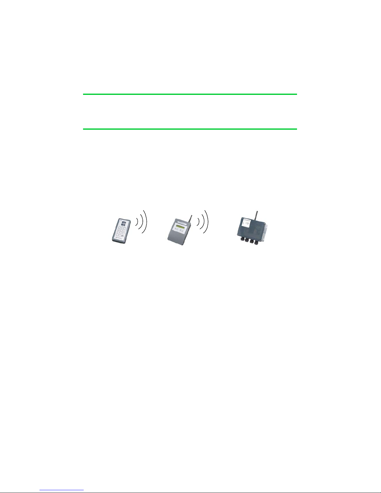
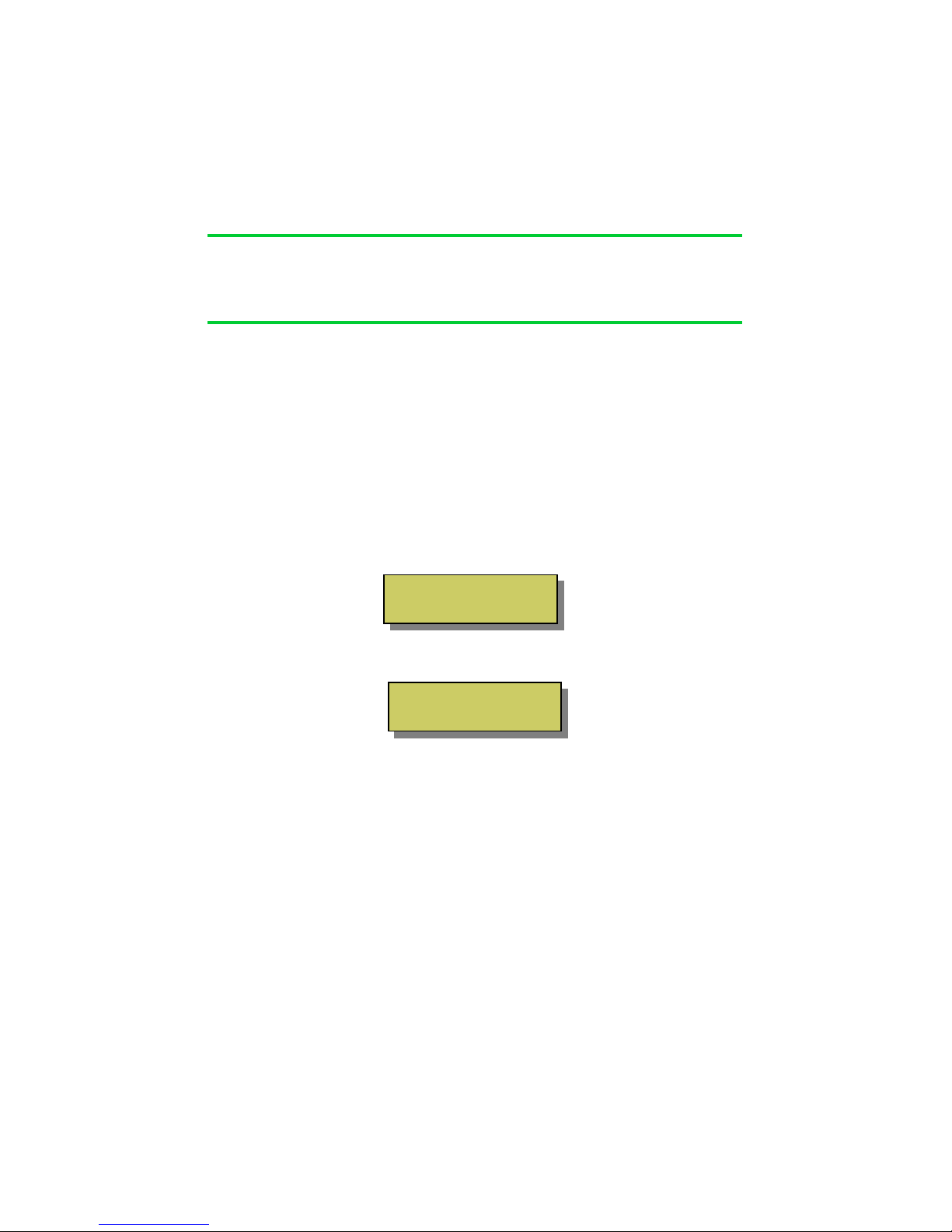
Locating the base-station in the best position is important and the diagram below
shows why. A key function of the base-station is to ‘echo’ commands received from
the remote control(s) to the garden. This creates a very reliable system because the
base-station and Lighting Control Modules don‘t move, which makes the signal-path
constant and therefore consistent, meaning it will always work!
Remote Base Lighting Control
control Station Module
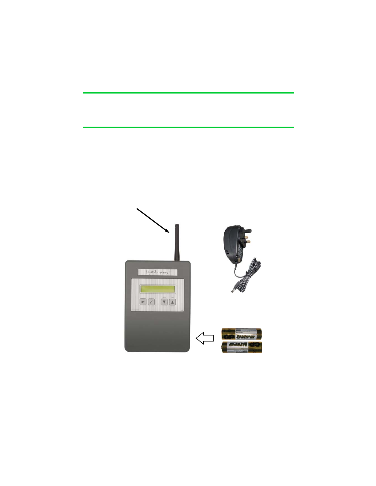
For the base-station’s signal to reach the outdoor ‘Lighting Control Modules’, it
should be located somewhere that gives good radio coverage of the garden. The
base-station is not water-proof and so must be fitted indoors, but try to fit it where it
has the best ‘radio-view’ to the garden i.e. with as few obstacles in the way as possi-
ble, such as buildings and walls.
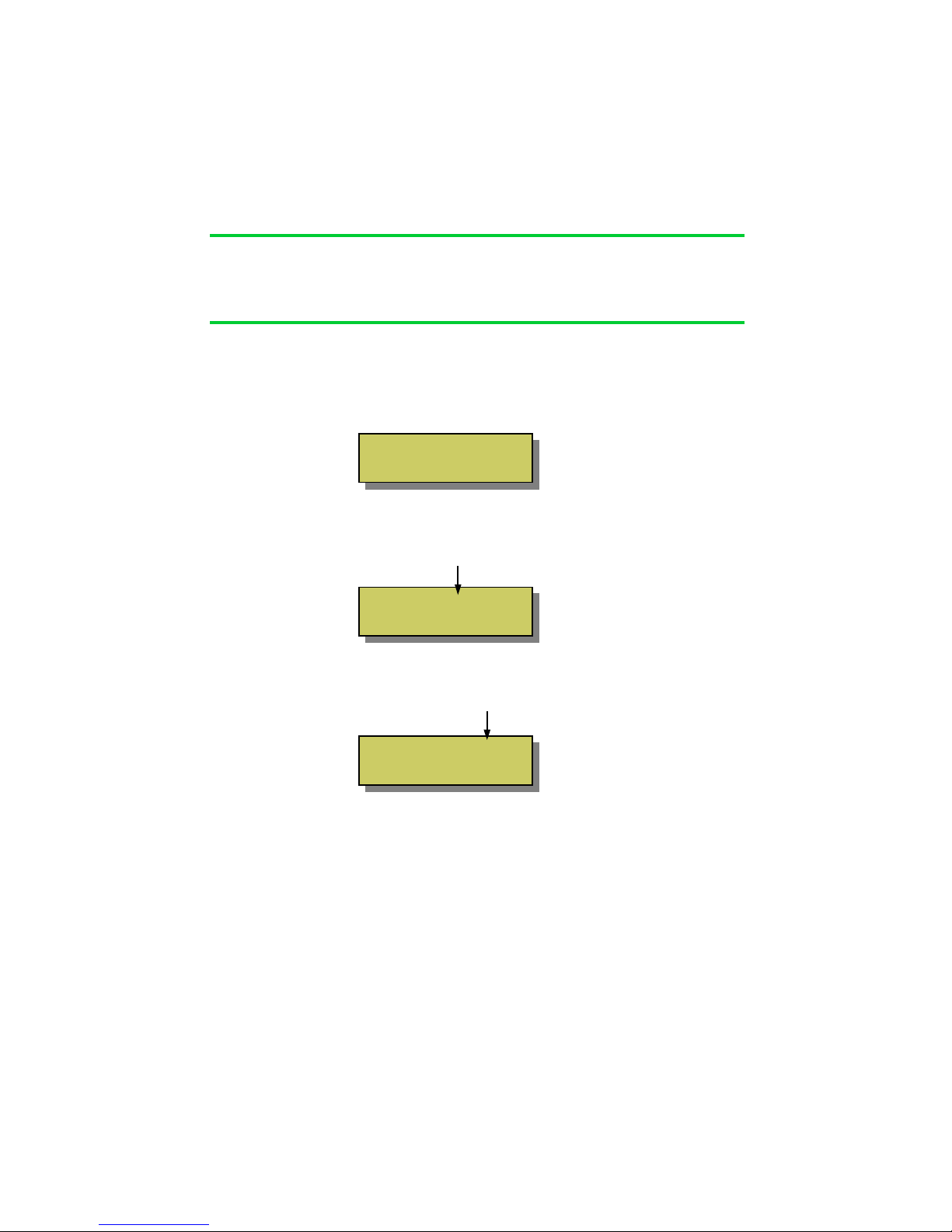
Radio signals do pass through most non-metallic materials but the thicker they are
the more signal is lost. As a rough guide, each standard cavity-wall will reduce the
range by 50% (1000M to 500M). Radio signals do not pass easily through metallic
obstacles such as reinforced concrete or garage doors, and significant range will be
lost.
The base-station does not need day-to-day attention, so it can be fitted in a discrete
location. An example is a loft-space, since the roof usually gives a good radio-view
of the front and back garden.
If ‘Repeater’ units are included in the installation, please pay special attention to the
radio link between the base-station and the repeaters, as detailed in the instructions
for these units.
Section 1
Installation
Location

Section 2
Initial Setup
Front Panel
9VDC Power
Interface Port
Serial interface
LCD Display
NAVIGATE
Navigates the menu
OK / STORE
Store settings
DOWN key
(All Area’s OFF)
UP key
(ALL Area’s ON)
5

Section 2
Initial Setup
Navigating The Menu
The base-station has many functions but all are easily configured from the simple key-
pad. The list below shows all the configurable options in the order in which they are
displayed;
1 Set Time / Date
2 Set Location
3 Set Dusk / Dawn
4 Set Timer 1
5 Set Timer 2
6 Set Timer 3
7 Set Timer 4
8 Set Timer 5
9 Set Timer 6
10 Set External Input
11 Set Light Show
12 Set System Code
13 Set Role
14 Set Protocol
15 WiFi Status
16 Configure WiFi
17 Quit no changes.
To enter the menu press the navigation key “” once. The display will change to show
The display shows menu line 1 from the list above, use the UP and DOWN keys to
move to other menu options and then press “9” to select. After 30 seconds of no
activity the display will return to the clock.
6
Press 9to
Set Time/Date

Section 2
Initial Setup
Setting the Time / Date
Navigate to the time/date menu by pressing the “” key once. The display will
change to show ...
Press the “9” key to enter the Time/Date menu. The display will change as shown
below. The ‘hours’ will be blinking and may be adjusted to the correct time with the
UP and DOWN keys
.
Once set, press the “” key once and then adjust the minutes to the correct time, as
show below.
Step through each setting using the “” key until the time and date are set, then
press the “9” key to exit the set-up and return to the main display.
The base-station will automatically keep track of summer and winter daylight saving
time. If fitted with good quality ‘AA’ batteries, the clock will be maintained during
power-cuts for several years (see page 3).
7
Press 9to
Set Time/Date
Time: 00:01
Thu 01 JAN 2010
Time: 16:01
Thu 01 JAN 2010

Dusk / Dawn Time & Location
The base-station includes an astronomical clock which calculates Dusk and Dawn
times throughout the year. This can be useful for setting timers; for example you may
like the lighting to switch on (as it gets dark) at dusk, and switch off again at 11pm.
In this case, the ‘on’ time will automatically adjust throughout the year to match
seasonal daylight hours.
Dusk and Dawn times vary slightly depending on your location. For example, sunset
(dusk), in the winter months, is a few minutes earlier in the north of the country than
in the South. Therefore the base-station can be tailored to a specific location to en-
sure the dusk and dawn times are calculated as accurately as possible.
By default, the base-station assumes its location is Birmingham, which will give
reasonably accurate results for the whole of the UK (+/-5 minutes).
However, if you wish to improve on this, then navigate to the “Location” menu and
select a town nearest to you.
Setting Location
Navigate to the ‘Location’ menu by pressing the “” key once then pressing the
DOWN key once. The display will change to show ...
Press the “9” key to enter the ‘Location’ menu. The display will change to show...
Navigate by pressing the “” key to
select and adjust the Region and town
nearest you. Press the “9” key when
done to store and exit the menu.
8
Section 2
Initial Setup
Reg England
Nr. Birmingham
Press 9to
Set Location

Section 2
Initial Setup
8
8
Setting Dusk / Dawn Time
Although the base-station calculates the precise dusk and dawn times for your location,
you may prefer your lighting to come on slightly before sunset (dusk) or slightly after.
Similarly, you may prefer the lights to go off just after sunrise (dawn) or just before.
You can easily modify the Dusk and Dawn times to suit your preference using the
Dusk/Dawn menu.
Navigate to the ‘Set Dusk/Dawn’ menu by pressing the “” key once then pressing
the DOWN key twice.. The display will change to show …
Press the “9” key to enter the ‘Dusk/Dawn’ menu. The display will change to show…
Use the UP / DOWN keys to modify the DAWN time.
Use the “” key to select the DUSK time and adjust in the same way.
Press the “9” key when done to store and exit the menu
9
DAWN: 07:59 +00min
DUSK: 16:21 +00min
Press 9to
Set Dusk / Dawn

The base-station contains 6 powerful and independent timers. Each timer may be
configured separately to control different aspects of your garden.
The timers can be used to control an individual ‘Area’ of your garden or the whole
garden together (ALL).
It’s also possible for several timers to control the same lighting ‘Area’. For example
Timer 1 can be set to switch all lights ON at Dusk and OFF at 11pm. Timer 2 can be
set to switch all lights ON (again) at 4am and OFF at Dawn.
Each timer can be configured in one of three modes;
‘Every Day’ - Will operate 7 days a week
‘Weekends’ - Will only operate on Saturday and Sunday
‘Week Days - Will only operate Monday – Friday
Using this feature, different lighting effects can be programmed for different times of
the week.
All 6 timers are set-up in the same way, so only Timer 1 is illustrated here.
Setting Timer 1 (to 6)
Navigate to the ‘Timer 1’ menu by pressing the “” key once and then press the
DOWN key 3 times. The display will change to show ...
10
Section 3
Timer Setup
Introduction
Press 9to
Set Timer 1

Setting Timer 1 (to 6) ...continued
Press the “9” key to enter the ‘Timer 1 (to 6)’ menu. The display will change to
show…
Use the UP / DOWN keys to choose the timer ‘type’ you prefer from the list on page
10 and then press the “9” key to see the Timer’s settings shown below;
ON TIME OFF TIME
‘AREA’ to be controlled
Use the UP/DOWN keys to adjust the ‘On-Time’ hours. You will notice as you
adjust past 00 the time changes to show ‘DUSK’. Using the Dusk setting will
automatically adjust the on-time each day to suit the calculated sunset time.
Next, use the navigation key “” to select the ‘Off-Time’ and set to your preference.
Again, you will notice as you adjust the hours past 00 the off-time changes to show
“DAWN”. Using the Dusk setting will automatically adjust the off-time each day to
suit the calculated sunrise time.
Lastly, use the navigation key “” to select the ‘Area’. The default is “ALL”, which
means the timer will control the whole garden together. You can use the UP /
DOWN keys to change this to a specific ‘Area’ from 1 to 9, which correspond to the
same area’s programmed on the remote control.
Press the “9” key when done to store and exit the menu.
11
Section 3
Timer Setup
Timer Type
Every Day
00:00 to 00:00
Area: All

Setting Timer 1 (to 6) ...continued
It is also possible to configure the timer for a specific length of time. For example,
to switch on at sunset (Dusk) for 3 hours. In this example, since the on-time changes
throughout the year, the off-time will track these changes ensuring the lights are
only on for 3 hours.
To use the timer in this way, simply navigate to the ‘to’ part of the display and use
the Up/Down keys to change it to ‘for’, as shown below
Next, use the navigation key “” to select the ‘on-hours’, which can be adjusted
using the Up / Down keys in 0.5hr steps from 0.5 to 6 hours.
Press the “9” key when done to store and exit the menu.
12
Section 3
Timer Setup
DUSK for 3hrs
Area: All

Section 4
Colour Light Show
Colour Light Show
The base-station is the control hub for Light Symphony’s Colour Light Show.
The Light Show is for controlling colour RGB (red/green/blue) lights and can
wirelessly synchronise the speed, timing and colour of any number of LEDs. To set-
up a ‘Light Show’ the RGB controller(s) must be included in a lighting Area (zone).
For example: to include a RGB lighting controller in say ‘Area 8’, simply double-tap
the RGB controller to switch it on, then press the ‘Area 8’ key on the remote control
to store it. The RGB controller will beep and, if the LEDs were ON at the time, they
will now be stored in that Area. (to remove a controller from an Area, double-tap
until the LEDs are off then press the Area key).
Next, set the Base-Station’s Light Show to the same Area. e.g. no. 8 (see page 14).
The Light Show will run whenever Area 8 (or your chosen Area) is switched on. The
light show will also be started by the remote control’s ‘Garden On’ button or any
timer set to control the same Area.
The light show will gently fade between the range of colours selected, including ALL
(16 key colours), WARM (red, orange, yellow etc), COOL (blue, violet, white etc),
RGB (red, green and blue only) or PASTEL.
The ‘speed’ of the light show can be controlled from 3 to 60 second intervals. For
example, if the show is set to step every 60 seconds, the colour will change very
gently over a 60 second period. Like the slow moving minute-hand on a clock, this is
barely perceivable and therefore creates a very subtle and pleasing effect.
Any non-RGB lighting controllers included in the Light Show Area will not be
effected by the show but will still switch on and off with the Area.
13

Colour Light Show set up
To configure the Light Show to your preference, navigate to the ‘Set Light Show’
menu by pressing the “” key then pressing the DOWN key ten times. The display
will change to show;
Press the “9” key to enter the Light Show set-up;
Use the Up/Down keys to select the Area to be controlled by the Light Show. Next
press the “9”, the display will briefly show “STORED” and then display;
Use the “” navigation key to select the time and colour options and use the Up/
Down keys to adjust them.
Select between time intervals of 3, 5,10, 20, 30 and 60 seconds.
Select between; None (white light), All (any colour), Primes (primary colours only),
Warm (reds, oranges etc), Cool (blues, violets etc) or Pastel colours.
Press “9” to STORE the settings and exit the menu. Note; these settings can be
adjusted via the smart phone app but the changes will not be stored.
14
Section 4
Light Show
Press 9to
Set Light Show
Speed : 5 sec
Colour : None
Light Show
Area : 8

Section 5
Interfacing – Advanced Setup
Introduction
The base-station provides several interface options allowing connection to third party
equipment.
1. Digital Trigger Input
2. Serial Port*
3. WiFi Network*
*NOTE
The serial port and Wifi interfaces are only
available on the WiFi version of the base-station
Digital Trigger Input
The base-station includes a low-voltage trigger input which may be used to trigger
the lighting. It can be useful for interfacing to an external sensor such as a light
beam across a drive-way , PIR motion sensor or even an alarm panel so the lighting
is triggered with the alarm.
The trigger input is rated maximum 5Volts, so a relay is usually required as shown
below;
15
RELAY
COIL
5V TRIGGER
INPUT
5V SUPPLY
Pin 8 = 0V
TRIGGER
VOLTAGE
Base-Station
Interface
8 7 6
5 4 3
2 1

Digital Trigger Input
The digital input may be configured in a number of modes;
1On / Off
2Trigger
3If Timer 1-5
4If Dusk
On / Off Mode
In this mode, the lighting will switched ON when the trigger input is activated
and switched OFF when the trigger input is de-activated. This allows interfacing
to a simple, external on/off type switch.
To configure the external input in on/off mode configure the menu like this;
16
Section 5
Interfacing – Advanced Setup
12
345
678
Base-Station
Interface
On / Off Switch
Ext : On / Off
Area: All
Press 9to
Set Ext Input

Digital Trigger Input ...continued
Trigger Mode
In trigger mode, the lighting is switched ON for a pre-set time when the trigger
input is activated. This allows interfacing to a sensor or bell-push type switch, where the
lighting must be triggered for a pre-set time and then automatically switched off again.
To configure the input to respond to a trigger, set the menu like this;
‘If Timer’ Mode
In ‘If Timer’ mode, the lighting will over-ride the setting of a Timer, but only if the
timer is active. For example, if Timer 1 is set to switch on Area 1 from Dusk to 11pm,
the digital input will be ignored outside these times.
This feature can be useful in a gate or drive-way application, where the lights are timed
to be on but kept at a low level (e.g. Area 1’s setting). When triggered by a car, the
lights can fade to full brightness (e.g. Area 2’s setting) for a pre-set time. At the end of
the triggered time interval, the lights will not switch off, but revert back to the Timer’s
setting (Area 1’s setting).
To configure the input to respond to a trigger with a Timer, set the menu like this;
‘If Dusk’ Mode – Works as ‘Trigger’ mode but only active between Dusk & Dawn
17
Section 5
Interfacing – Advanced Setup
Ext : Trigger
Area: All >3min
Press 9to
Set Ext Input
Ext : If Timer 1
Area: 2 >10min
Press 9to
Set Ext Input

Serial Port
The serial port can support a number of different protocols to simplify interfacing to
third party equipment.
The port is bi-directional for handshaking purposes, but only allows control ‘input‘,
i.e. Light Symphony can not be used to transmit its status back to a host controller.
The following RS232 protocols are supported at this time;
1Ascii Baud rate; 300, 1200, 4800, 9600 19200
2Lutron Baud rate; 300, 1200, 4800, 9600 19200
In both cases the format is 8 bits, with 1 start, 1 stop bit (no parity)
Commands received over the serial port over-ride any user or internal (timed)
events.
Serial Pin-Out
To configure the serial port select the protocol menu shown below;
18
Section 5
Interfacing – Advanced Setup
12
345
678
Base-Station
Interface
RS232 RS485/422
Pin 3 – Tx Pin 3 – Tx-
Pin 5 – Rx Pin 4 – Tx+
Pin 7 – Gnd Pin 5 – Rx-
Pin 6 – Rx+
Protocol Speed
Ascii 9600
Press 9to
Setup Protocol

Serial Port … continued
ASCII Interface
The port expects simple lower-case ASCII messages in the format below;
Lutron® Interface
The serial port can be configured to support Lutron’s ® GrafikEye serial protocol.
To select the Lutron protocol, configure the protocol screen like this;
19
Section 5
Interfacing – Advanced Setup
Message Action
all_on Switch ON all areas
all_off Switch OFF all areas
area_on x Switch ON area ‘x’, where x = “0” to “9”
area_off x Switch OFF area ‘x’, where x = “0” to “9”
start-show Start light-show running
stop_show STOP light show
inten_x Set intensity of last selected area to ‘x’
where x = “0” to “9”
Protocol Speed
Lutron 9600
Press 9to
Setup Protocol
This manual suits for next models
1
Table of contents
Popular Accessories manuals by other brands

Carefree
Carefree PARAMOUNT owner's manual

DELTA PLUS
DELTA PLUS CONICFIR010 quick start guide

eLICHENS
eLICHENS AURA CO2 quick start guide

Lennox EMEA
Lennox EMEA Euromon 100 Series Installation, user and maintenance manual

quadient
quadient IS-240 Replacement guide

Hafele
Hafele Pop-up Worktop Socket Assembly guide