LIGHTBOARD DEPOT LBD4832-DT-A-1 User manual

ASSEMBLY INSTRUCTIONS
1 | P a g e
Need more help? Contact us any time at:
info@lightboarddepot.com
[B]
HOW TO ATTACH FEET TO SCREEN AND HOW TO ASSEMBLE YOUR SIT-STAND TABLE-TOP
PART 1 - ASSEMBLY OF YOUR LIGHTBOARD SCREEN
Information for the following kits is included in this document:
•BD4832-DT-A-1
•BD4832-DT-G-1
•BD4832-SS-A-1
•BD4832-SS-G-1
A) STEP 1 UNB OXING YOUR KIT
When you receive your ightBoard kit, you will have TWO boxes to unpack:
i. ightBoard Screen
ii. Accessories & Hardware Box
If you Ordered a Sit-Stand kit, you will also see a box for:
iii. The Sit-Stand mechanism
iv. The Tabletop
To assembly the ightBoard, you will need to locate the Metal hardware and Allen wrench, within the Accessories
Box as follows:
•8x Screws
•6x Threaded Tabs
•1x Allen Wrench
•2x Partially Assemble LightBoard Feet with Attached Angle bracket
•2x Flat Metal Braces
•6x Rubber Pads
(not shown)
•If you have ordered a Sit-Stand Kit – You will also need a #2 Philips (Star) Screwdriver
(NOT INCLUDED)

ASSEMBLY INSTRUCTIONS
2 | P a g e
Need more help? Contact us any time at:
info@lightboarddepot.com
[B]
B) STEP 2 GET YOUR SCREEN SAFELY POSITIONE D FOR ASSEMBLY
Before you Start, find an elevated, clean, and flat space to rest your unpacked ightBoard Screen as follows:
Put padding & protection, such as thin foam or cushions, down as needed to protect your screen from damage
during the assembly process
C) STEP 3 INSERT THREADED TABS INTO SCREEN LEGS
Before you can attach the feet, you must insert a total of THREE threaded tabs PER SIDE into the left and right
channels of the ightBoard Screen’s legs.
The First One is inserted facing “outward” as follows:
The Second TWO are inserted facing “up”, as shown.

ASSEMBLY INSTRUCTIONS
3 | P a g e
Need more help? Contact us any time at:
info@lightboarddepot.com
[B]
D) STEP 4 ASSEMBLE THE FEET ONTO THE SCREEN
Now that the sliding threaded tabs are in place, you may now attach the first Foot using two of the provided
screws as below, mounting to the two tabs that were inserted together in STEP 3:
Repeat this step for the SECOND foot, and ensure that the Angled bracket is facing “inwards” towards the Screen.
Tighten the screws.
First Foot Attachment Second Foot Attachment
If you were provided with rubber pads for your Kit (such as in Desktop kits), you may place them on the
bottom of the feet at this time. THREE Pads should be placed on each foot, one on each end, and one
directly underneath where the Screen and Foot join perpendicular.

ASSEMBLY INSTRUCTIONS
4 | P a g e
Need more help? Contact us any time at:
info@lightboarddepot.com
[B]
E) STEP 5 TURN THE DISPLAY UPRIGHT
Ask someone for assistance and together, turn the ightBoard upright, now with feet secured tightly.
F) STEP 6 ATTACH METAL BRACES BETWEEN THE FEET AND THE SCREEN
Now that the ightBoard is standing, you can attach the metal braces to secure the ightBoard for use.
NOTE: You will have to slide the Threaded Tabs, which should already be inside the Screen rail (C) STEP 3, as well
as the Foot rail, into position such that the Brace will be mounted at approximately 45 degrees as shown below:
This is best done starting with the TOP screw (on the Screen rail):
[Make special note of the hole orientation shown]
1. 2.
Followed by the BOTTOM screw, attached to the foot.

ASSEMBLY INSTRUCTIONS
5 | P a g e
Need more help? Contact us any time at:
info@lightboarddepot.com
[B]
Repeat this step for the other side of the ightBoard, such that it resembles the photo below.
Make sure to tighten all of the screws.
G) STEP 7 PLUGGING IT IN
Your ightBoard is now fully assembled mechanically and ready to go!
The AST STEP is to attach your Remote or Manual control switch for the illumination lamp inside of the screen and
plug it into the wall to ensure it is running properly:
•Attach your control switch to the barrel connector coming from the Screen frame:
•Then connect the control switch to your AC wall adapter.

ASSEMBLY INSTRUCTIONS
6 | P a g e
Need more help? Contact us any time at:
info@lightboarddepot.com
[B]
H) STEP 8 ENJOY!
Your LightBoard is now ready for your studio!
Please see document
C. Basic Setup Instructions
for further details on setting up your studio
environment with the other components in your kit.
Don’t forget to give your ightBoard a thorough cleaning before use!
See
D. Product Care & Maintenance
for details & best practices when cleaning & handling your
ightBoard.

ASSEMBLY INSTRUCTIONS
7 | P a g e
Need more help? Contact us any time at:
info@lightboarddepot.com
[B]
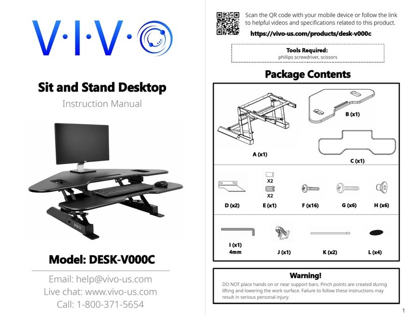
PART 2 - ASSEMBLY OF YOUR SIT-STAND TABLE
If you’ve purchased the Sit-Stand Kit, please refer to the below instruction as to how to
securely attach your tabletop to the Sit-Stand Mechanism provided with the kit
Tools you will need before starting:
•#2 Philips-head (Star) Screw driver
•(optional) C
ordless-drill with a #2 Phillips bit AND a 1/16-in drill bit for pilot holes
A) STEP 1 SIT-STAND MECHANISM ASSEMBLY
Open your provided Sit-Stand mechanism box and find the provided assembly tools, hardware and assembly
instruction pamphlet. Please follow the instructions provided in the kit to assemble the mechanism.
B) STEP 2 ATTACHING THE TABLETOP
To attach the provided tabletop, first check to see if your provided tabletop has pre-drilled holes in it.
•If your tabletop has pre-drilled holes, place it face-down onto a clean, flat surface, and rest your sit-stand
mechanism on top (the feet should be pointing upward). You may use the existing holes as a guide when
spreading the sit-stand legs apart. Simply follow the instructions provided with the sit-stand mechanism
and use the provided wood screws to screw the mechanism onto the tabletop as directed.
• If your tabletop does NOT have pre-drilled holes, place it face-down onto a clean, flat surface, and rest
your sit-stand mechanism on top (the feet should be pointing upward). You will then need to center and
align the legs on your table top and spread the legs to a spacing of at least 42-in, wider is preferred for
stability, tabletop permitting. Once the legs are centered and spread to an appropriate position, there are
two options:
i) Mark the holes as directed in the instructions for the sit-stand, and use a drill with a 1/16-in drill-bit
to drill pilot holes for your screws. This will ensure straightness and best security of your desk
ii) If you do not have access to a drill, the wood screws CAN be screwed in directly to the tabletop
securely using a screwdriver, but the table is less likely to remain centered and there is risk it will
not stay level depending on how flush/straight the screws sit into the tabletop when done by hand
without pilot holes.
C) STEP 3 FIN ISHING THE SETUP
Once the tabletop is secured, ask for assistance and flip the table upright. Ensure the tabletop is stable, and test
the controls (either manual or electric) to ensure all mechanisms are functioning properly before putting your
ightBoard onto the desk.
Once the above is confirmed, you may now place your ightBoard safely onto the sit-stand desk and start your first
session!
This manual suits for next models
3
Table of contents