3
1. Montage der MediaBox 04423 und 04424
Assembly of MediaBox 04423 and 04424
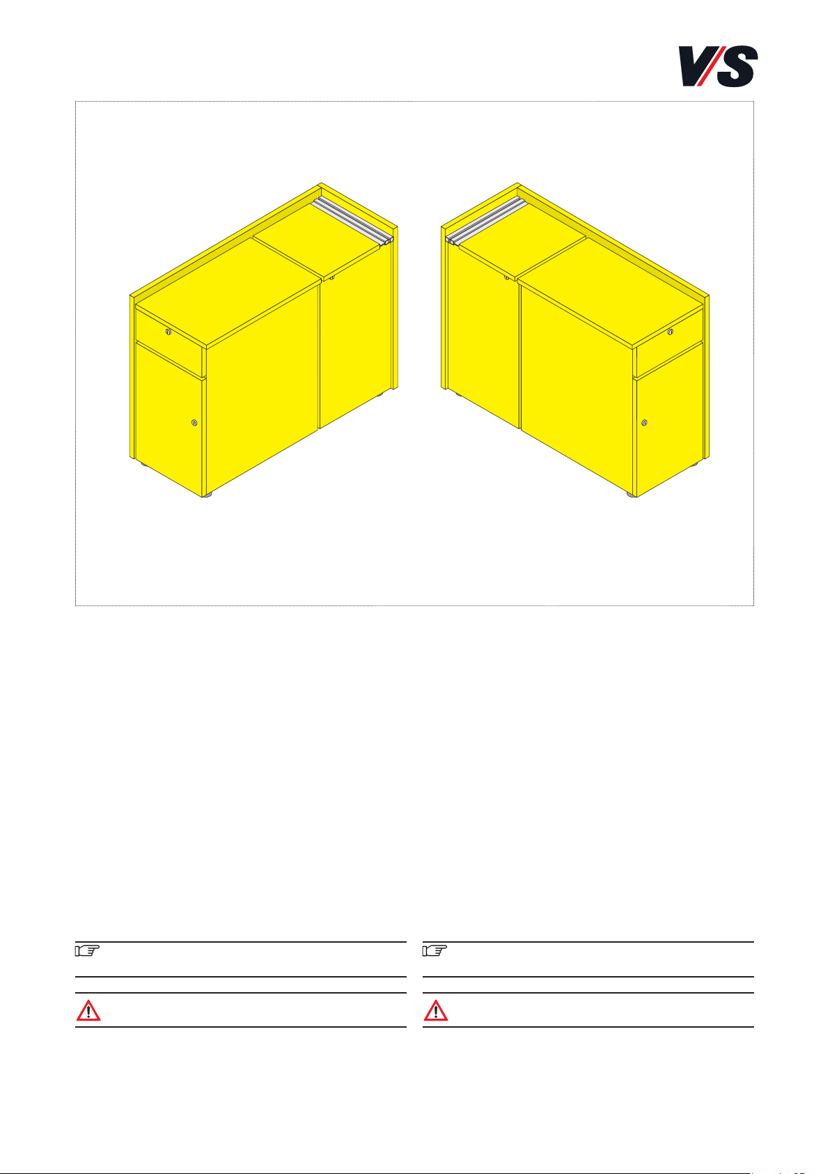
Richten Sie die MediaBox (1) am gewünschten Ort korrekt
aus. Die Zuführung von Strom (2) und Ethernet erfolgt
von unten durch die dafür vorgesehene Öffnung (4) oder
seitlich bei Varianten mit seitlichem Kabelauslass (3).
Stellen Sie sicher, dass die Leitungen vor dem Aufstellen
der MediaBox entsprechend sicher verlegt sind.
Position the MediaBox correctly at the required location.
Power (2) and Ethernet are supplied from below through
the hole (4) provided for this purpose or from the side
in the case of variants with a side cable outlet (3). Be-
fore installing the MediaBox, make sure that the cables
are routed securely.
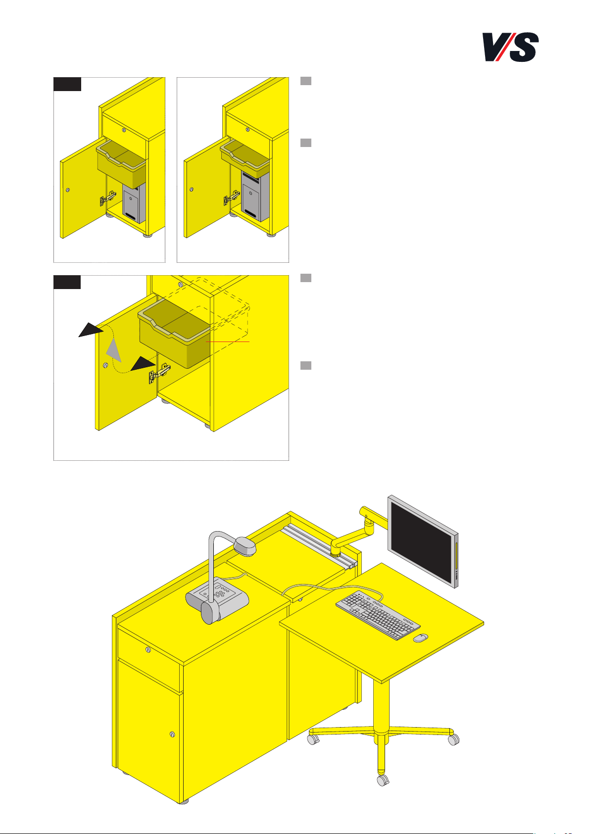
Nur Modell ohne Ausgleichsgewichten: Verankern Sie
die MediaBox (1) durch zwei diagonal gegenüber liegenden
Befestigungsbohrungen (5) mit geeigneten Dübeln (6) am
Boden. Verwenden Sie hierzu die Schraube (7) sowie die
Beilagscheibe (8) aus dem Beipack. Decken Sie anschließend
alle vier Befestigunsbohrungen mit Abdeckkappen (9) ab.
Wichtig! Die MediaBox ohne Ausgleichsgewichte muss
immer am Boden befestigt werden.
Only for model without balancing weights: Using suit-
able dowels (6), anchor the MediaBox (1) to the floor
via two diagonally opposed fixing holes (5). To do this,
use the screw (7) and washer (8) from the accessories
pack. Next, place covers (9) on all four fixing holes.
Important! The MediaBox without balancing weights
must always be fixed to the floor.
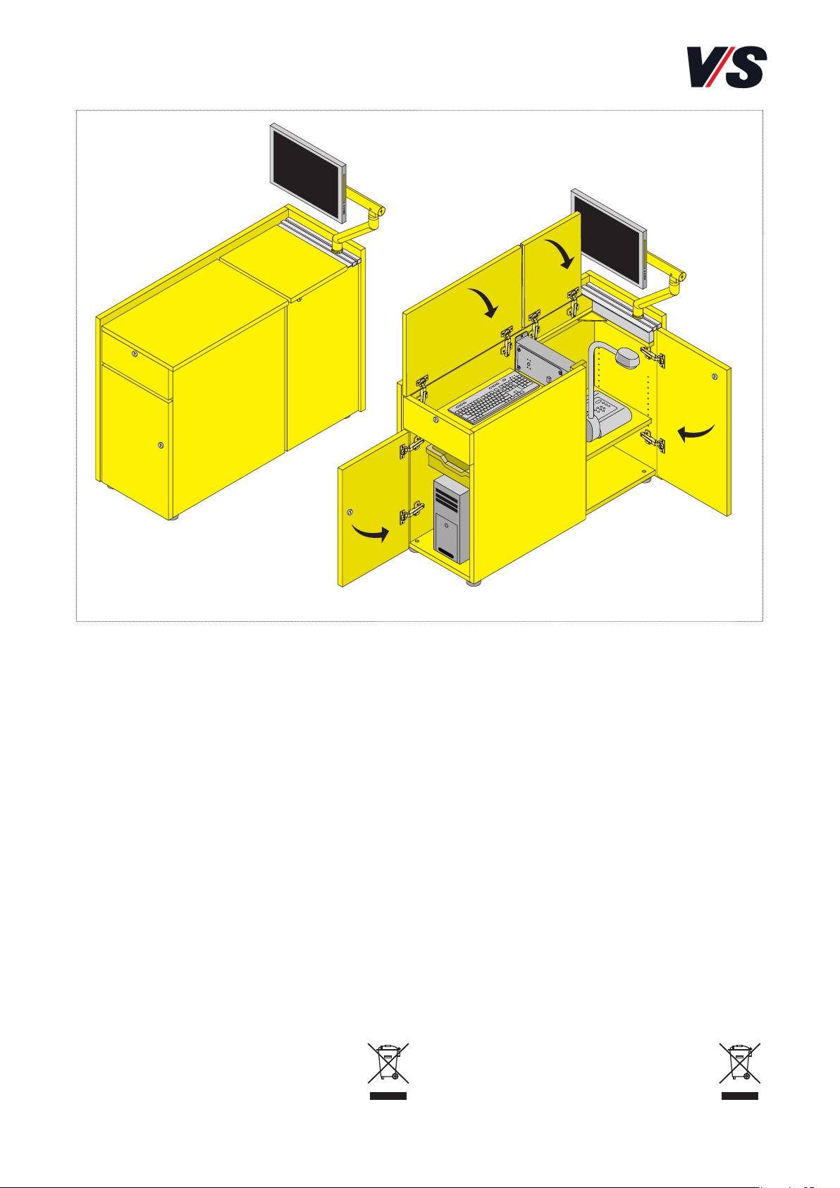
Modell mit Ausgleichsgewichten: Die Ausgleichs-
gewichte im Boden der MediaBox machen eine Ver-
ankerung im Untergrund unnötig. Die MediaBox verfügt
über vier Gleiter (10), welche mit einem Innensechskant
Schlüssel in der Höhe verstellt werden können, um Bode-
nunebenheiten auszugleichen.
Sollen Kabel durch den Boden geführt werden, müssen
die Gleiter entsprechend weiter ausgedreht werden.
Model with balancing weights: The balancing weights
in the base of the MediaBox mean that it is not neces-
sary to anchor it to the supporting surface. The Media-
Box has four glide elements (10) whose height can be
adjusted using an Allen key in order to compensate for
any unevenness in the floor.
If cables are to be routed through the base then the
glide elements must be extended further as required.
DE
EN
EN
DE
DE
EN
1.1
(1)
(2)
(3)
(4)
(10)
(1)
(6)
(5)
(5)
1.2
1.3
(9)
(7)
(8)