manuals.online logo
Brands
  1. Home
  2. •
  3. Brands
  4. •
  5. Lighting Science
  6. •
  7. Accessories
  8. •
  9. Lighting Science Healthe Cleanse Portal User manual

Lighting Science Healthe Cleanse Portal User manual

Popular Accessories manuals by other brands

Quincy lab 140AE-1 operating manual

Quincy lab

Quincy lab 140AE-1 operating manual

HomePro ZIR000 user manual

HomePro

HomePro ZIR000 user manual

DOL 20SCR Technical user guide

DOL

DOL 20SCR Technical user guide

RAB Smart Task installation manual

RAB

RAB Smart Task installation manual

Kemppi KMS 300 quick guide

Kemppi

Kemppi KMS 300 quick guide

Stearns 57,500 Series Installation and service instructions

Stearns

Stearns 57,500 Series Installation and service instructions

iGuzzini TWILIGHT COPENAGHEN manual

iGuzzini

iGuzzini TWILIGHT COPENAGHEN manual

Adelaide Annexe & Canvas Avan Deluxe installation guide

Adelaide Annexe & Canvas

Adelaide Annexe & Canvas Avan Deluxe installation guide

OHAUS 5000 instruction manual

OHAUS

OHAUS 5000 instruction manual

HOME8 WLS1300 quick start guide

HOME8

HOME8 WLS1300 quick start guide

MAXBOTIX MaxSonar quick start guide

MAXBOTIX

MAXBOTIX MaxSonar quick start guide

ioSmart iSmart56 Installation and user guide

ioSmart

ioSmart iSmart56 Installation and user guide

Focusrite Scarlett 18i8 user guide

Focusrite

Focusrite Scarlett 18i8 user guide

Velleman ED38105 user manual

Velleman

Velleman ED38105 user manual

JumpSport SkyBounce user manual

JumpSport

JumpSport SkyBounce user manual

Prima-Temp PRIYA Instructions for use

Prima-Temp

Prima-Temp PRIYA Instructions for use

Tefcold BC85I-BC85I W user manual

Tefcold

Tefcold BC85I-BC85I W user manual

Vaisala WMS302 user guide

Vaisala

Vaisala WMS302 user guide

manuals.online logo
manuals.online logoBrands
  • About & Mission
  • Contact us
  • Privacy Policy
  • Terms and Conditions

Copyright 2025 Manuals.Online. All Rights Reserved.

Cleanse®Portal
Installation Manual
HEALTHE BY LIGHTING SCIENCE |801 N ATLANTIC AVE, COCOA BEACH, FL 32931 |877.999.5742 |HEALTHELIGHTING.COM 1
PACKING LIST:
• Side Frame Assembly x 2
• Top Frame Assembly x 1
• Corner Motion Control Assembly x 2
• #6-32 x ½” Flat Head Screw x 8
• ¼”-20 x ¾” Security Head Screw x 6
TOOLS NEEDED:
• T27 Security Torx wrench
• #2 Philips head screw driver
Please review all parts and hardware before disposing of any
packaging. Please use recommended tools for assembly.
IMPORTANT SAFETY INSTRUCTIONS
This product has 3-prong plug that allows a grounding wire to be
connected from the electrical circuit to the product. The grounding wire
is connected to the third prong of the plug. When the 3-prong plug is
plugged into the receptacle, the grounding wire is connected to the prong
and provides a continuous grounding path from the product back to the
breaker box. This grounding path serves as primary safety means if there
is a short circuit or other damage to the electrical circuit or product.
CAUTION
TO PREVENT ELECTRICAL SHOCK, MATCH 3-Prong Plug to 3-Prong
Receptacle, FULLY INSERT.
Top Frame Assembly
Corner Motion
Control Assembly
Side Frame
Assembly
Cleanse®Portal
Installation Manual
HEALTHE BY LIGHTING SCIENCE |801 N ATLANTIC AVE, COCOA BEACH, FL 32931 |877.999.5742 |HEALTHELIGHTING.COM 2
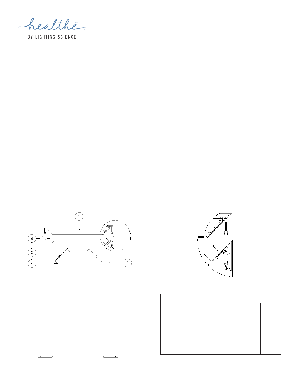
DETAIL A
A
INSTALLATION - OVERALL ASSEMBLY
1. At or near the desired installation location, unpack all components and verify the contents against the packing list.
2. Set the two Side Frame Assembly (item 2) at 35.5” distance apart (as shown in Fig 1).
3. Set the Top Assembly (item 1) on the top of the two Side Frame Assembly (as shown in Fig 1).
4. Connect all electrical connections by attaching all corresponding quick connectors between Top Frame Assembly and the two Side Frame Assembly
(see Fig 1 Detail A, Fig 2 Detail B)
5. Fasten Top Frame Assembly and Side Frame Assemblies with ¼”-20 x ¾” Security Head Screws (Item 5) as shown in Fig 1.
6. Connect each of the Corner Motion Control Assembly each side of the Frame using the corresponding connector (see Fig 3 Detail C).*
7. Fasten the two Corner Motion Control Assembly (Item 3) with #6-32 x ½” Flat Head Screws (Item 4) as shown in Fig 1.
8. Plug in the 3-prong plug into the power outlet.
9. Locate the two (2) Power/Control switches on Side Frame Assembly. Switch 1 is located above the power cord and Switch 2 is located below the power
cord. Adjust Switch 1 to desired control operation to activate the Portal as shown in Fig 3.
• Switch 1
⸰ Top Position: Constant On
⸰ Middle Position: OFF
⸰ Bottom: Motion Controlled (Default)
10. For Switch 2 located below the power cable, please ensure the switch is ALWAYS ON THE BOTTOM position at all times. Any other position will cause
the Portal to not function properly.
11. While Portal is designed to be free-standing, anchor holes are available on the base of each Side Frame Assembly and can be used to secure the Portal
to the ground by using 1/4" fasteners.
* There is no polarity requirement of Corner Motion Control Assembly installation.
ITEM LIST
Item Number Part Description Quantity
1 Top Frame Assembly 1
2 Side Frame Assembly 2
3 Corner Motion Control Assembly 2
4 # 6-32 x 1/2" Flat Head Screw 8
51/4"-20 x 3/4" Security Head Screw 6
Fig. 1
• Switch 2
⸰ Bottom: On (Default)
Cleanse®Portal
Installation Manual
HEALTHE BY LIGHTING SCIENCE |801 N ATLANTIC AVE, COCOA BEACH, FL 32931 |877.999.5742 |HEALTHELIGHTING.COM 3
ELECTRICAL CONNECTION – ADDITIONAL DETAILS
Fig. 2
ADDITIONAL DIAGRAMS
Fig. 3 Fig. 4
DETAIL B
SCALE 1 : 8
B
©2020 Healthe Inc. All Rights Reserved. Specications subject to change without notice. Cleanse_Portal_InstallationManual_052920
On (Default)
DETAIL C
SWITCH 1
SWITCH 2
Constant On
OFF
Motion Controlled
(Default)