Stübbe PTM C2 Series Installation instructions
Sensor
pressure
Original operating manual Series
PTM C2
Version BA-2016.11.24 EN
Print-No. 300 196
TR MA DE Rev002
ASV Stübbe GmbH & Co. KG
Hollwieser Strasse 5
32602 Vlotho
Germany
Phone: +49 (0)5733-799-0
Fax: +49 (0)5733-799-5000
Email: contact@asv-stuebbe.de
Internet: www.asv-stuebbe.com
We reserve the right to make technical changes.
Read carefully before use.
Save for future use.

Table of contents
Table of contents
1 About this document ............................... 3
1.1 Target groups ................................. 3
1.2 Other applicable documents ................ 3
1.3 Warnings and symbols ....................... 3
2 General safety instructions ....................... 4
2.1 Intended use .................................. 4
2.2 General safety instructions .................. 4
2.2.1 Obligations of the operating company ...... 4
2.2.2 Obligations of personnel ..................... 4
2.3 Specific hazards .............................. 4
2.3.1 Hazardous media ............................ 4
3 Layout and Function ............................... 5
3.1 Type plate ..................................... 5
3.2 Description .................................... 5
3.3 Layout ......................................... 5
3.3.1 Layout ......................................... 5
4 Transport, Storage and Disposal ................. 5
4.1 Unpacking and inspection on delivery ...... 5
4.2 Transportation ................................ 5
4.3 Storage ....................................... 5
4.4 Disposal ....................................... 6
5 Installation and connection ....................... 6
5.1 Check operating conditions ................. 6
5.2 Installing device in the process
pipework ...................................... 6
5.3 Performing the hydrostatic test .............. 6
5.4 Electrical connection of device .............. 6
6Operation ............................................ 7
6.1 Initial start-up ................................. 7
7 Maintenance ......................................... 7
7.1 Servicing ...................................... 7
7.2 Maintenance .................................. 7
7.2.1 Removing the device ........................ 7
7.2.2 Replacement parts and return .............. 7
8 Troubleshooting .................................... 8
9 Appendix ............................................. 8
9.1 Technical specifications ...................... 8
9.2 Dimensions ................................... 8
9.3 Plug assignment ............................. 8
List of figures
Fig. 1 Type plate ..................................... 5
Fig. 2 Layout ......................................... 5
Fig. 3 Connection diagram ......................... 8
List of tables
Tab. 1 Other application documents, purpose and
where found .................................. 3
Tab. 2 Warnings and symbols ....................... 3
Tab. 3 Servicing activities ........................... 7
Tab. 4 Troubleshooting .............................. 8
2 PTM C2 BA-2016.11.24 EN 300 196
About this document
1 About this document
This manual
• is part of the equipment
• applies to all series referred to
• describes safe and proper operation during all operating
phases
1.1 Target groups
Operating company
• Responsibilities:
– Always keep this manual accessible where the device
is used on the system.
– Ensure that employees read and observe this docu-
ment, particularly the safety instructions and warnings,
and the documents which also apply.
– Observe any additional country-specific rules and reg-
ulations that relate to the system.
Qualified personnel, fitter
• Mechanics qualification:
– Qualified employees with additional training for fitting
the respective pipework.
• Electrical qualification:
– Qualified electrician
• Transport qualification:
– Qualified transport specialist
• Responsibility:
– Read, observe and follow this manual and the other
applicable documents, especially all safety instructions
and warnings.
1.2 Other applicable documents
To download:
Resistance Guide
Chemical resistance of the materials
used
www.asv-stuebbe.de/pdf_resistance/300051.pdf
To download:
Data sheet
Technical data, operating conditions
www.asv-stuebbe.de/pdf_datasheets/300190.pdf
To download:
CE declaration of conformity
Conformity with standards
www.asv-stuebbe.de/pdf_DOC/300298.pdf
Tab. 1 Other application documents, purpose
and where found
1.3 Warnings and symbols
Symbol Meaning
• Immediate acute risk
• Death, serious bodily harm
• Potentially acute risk
• Death, serious bodily harm
• Potentially hazardous situation
• Minor injury
• Potentially hazardous situation
• Material damage
Safety warning sign
Take note of all information
highlighted by the safety warning
sign and follow the instructions to
avoid injury or death.
Instruction
1. , 2. , … Multiple-step instructions
Precondition
→Cross reference
Information, notes
Tab. 2 Warnings and symbols
300 196 BA-2016.11.24 EN PTM C2 3

General safety instructions
2 General safety instructions
The manufacturer accepts no liability for damages caused
by disregarding any of the documentation.
2.1 Intended use
Thedeviceallowspressureinaliquidmediumtobemeasured.
• Device must only be used for measuring pressure in liquid
media.
• Only use the device with suitable media
(→resistance lists).
• Adhere to the operating limits (→9.1 Technical specifica-
tions, Page 8).
2.2 General safety instructions
Observe the following regulations before carrying out any
work.
2.2.1 Obligations of the operating company
Safety-conscious operation
• Only operate the device if it is in perfect technical condition
and only use it as intended, staying aware of safety and
risks, and in adherence to the instructions in this manual.
• Ensure that the following safety aspects are observed and
monitored:
– Intended use
– Statutory or other safety and accident-prevention reg-
ulations
– Safety regulations governing the handling of haz-
ardous substances
– Applicable standards and guidelines in the country
where the pump is operated
• Make personal protective equipment available.
Qualified personnel
• Make sure all personnel tasked with work on the device
have read and understood this manual and all other appli-
cable documents, especially the safety, maintenance and
repair information, before they start any work.
• Organize responsibilities, areas of competence and the
supervision of personnel.
• The following work should be carried out by specialist tech-
nicians only:
– Installation, repair and maintenance work
– Work on the electrical system
• Make sure that trainee personnel only work on the device
under supervision of specialist technicians.
2.2.2 Obligations of personnel
Only complete work on the device if the following requirements
are met:
• System is empty
• System has been flushed
• System is depressurized
• System has cooled down
• System is secured against being switched back on again
• Do not make any modifications to the device.
2.3 Specific hazards
2.3.1 Hazardous media
• When handling hazardous media, observe the safety reg-
ulations for the handling of hazardous substances.
• Use personal protective equipment for all work on the
device.
• Collect leaking pumped liquid and residues in a safe man-
ner and dispose of in accordance with environmental reg-
ulations.
4 PTM C2 BA-2016.11.24 EN 300 196
Transport, Storage and Disposal
3 Layout and Function
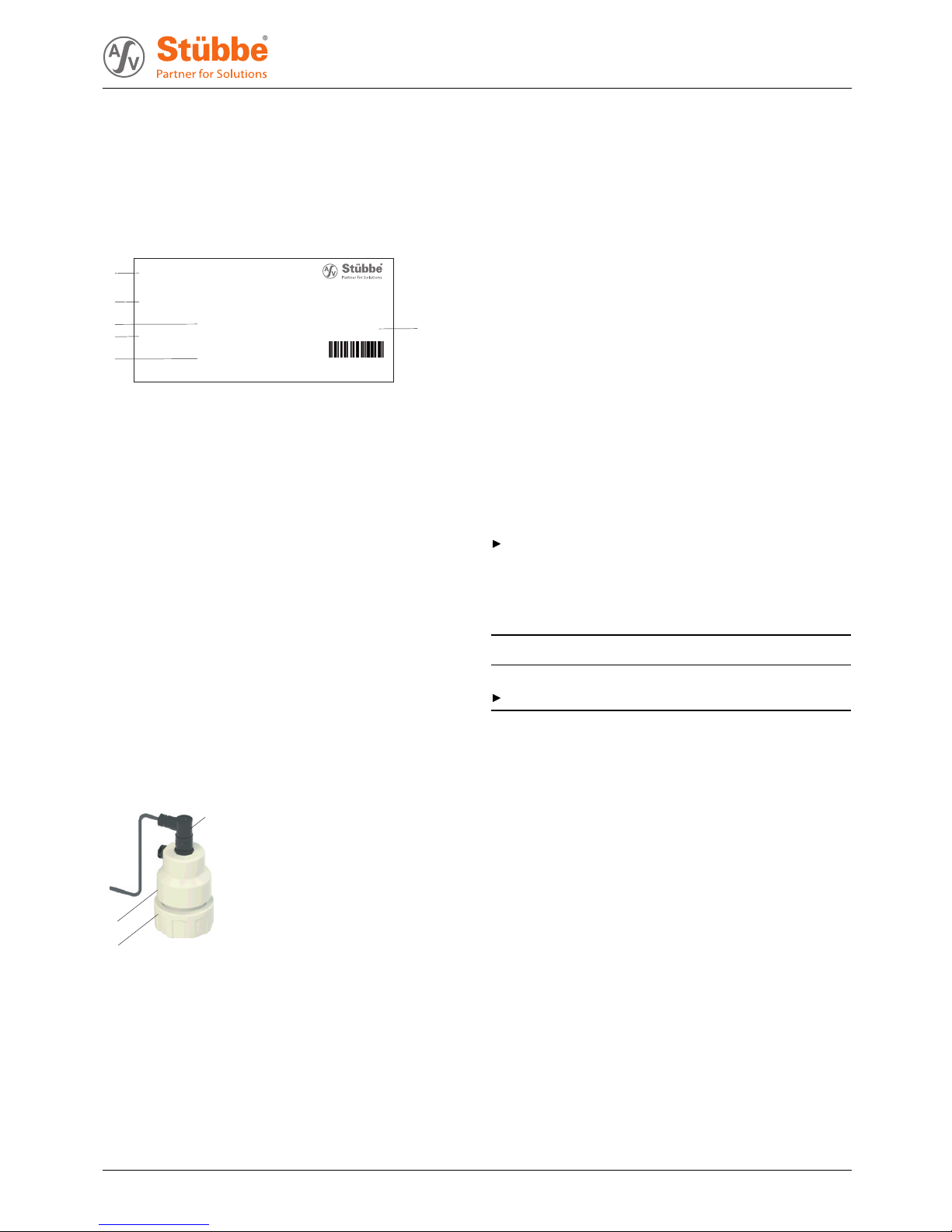
3.1 Type plate
PTM C2
Drucksensor
Messbereich 0-10bar
18-30V DC Id.No.
140557
Anschluss PP DN25
Material PP
EPDM
1304-05371
1
2
3
4
5
6
4-20mA 2-Leiter
Fig. 1 Type plate
1Devicetype
2 Pressure measurement range
3 Output
4 Connection (material and nominal diameter)
5 Gasket material
6 ID number
Device types
• PTM C2 – Standard, current output
3.2 Description
The device measures the pressure of a liquid medium. It trans-
mits the measured value via a current output.
3.3 Layout
3.3.1 Layout
2
3
1
Fig. 2 Layout
1 Plug connector
2 Sensor housing
3 Process connection
4 Transport, Storage and
Disposal
4.1 Unpacking and inspection on delivery
1. Unpack the device when received and inspect it for trans-
port damage and completeness.
2. Check that the information on the type plate agrees with
the order/design data.
3. Report any transport damage to the manufacturer immedi-
ately.
4. If fitted immediately: Dispose of packaging material
according to local regulations.
–Iffitted at a later point: leave device in its original pack-
aging.
4.2 Transportation
Device should preferably be transported in the original
packaging.
4.3 Storage
NOTE
Material damage due to inappropriate storage!
Store the device properly.
1. Make sure the storage room meets the following condi-
tions:
–Dry
– Frost-free
– Vibration-free
– Not in direct sunlight
– Storage temperature +10 °C to +60 °C
2. Device should preferably be stored in the original packag-
ing.
300 196 BA-2016.11.24 EN PTM C2 5
Installation and connection
4.4 Disposal
Plastic parts can be contaminated by poisonous or radioac-
tive media to such an extent that cleaning will not be suffi-
cient.
WARNING
Risk of poisoning and environmental damage from
medium.
Use personal protective equipment when carrying out any
work on the device.
Prior to the disposal of the device: Neutralize residues of
medium in the device.
1. Remove battery and dispose of in accordance with local
regulations.
2. Remove electronic parts and dispose of in accordance with
local regulations.
3. Dispose of plastic parts in accordance with local regula-
tions.
5 Installation and connection
5.1 Check operating conditions
1. Ensure the required operating conditions are met:
– Resistance of body and seal material to the medium
(→resistance lists).
– Media temperature (→9.1 Technical specifications,
Page 8).
– Working pressure (→9.1 Technical specifications,
Page 8).
2. Consult with the manufacturer regarding any other use of
the device.
5.2 Installing device in the process
pipework
Process pipework has been properly prepared.
Process pipework has been secured against unintentional
opening with shut-off values.
Avoidance of medium buildup.
Select installation location so that no build-up or crystalliza-
tion is possible.
WARNING
Risk of injury and poisoning due to medium spraying out.
Use personal protective equipment when carrying out any
work on the fitting.
1. Unscrew union nut.
2. Insert union nut on to the spool piece of the process
pipework.
Check mounting direction.
3. Weld device insert to the process pipework spool piece.
4. Check O-ring fitting.
5. Connect device to the process pipework. Tighten union nut
by hand only.
5.3 Performing the hydrostatic test
Perform hydrostatic test using neutral medium, e.g. water.
1. Pressurize the device, ensuring
– Test pressure < 1.5 x PN(Nominal pressure)
– Test pressure < PN+5bar
– Test pressure < permissible system pressure
2. Check that the device is not leaking.
5.4 Electrical connection of device
Device is connected to the process pipework.
Power supply switched off and secured against being
switched back on again.
Cable without shielding can be used to connect the device.
If electromagnetic interference is anticipated, then shielded
cable must be used.
1. Cut sensor cable supplied to length.
2. Fit plug (→9.3 Plug assignment, Page 8).
3. Connect sensor housing with sensor cable.
6 PTM C2 BA-2016.11.24 EN 300 196

Maintenance
6 Operation
6.1 Initial start-up
Device is connected properly to the process pipework.
Device is connected properly with the power supply and
ready for operation.
For this purpose, the current output for pressure must
be displayed in the higher-level controller as a measured
value.
After starting the higher-level controller, the device trans-
mits the pressure as current signal (4 … 20 mA).
7 Maintenance
WARNING
Risk of injury and poisoning due to hazardous or hot
media.
Use personal protective equipment for all work on the
device.
Allowdevicetocool.
Make sure the device is depressurized.
Block the media supply to the device.
Empty the process pipework, safely collect the media and
dispose of it in accordance with environmental regulations.
Switch off the power supply to the system.
Secure power supply against being switched back on
again.
Provide warning of maintenance and repair work and set
up warning signs.
7.1 Servicing
Interval Action
As necessary • Cleandevicewithadampcloth.
Six-monthly Visual and function check:
• Normal operating conditions
unchanged
•Noleaks
• No unusual operating noises or
vibrations
Tab. 3 Servicing activities
Perform maintenance tasks according to the table.
7.2 Maintenance
7.2.1 Removing the device
System is empty.
System has been flushed.
System is depressurized.
System has cooled down.
System is secured against beingswitchedbackonagain.
1. Unplug connection cable.
2. Disassemble device from the process pipework.
3. Decontaminate device if required.
7.2.2 Replacement parts and return
1. Have the following information ready to hand when order-
ing spare parts (→3.1Typeplate,Page5).
–Devicetype
– ID number
– Nominal pressure and diameter
– Connection and gasket material
2. Please complete and enclose the document of compliance
for returns (→www.asv-stuebbe.com/service/downloads).
3. Only use spare parts from ASV Stübbe.
300 196 BA-2016.11.24 EN PTM C2 7

Appendix
8 Troubleshooting
WARNING
Risk of injury and poisoning due to hazardous media liq-
uids!
Use personal protective equipment when carrying out any
work on the device.
Error Possible cause Corrective action
Medium is leaking
out of the flange
Pre-tension of the
O-ring too small
Retighten
union nut by
hand.
Tab. 4 Troubleshooting
9 Appendix
9.1 Technical specifications
Technical data (→Data sheet).
9.2 Dimensions
Dimensions (→Data sheet).
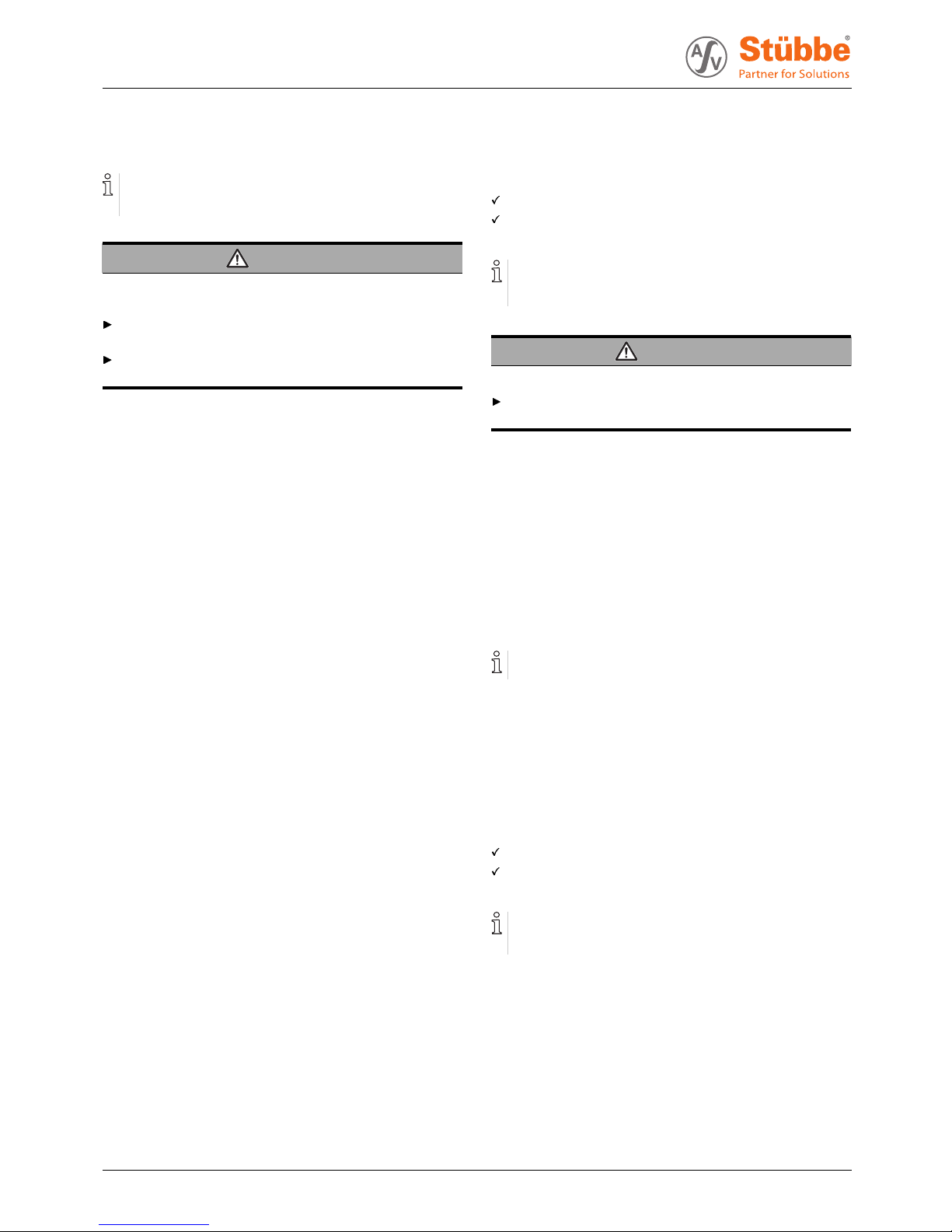
9.3 Plug assignment
2
34
1
Fig. 3 Connection diagram
1Signal(+)
2 Signal (-)
3n.c.
4n.c.
8 PTM C2 BA-2016.11.24 EN 300 196
Table of contents
Other Stübbe Accessories manuals


 Specification sheet")


