Lightspeed Systems Lightspeed Rocket Manual

1800 19th Street /Bakersfield, CA 93301 /Tel: 661.716.7600 /Toll Free: 877.447.6244 / www.lightspeedsystems.com
Lightspeed Rocket
Hardware Installation Guide

Lightspeed Hardware Installation Guide 2
Section 1 Safety Notice and Warnings . . . . . . . . . . . . . . . . . . . . . . . . . . . . . . . . . . . . . . . . . . . . . . . 3
Section 2 Ratings . . . . . . . . . . . . . . . . . . . . . . . . . . . . . . . . . . . . . . . . . . . . . . . . . . . . . . . . . . . . . . . . 3
Section 3 Electrical and General Safety Guidelines . . . . . . . . . . . . . . . . . . . . . . . . . . . . . . . . . . . . . . 4
Section 4 Unpacking the Appliance . . . . . . . . . . . . . . . . . . . . . . . . . . . . . . . . . . . . . . . . . . . . . . . . . . 6
Section 5 Site Preparation . . . . . . . . . . . . . . . . . . . . . . . . . . . . . . . . . . . . . . . . . . . . . . . . . . . . . . . . . 7
Section 6A 4-Post Rack Installation . . . . . . . . . . . . . . . . . . . . . . . . . . . . . . . . . . . . . . . . . . . . . . . . . . . 8
Section 6B 2-Post Rack Installation . . . . . . . . . . . . . . . . . . . . . . . . . . . . . . . . . . . . . . . . . . . . . . . . . . . 9
Section 7A Lightspeed Rocket Email Manager-R Rear Panel Connections . . . . . . . . . . . . . . . . . . . . . 10
Section 7B Lightspeed Rocket Web Access Manager-R Rear Panel Connections . . . . . . . . . . . . . . . 11
Section 7C Lightspeed Rocket Web Access Manager-RQ Rear Panel Connections . . . . . . . . . . . . . 12
Section 7D Lightspeed Rocket Web Access Manager-1Gb Rear Panel Connections . . . . . . . . . . . . 13
Section 7E Lightspeed Rocket Web Access Manager-10Gb Rear Panel Connections . . . . . . . . . . . 14
Section 7F Lightspeed Total Traffic Control Rocket-R Rear Panel Connections . . . . . . . . . . . . . . . . . 15
Section 8 End User License Agreement (EULA) and Front Panel Operation . . . . . . . . . . . . . . . . . . 16
Section 9 Ship Carton Packing/Repacking Instructions . . . . . . . . . . . . . . . . . . . . . . . . . . . . . . . . . . 17
Table of Contents

Lightspeed Hardware Installation Guide 3
1. Safety Notice and Warnings
2. Ratings
FCC Notice
This device complies with part 15 of the FCC Rules. Operation is subject to the following two conditions:
1. This device may not cause harmful interference.
2. This device must accept any interference received, including interference that may cause
undesired operation.
No Telecommunications Network Voltage (TNV)-connected PCBs shall be installed.
This class A digital apparatus complies with Canadian ICES-003.
Cet appareil numérique de la classe A est conforme à la norme NMB-003 du Canada.
CE Mark Warning
This is a Class A product. In a domestic environment, this product may cause radio interference,
in which case the user may be required to take adequate measures.
VCCI Warning
This is a product of VCCI Class A Compliance.
Environmental Warning
Perchlorate Material - special handling may apply. See www.dtsc.ca.gov/hazardouswaste/perchlorate.
This notice is required by California Code of Regulations, Title 22, Division 4.5, Chapter 33: Best Management
Practices for Perchlorate Materials. This product/part includes a battery that contains Perchlorate material.
AC input voltage: 100 - 240 VAC (auto-range)
Rated input current: 8.0 / 4.0
Hz: 50 / 60

Lightspeed Hardware Installation Guide 4
3. Electrical and General Safety Guidelines
CAUTION
This appliance is intended for installation in restricted areas only. Initial setup and maintenance
should be performed by qualified personnel.
CAUTION
Power down the appliance following the operating system’s proper power down procedure
from the front panel. Unplug all AC power cord(s) before servicing.
CAUTION
To avoid electrical shock, check the power cords as follows.
•This product is to be installed in Restricted Access Location only.
•Use the exact type of power cords required.
•Use power cord(s) that came with safety certifications.
•Power cord(s) must comply with AC voltage requirements in your region.
•The power cord plug cap must have an electrical current rating that is at least 125% of
the electrical current rating of this product.
•The power cord plug cap that plugs into the AC receptacle on the power supply must be
an IEC 320, sheet C13, type female connector.
•Plug the power cord(s) into a socket that is properly grounded before turning on the power.
CAUTION
Required operating conditions for the appliance are -
•Temperature: 10 to 35oC.
•Humidity, non-condensing: 8 to 90%.
CAUTION
Risk of explosion if the battery is installed upside down or is replaced by an incorrect type.
Dispose of used batteries according to the instructions.
DISPOSING OF BATTERY BACKUP UNITS - IF APPLICABLE
WARNING
If the BBU is damaged in any way, toxic chemicals may be released.
The material in the battery pack contains heavy metals that can contaminate the environment.
Federal, state, and local regulations prohibit the disposal of rechargeable batteries in public landfills.
Be sure to recycle the old battery packs properly. Comply with all applicable battery disposal and
hazardous material handling laws and regulations in the country or other jurisdiction where you are
using the BBU.
WARNING
There is danger of an explosion if the battery is incorrectly replaced. Replace it only with the same
or equivalent type recommended by the manufacturer. Dispose of used batteries according to the
manufacturer’s instructions.

Lightspeed Hardware Installation Guide 5
3. Electrical and General Safety Guidelines (continued)
WARNING
Disconnect the power supply at the circuit breaker before accessing any components.
Turning off the system power supply switch does not reduce the risk of electrical shock
from the power supply terminal block.
CAUTION
•To prevent the unit from overheating, never install the appliance in an enclosed area that is
not properly ventilated or cooled. For proper airflow, keep the front and back sides of the
appliance clear of obstructions and away from the exhaust of other equipment.
•Be aware of the locations of the power switches on the chassis and in the room, so you
can disconnect the power supply if an accident occurs.
•Take extra precautionary measures when working with high voltage components.
Do not work alone.
•Before removing or installing main system components, be sure to disconnect the
power first. Turn off the system before you disconnect the power supply.
•Use only one hand when working with powered-on electrical equipment to avoid possible
electrical shock.
•Use rubber mats specifically designed as electrical insulators when working with
computer systems.
•The power supply or power cord must include a grounding plug and must be plugged
into grounded outlets.
CAUTION
Electric Static Discharge (ESD) can damage electronic components. To prevent damage to your
system board, it is important to handle it very carefully. The following measures can prevent
ESD damage to critical components.
•Use a grounded wrist strap designed to prevent static discharge.
•Keep all components and printed circuit boards (PCBs) in their antistatic bags until ready
for use.
•Touch a grounded metal object before removing the board from the antistatic bag.
•Do not let components or PCBs come into contact with your clothing, which may retain a
charge even if you are wearing a wrist strap.
•Handle a board by its edges only; do not touch its components, peripheral chips, memory
modules or contacts.
•When handling chips or modules, avoid touching their pins.
•Put the motherboard and peripherals back into their antistatic bags when not in use.
•For grounding purposes, make sure your computer chassis provides excellent conductivity
between the power supply, the case, the mounting fasteners and the motherboard.

Lightspeed Hardware Installation Guide 6
Before you begin:
Verify that the ship kit includes two power cords, the screws, cone washers and cage
nuts (shown below) that you will need to install the appliance in your rack, the 4-post and/or
2-post rack rail bracket assemblies.
The 4-post rack assembly consists of:
•A set of long, fixed rack brackets that attach directly to the rack itself.
•A set of medium-sized adjustable rack brackets that attach to the long,
fixed rack brackets.
NOTE: See Section 6A on the page 8 of this document for the 4-post rack rail assemblies.
The 2-post rack assembly consists of:
•A set of long, fixed rack brackets.
•Three sets of short rack brackets that attach to the long fixed rack brackets.
One of these sets has threaded holes (for placement in the front) to allow the
appliance to be secured in the rack.
NOTE: See Section 6B on page 9 of this document for the 2-post rack rail assemblies.
(Eight) M5 x 12
flat head screws
(Two) 10-32 x 3/4"
pan head screws
(Twenty-two) M4 x 4
truss head screws
(Eight) M5 x 12
cone washers
(Ten) M5
Cage nuts
4. Unpacking the Appliance
NOTE: Use the hardware
supplied with your specific
rack if different from the
hardware supplied in this kit.
Hardware Kit: screws, cone washers and cage nuts

Lightspeed Hardware Installation Guide 7
Setup location, rack and appliance precautions
•Elevated Operating Ambient - If installed in a closed or multi-unit rack assembly, the operating
ambient temperature of the rack environment may be greater than room ambient. Therefore,
consideration should be given to installing the equipment in an environment compatible with the
maximum ambient temperature (Tma) specified by the manufacturer.
Always keep the rack’s front door and all panels and components on the appliances closed when
not servicing to maintain proper cooling.
•Reduced Air Flow - Installation of the equipment in a rack should be such that the amount of air flow
required for safe operation of the equipment is not compromised. Leave enough clearance,
approximately 25 inches in the front, and 30 inches in the back of the rack to enable you to access
appliance components and allow for sufficient air flow.
•Mechanical Loading - Mounting of the equipment in the rack should be such that a hazardous
condition is not achieved due to uneven mechanical loading.
ALL RACKS MUST BE MOUNTED SECURELY.
Ensure that all leveling jacks or stabilizers are
properly attached to the rack. If installing multiple appliances in a rack, make sure the overall loading
for each branch circuit does not exceed the rated capacity.
Do not slide more than one appliance out from the rack at a time. Extending more than one appliance
at a time may result in the rack becoming unstable. Install your appliance in the lower part of the rack
because of its weight and also for ease in accessing appliance components.
•Circuit Overloading - Consideration should be given to the connection of the equipment to the supply
circuit and the effect that overloading of the circuits might have on overcurrent protection and supply
wiring. Appropriate consideration of equipment nameplate ratings should be used when addressing
this concern.
•Reliable Earthing - Reliable earthing of rack-mounted equipment should be maintained. Particular
attention should be given to supply connections other than direct connections to the branch circuit
(e.g. use of power strips).
Install near appropriate AC outlets, and Ethernet hubs or individual jacks. Be sure to install an AC
Power Disconnect for the entire rack assembly. The Power Disconnect must be clearly marked.
Ground the rack assembly properly to avoid electrical shock.
5. Site Preparation

Fixed chassis rail
(attached prior to shipment)
Two 10-32 x 3/4"
truss head screws
Locking tab
*Release mechanism for the bezel
is located on this side.
Lightspeed Hardware Installation Guide 8
Two M5 x 12
flat head screws
and two cone washers
(rear)
Two cage nuts
(rear)
Outer fixed
chassis rails
4-post rack
Three cage nuts
(front)
Two M5 x 12
flat head screws
and two cone
washers
Rear medium-sized
adjustable bracket
Rack bracket tab
6A. 4-Post Rack Installation
Unpack the appliance and locate the mounting hardware
NOTE: The following installation procedures for 6a, 4-post rack
and 6b, 2-post rack are for use with the rails and hardware provided
in your ship kit. If different style rails are being used, or if your rack
requires different hardware, refer to the instructions provided with
your rail’s or rack’s ship kit.
*NOTE: Refer to your rack’s mounting hardware for the proper
size and type of screws to secure the appliance in the rack.
Step 2
•Insert a cage nut into each of the square holes in the rack
you will be using as shown (three in the front and two in
the rear). They click into place.
•Attach the rack /rail assemblies to the rack using two
M5 x 12 flat head screws and cone washers in the front
and back.
The convex side of the cone washers face toward
the rack.
•Make sure the rack / rail assemblies and screws are
aligned in the rack not only in the front and back, but
are level in height on the left and right sides for proper
alignment for appliance installation.
Step 1
•Locate the two rack rail brackets that came in your ship kit.
•Attach the medium-sized adjustable rack bracket to the
longer fixed rack bracket as shown.
•Insert the tab on the rear of the medium adjustable rack
bracket through the larger round opening on the back end
of the long fixed rack bracket and slide the long bracket
forward to keep the two brackets from coming apart. These
rail brackets slide to accommodate different rack depths.
Step 3
•Align the fixed chassis rails on the appliance with the
fixed rack rail brackets installed in the rack.
•Carefully slide the appliance into the rack until you
hear the locking tabs on each side of the fixed front
rails click into place.
•Push the appliance all the way into the rack
until it stops.
•Secure the unit in the rack using a 10-32 x 3/4”*
truss head screw (and a cage nut if not already
installed) in the center hole on each rail.

Small fixed
rack bracket
Small fixed
rack brackets with
threaded holes
Small fixed
rack brackets
Long bracket
A
B
C
B
C
A
Two M4 truss
head screws
One M4 truss
head screw
Fixed chassis rail
(attached prior to shipment)
Two 10-32 x 3/4"
truss head screws
Locking tab
*Release mechanism for the bezel
is located on this side.
Lightspeed Hardware Installation Guide 9
M5 x 12
flat head screws*
(two front and rear)
A
A
A
A
B
B
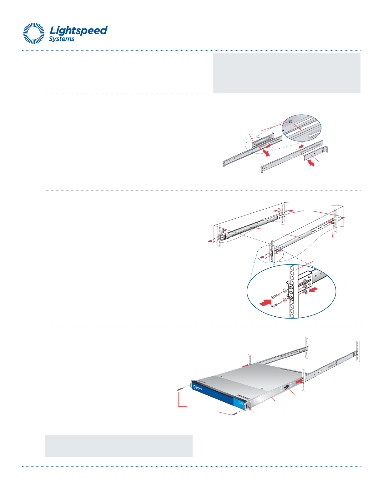
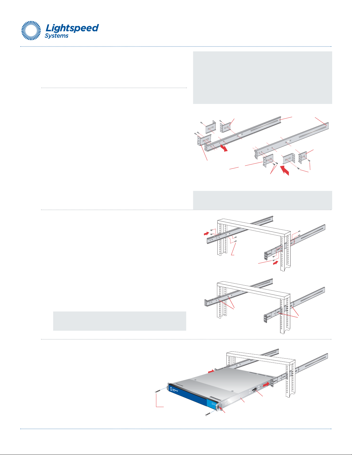
6B. 2-Post Rack Installation
Unpack the appliance and locate the mounting hardware
Step 1
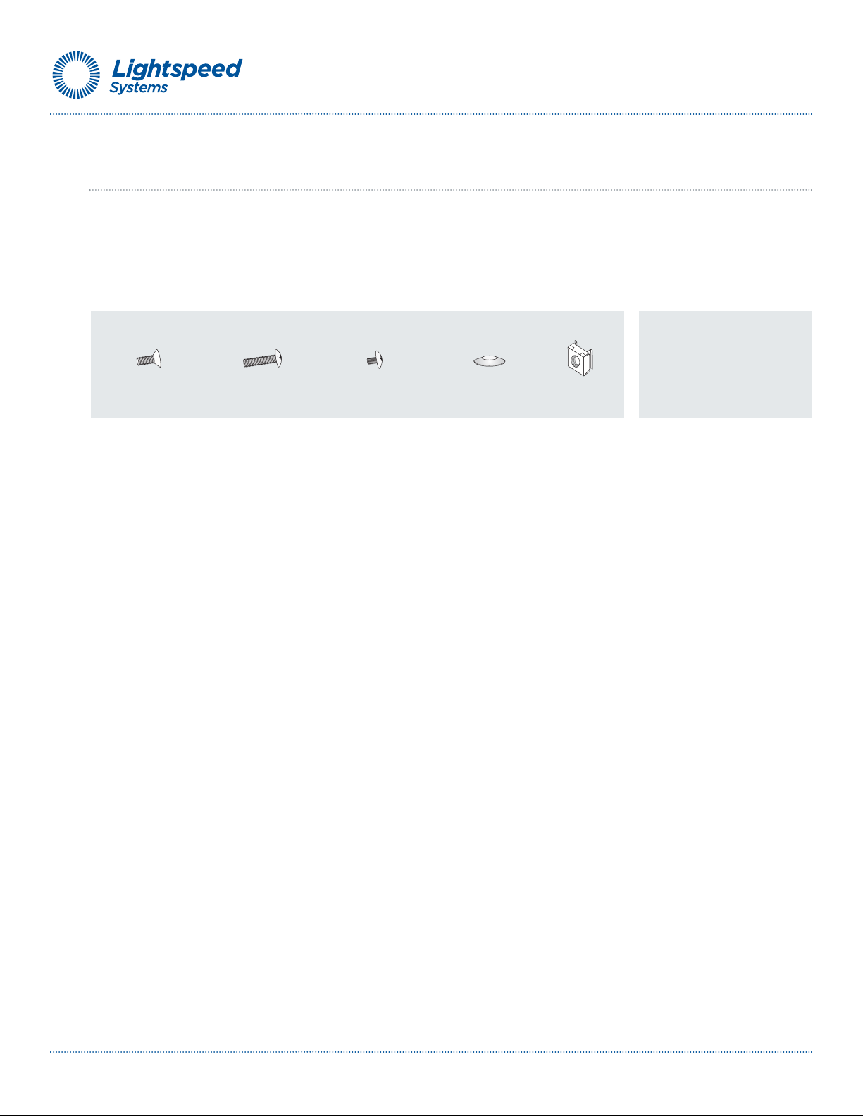
Locate the two long and six short rack brackets that came in your
ship kit.
A. Securely attach the set of short brackets with the threaded
screw holes to the long bracket in the front as shown.
Use two M4 truss head screws for each bracket.
B. Loosely attach one set of the other short brackets to the
long fixed bracket as shown using one M4 truss head screw
on each bracket. The three holes on the flap will face toward
the back for later attachment to the 2-post rack.
C. Loosely attach the remaining set of short brackets to the
long fixed bracket as shown using one M4 truss head screw
on each bracket. The three holes on the flap will face toward
the front for later attachment to the 2-post rack.
Step 2
Attach the assembled brackets to the 2-post rack.
A. Insert two M5 x 12 flat head screws through the short
brackets into the 2-post rack (in the front and back of the
rack as shown) and tighten. Make sure the brackets are
aligned and level in height, not only in the front and back
but also on the left and right sides.
B. Tighten each of the the single screws on the small fixed
brackets (located on either side of the rack) to secure the
brackets in the rack and ensure appliance stability.
Step 3
•Align the fixed chassis rails on the appliance with the fixed
rack rail brackets installed in the rack.
•Carefully slide the appliance into the rack until
you hear the locking tabs on each side of the
fixed front rails click into place.
•Push the appliance all the way back into the
rack until it stops. Secure the unit in the rack
using a 10-32 x 3/4”*truss head screw in the
center hole on each rail.
NOTE: Once the assembled rails are attached to the rack, securely
tighten the single screws on steps Band C.
*Refer to your rack's mounting hardware for the proper size
and type of screws to secure the appliance in the rack.
NOTE 1: The following installation procedures for 6B, are for use
with the rails and hardware provided in your ship kit. If different
style rails are being used, or if your rack requires different hardware,
refer to the instructions provided with your rail’s or rack’s ship kit.
NOTE 2: When removing the appliance from the 2-post rack (Step
3 below), you will need to press down on the right locking tab and
lift up on the left locking tab in order to release it from the rack.
Carefully slide it out supporting the unit on both sides at all times.

Lightspeed Hardware Installation Guide 10
7A. Lightspeed Rocket Email Manager-R Rear Panel Connections
Power Good LEDs
AC Power Inlets
Power Supply Locks
Mouse Port
COM Port
VGA Port
Network Interface Connectors
USB Ports
Keyboard Port
Ethernet
Cable
Management
Port
Local
Area
Network
1
2
Power Cords
4
4
NOTE: The Power Good LED on the rear panel will illuminate
green during normal operation. During standby or when it is
powered down, the Power Good LED will be yellow.
Step 1 Connect one end of the yellow Ethernet cable into the Ethernet port labeled MANAGEMENT.
Step 2 Connect the other end of the yellow Ethernet cable into an available switch port on your
Local Area Network. This port will require Internet access.
Step 3 Please review the latest Lightspeed Rocket Email Manager Product Manual on the Lightspeed Wiki
at (http://wiki.lightspeedsystems.com/LSREM).
Step 4 Connect the power cords.
Step 5 Proceed to Front Panel Operation on page 16.

Lightspeed Hardware Installation Guide 11
7B. Lightspeed Rocket Web Access Manager-R Rear Panel Connections
Mouse Port
Network Interface
Connectors
Internal
External
Power Cords
Power Good LEDs
AC Power Inlets
Power Supply Locks
Keyboard Port
VGA Port
COM Port
USB Ports
Ethernet
Cable
Management
Port
Local
Area
Network
2
4
4
1
NOTE: The Power Good LED on the rear panel will illuminate
green during normal operation. During standby or when it is
powered down, the Power Good LED will be yellow.
Step 1 Connect one end of the yellow Ethernet cable into the Ethernet port labeled MANAGEMENT.
Step 2 Connect the other end of the yellow Ethernet cable into an available switch port on your
Local Area Network. This port will require Internet access.
Itis very important that ONLY theManagement NIC is connected at this time. DO NOT connect
theExternal or Internal NIC cards untilinstructed to dosoby aLightspeed Support Engineer.
Step 3 Please review the latest Lightspeed Rocket Web Access Manager Product Manual on the
Lightspeed Wiki at (http://wiki.lightspeedsystems.com/LSRWAM).
Step 4 Connect the power cords.
Step 5 Proceed to Front Panel Operation on page 16.

Lightspeed Hardware Installation Guide 12
7C. Lightspeed Rocket Web Access Manager-RQ Rear Panel Connections
Mouse Port
Network Interface
Connectors
Internal 0
External 0
Power Cords
Power Good LEDs
AC Power Inlets
Power Supply Locks
Keyboard Port
VGA Port
COM Port
USB Ports
Ethernet
Cable
Management
Port
Local
Area
Network
2
4
4
1
Internal 1
External 1
NOTE: The Power Good LED on the rear panel will illuminate
green during normal operation. During standby or when it is
powered down, the Power Good LED will be yellow.
Step 1 Connect one end of the yellow Ethernet cable into the Ethernet port labeled MANAGEMENT.
Step 2 Connect the other end of the yellow Ethernet cable into an available switch port on your
Local Area Network. This port will require Internet access.
Itis very important that ONLY theManagement NIC is connected at this time. DO NOT connect
theExternal or Internal NIC cards untilinstructed to dosoby aLightspeed Support Engineer.
Step 3 Please review the latest Lightspeed Rocket Web Access Manager Product Manual on the
Lightspeed Wiki at (http://wiki.lightspeedsystems.com/LSRWAM).
Step 4 Connect the power cords.
Step 5 Proceed to Front Panel Operation on page 16.

Lightspeed Hardware Installation Guide 13
7D. Lightspeed Rocket Web Access Manager-1Gb Rear Panel Connections
Mouse Port
Network Interface
Connectors
Power Cords
Power Good LEDs
AC Power Inlets
Power Supply Locks
Keyboard Port
VGA Port
COM Port
USB Ports
Ethernet
Cable
Management
Port
Local
Area
Network
2
4
4
1
Internal
External
NOTE: The Power Good LED on the rear panel will illuminate
green during normal operation. During standby or when it is
powered down, the Power Good LED will be yellow.
Step 1 Connect one end of the yellow Ethernet cable into the Ethernet port labeled MANAGEMENT.
Step 2 Connect the other end of the yellow Ethernet cable into an available switch port on your
Local Area Network. This port will require Internet access.
Itis very important that ONLY theManagement NIC is connected at this time. DO NOT connect
theExternal or Internal NIC cards untilinstructed to dosoby aLightspeed Support Engineer.
Step 3 Please review the latest Lightspeed Rocket Web Access Manager Product Manual on the
Lightspeed Wiki at (http://wiki.lightspeedsystems.com/LSRWAM).
Step 4 Connect the power cords.
Step 5 Proceed to Front Panel Operation on page 16.

Lightspeed Hardware Installation Guide 14
7E. Lightspeed Rocket Web Access Manager-10Gb Rear Panel Connections
Mouse Port
Network Interface
Connectors
Power Cords
Power Good LEDs
AC Power Inlets
Power Supply Locks
Keyboard Port
VGA Port
COM Port
USB Ports
Ethernet
Cable
Management
Port
Local
Area
Network
2
4
4
1
Internal
External
NOTE: The Power Good LED on the rear panel will illuminate
green during normal operation. During standby or when it is
powered down, the Power Good LED will be yellow.
Step 1 Connect one end of the yellow Ethernet cable into the Ethernet port labeled MANAGEMENT.
Step 2 Connect the other end of the yellow Ethernet cable into an available switch port on your
Local Area Network. This port will require Internet access.
Itis very important that ONLY theManagement NIC is connected at this time. DO NOT connect
theExternal or Internal NIC cards untilinstructed to dosoby aLightspeed Support Engineer.
Step 3 Please review the latest Lightspeed Rocket Web Access Manager Product Manual on the
Lightspeed Wiki at (http://wiki.lightspeedsystems.com/LSRWAM).
Step 4 Connect the power cords.
Step 5 Proceed to Front Panel Operation on page 16.

Lightspeed Hardware Installation Guide 15
7E. Lightspeed Total Traffic Control Rocket-R Rear Panel Connections
Mouse Port
Network Interface
Connectors
Internal
External
Power Cords
Power Good LEDs
AC Power Inlets
Power Supply Locks
Keyboard Port
VGA Port
COM Port
USB Ports
Ethernet
Cable
Management
Port
Local
Area
Network
2
4
4
1
NOTE: The Power Good LED on the rear panel will illuminate
green during normal operation. During standby or when it is
powered down, the Power Good LED will be yellow.
Step 1 Connect one end of the yellow Ethernet cable into the Ethernet port labeled MANAGEMENT.
Step 2 Connect the other end of the yellow Ethernet cable into an available switch port on your
Local Area Network. This port will require Internet access.
Itis very important that ONLY theManagement NIC is connected at this time. DO NOT connect
theExternal or Internal NIC cards untilinstructed to dosoby aLightspeed Support Engineer.
Step 3 Please review the latest Lightspeed Total Traffic Control Rocket Product Manual on the
Lightspeed Wiki at (http://wiki.lightspeedsystems.com/TTC).
Step 4 Connect the power cords.
Step 5 Proceed to Front Panel Operation on page 16.

Lightspeed Hardware Installation Guide 16
Power Button
8. Front Panel Operation
By powering on the appliance you agree to all terms and conditions included in the
End User License Agreement (EULA) located at eula.lightspeedsystems.com
Power on the appliance
•Remove the front bezel by pressing in on the right side of the bezel to release it
(see the diagram in Step 3 on page 8 or 9 for the location of the release tab).
•Press the power button located on the far right on the front side of the appliance.
•Once the system has been powered on, replace the bezel.

Lightspeed Hardware Installation Guide 17
9. Ship Carton Packing/Repacking Instructions
PLEASE HOLD ON TO THESE INSTRUCTIONS AND THE BOX
To ensure the Lightspeed Systems server a safe return, please follow these steps.
Step 1
•Open up the original shipping box.
•Remove packing material leaving the large gray section
of foam located in the bottom of the carton and the two
side sections of white foam in position as shown.
Step 2
•Remove the front bezel if it is still installed on the server,
re-wrap in plastic bubble wrap and put it aside for later
packing.
•Put the server back in its plastic bag and fit it in between
the two side sections of white foam pieces as shown.
•Place the rack kit along one edge of the box.
Step 3
•Place the second large section of gray foam with the
opening for the smaller parts carton facing up on top of
the previously packed server and rail kit carton.
•Put the bezel, all of the Ethernet cables and power cords in
the smaller parts carton. Place this carton in the opening
in the top gray foam.
Step 4
•Close the flaps and securely tape the carton closed.
You’ve prepared the server for a safe return!
•Contact Lightspeed Systems at 877-447-6244 or
RMA and send out UPS to pick it up.
Bottom foam Side foam sections
Small parts carton Top foam section
Rack kit cartonServer

Copyright ©2010-2011 Lightspeed Systems, Inc. All rights reserved.
Lightspeed Systems
1800 19th Street
Bakersfield, CA 93301
Corporate Tel: Voice: 661.716.7600
Fax: 661.716.8600
Toll Free: 877.447.6244
Support Phone: 800.444.9267
www.lightspeedsystems.com
Lightspeed Systems Europe:
Whitegates
Alexander Lane
Shenfield
Essex
CM15 8QF
Tel: 01277.240.630
Fax: 01277.240.641
www.lseurope.com
Other manuals for Lightspeed Rocket
1
Table of contents
Popular Network Hardware manuals by other brands

Broadcast Tools
Broadcast Tools WebSwitch Installation and operation manual

ZUM Radio
ZUM Radio ZUMspot RPi troubleshooting guide

Buffalo
Buffalo LinkStation 500 user manual

Riverbed
Riverbed SteelCentral SCNP-04280 Series Appliance installation guide

Lanner
Lanner NCA-6530 user manual

ADC Kentrox
ADC Kentrox ISDN NT1 1010 user manual