Lightware MODEX-OPTS-TX User manual

MODEX-OPTS-TX
MODEX-OPTM-TX
MODEX-OPTS-RX
MODEX-OPTM-RX
User’s Manual


25G-FR160
User’s Manual
Section 1. Introduction Page 3 / 113
SAFETY INSTRUCTIONS
Class I apparatus construction. This equipment must be used with a main power system
with a protective earth connection. The third (earth) pin is a safety feature, do not bypass
or disable it.
This equipment should be operated only from the power source indicated on the product.
To disconnect the equipment safely from power, remove the power cord from the rear of
the equipment, or from the power source. The MAINS plug is used as the disconnect
device, the disconnect device shall remain readily operable.
There are no user-serviceable parts inside of the unit. Removal of the top cover will expose
dangerous voltages. To avoid personal injury, do not remove the top cover. Do not operate
the unit without the cover installed.
The apparatus shall not be exposed to dripping or splashing and that no objects filled with
liquids, such as vases, shall be placed on the apparatus.
The apparatus must be safely connected to multimedia systems. Follow instructions
described in this manual.
WEEE ( Waste Electrical & Electronic Equipment )
Correct Disposal of This Product
This marking shown on the product or its literature, indicates that it should not be disposed
with other household wastes at the end of its working life. To prevent possible harm to the
environment or human health from uncontrolled waste disposal, please separate this from
other types of wastes and recycle it responsibly to promote the sustainable reuse of
material resources.
Household users should contact either the retailer where they purchased this product, or
their local government office, for details of where and how they can take this item for
environmentally safe recycling.
Business users should contact their supplier and check the terms and conditions of the
purchase contract. This product should not be mixed with other commercial wastes for
disposal.
Caution: Laser product
This laser product is designated as Class 1M, wavelengths are 850 nm, 1310 nm, 1490
nm, 1550 nm.
LASER RADIATION
DO NOT VIEW DIRECTLY WITH
OPTICAL INSTRUMENTS
CLASS 1M LASER PRODUCT

Page 4 / 113 Section 1. Introduction
DECLARATION OF CONFORMITY
We,
Lightware Kft. 1071 Budapest Peterdy str. 15 HUNGARY
as manufacturer declare, that the products
MODEX-OPTS-TX
MODEX-OPTM-TX
MODEX-OPTS-RX
MODEX-OPTM-RX
( Computer Monitor Extender )
in accordance with the EMC Directive 2004/108/EC and the Low Voltage Directive
2006/95/EEC are in conformity with the following standards:
EMI/EMC .................... EN 55103-1 E3, EN 55103-2
Safety .......................................... EN 60065 Class I
Date: 1 April 2014
Name: Gergely Vida ( Managing Director )
Signed:

25G-FR160
User’s Manual
Section 1. Introduction Page 5 / 113
Table of contents
1. INTRODUCTION...................................................................................................................... 9
1.1. BOX CONTENTS................................................................................................................... 9
1.2. DESCRIPTION...................................................................................................................... 9
1.3. FEATURES........................................................................................................................ 10
1.4. APPLICATIONS .................................................................................................................. 11
2. CONTROLS AND CONNECTIONS....................................................................................... 12
2.1. MODEX CONCEPT............................................................................................................ 12
2.2. FRAMES ........................................................................................................................... 13
2.2.1. Transmitter front view ............................................................................................. 13
2.2.2. Receiver front view ................................................................................................. 14
2.3. REAR VIEW....................................................................................................................... 15
2.4. MEDIA CONNECTORS......................................................................................................... 15
2.5. VIDEO &AUDIO MODULES.................................................................................................. 16
2.6. INTERFACE MODULES........................................................................................................ 17
2.7. ELECTRICAL CONNECTIONS ............................................................................................... 18
2.7.1. Fiber optical connectors.......................................................................................... 18
2.7.2. HDMI inputs and outputs ........................................................................................ 18
2.7.3. DVI inputs and outputs............................................................................................ 19
2.7.4. DisplayPort input and output................................................................................... 19
2.7.5. BNC connectors (SDI) ............................................................................................ 20
2.7.6. Ethernet port ........................................................................................................... 20
2.7.7. Symmetrical analog stereo audio ........................................................................... 20
2.7.8. S/PDIF digital audio input and output ..................................................................... 21
2.7.9. IR connectors.......................................................................................................... 21
2.7.10. RS-232 / RS-422 port ............................................................................................. 21
2.7.11. Neutrik power connector......................................................................................... 22
3. TECHNOLOGIES................................................................................................................... 23
3.1. UNDERSTANDING EDID..................................................................................................... 23
3.1.1. Basics...................................................................................................................... 23
3.1.2. Common problems related to EDID........................................................................ 23
3.2. ADVANCED EDID MANAGEMENT ........................................................................................ 24
3.3. HDCP MANAGEMENT........................................................................................................ 24
3.3.1. Protected and unprotected content......................................................................... 24
3.3.2. Real life examples................................................................................................... 25
4. INSTALLATION..................................................................................................................... 26
4.1. CONNECTING DEVICES ...................................................................................................... 26
4.2. SERIAL DEVICES................................................................................................................ 27
4.2.1. General information about serial communication ................................................... 27
4.2.2. Example connection diagrams................................................................................ 27
4.3. MOUNTING OPTIONS.......................................................................................................... 28
4.3.1. Rack shelf mounting (with 1U high rack shelf) ....................................................... 28
4.3.2. Truss mounting (with Mounting bracket V2)........................................................... 28
4.3.3. Through furniture mounting (with Mounting bracket V2) ........................................ 28
5. FRONT PANEL OPERATIONS............................................................................................. 29
5.1. FRONT PANEL MENU.......................................................................................................... 29
5.2. INFO MENU ....................................................................................................................... 30
5.3. SETTINGS MENU................................................................................................................ 30
5.3.1. Network settings ..................................................................................................... 30
5.3.2. System settings....................................................................................................... 31
5.4. MODULES MENU................................................................................................................ 32
5.4.1. MODEX-PH-OPTS.................................................................................................. 32
5.4.2. MODEX-AV-HDMI-OM and MODEX-AV-HDMI14-OM .......................................... 32
5.4.3. MODEX-AV-HDMI-DVI-IM and MODEX-AV-HDMI-DVI-4K-IM.............................. 32
5.4.4. MODEX-IF-AUD...................................................................................................... 33

Page 6 / 113 Section 1. Introduction
5.4.5. MODEX-IF-RS232-IR ............................................................................................. 33
5.5. CROSSPOINTS MENU......................................................................................................... 34
5.6. USB K&M MENU .............................................................................................................. 34
5.7. EDID MENU (TRANSMITTER).............................................................................................. 34
5.7.1. Viewing and changing the emulated EDID............................................................. 34
5.8. EDID MENU (RECEIVER).................................................................................................... 35
5.9. PRESETS MENU................................................................................................................. 35
5.9.1. Applying a preset .................................................................................................... 35
6. WEB CONTROL –USING THE BUILT-IN WEBSITE .......................................................... 36
6.1. NETWORK STRUCTURE...................................................................................................... 36
6.1.1. IP settings ............................................................................................................... 36
6.1.2. Establishing the connection.................................................................................... 36
6.2. LAYOUT OF BUILT-IN WEB................................................................................................... 37
6.3. CROSSPOINT MENU........................................................................................................... 38
6.3.1. Video crosspoint ..................................................................................................... 39
6.3.2. Audio crosspoint ..................................................................................................... 39
6.3.3. Infra crosspoint ....................................................................................................... 40
6.3.4. Serial crosspoint ..................................................................................................... 41
6.4. MODULE PROPERTIES AND SETTINGS ................................................................................. 42
6.4.1. Optical link quality................................................................................................... 43
6.4.2. Video modules ........................................................................................................ 43
6.4.3. Audio modules ........................................................................................................ 43
6.5. PORT PROPERTIES AND SETTINGS...................................................................................... 45
6.5.1. Analog audio input port........................................................................................... 47
6.5.2. Analog audio output port......................................................................................... 47
6.5.3. HDMI output port..................................................................................................... 47
6.5.4. HDMI input port....................................................................................................... 47
6.5.5. SDI port................................................................................................................... 48
6.5.6. IR port ..................................................................................................................... 49
6.5.7. RS-232 port............................................................................................................. 49
6.6. EDID MENU...................................................................................................................... 50
6.6.1. About EDID memory (transmitter) .......................................................................... 50
6.6.2. EDID types.............................................................................................................. 50
6.6.3. Advanced EDID Management ................................................................................ 51
6.6.4. Changing emulated EDID....................................................................................... 51
6.6.5. Learning an EDID ................................................................................................... 52
6.6.6. Exporting an EDID.................................................................................................. 52
6.6.7. Importing an EDID .................................................................................................. 52
6.6.8. EDID Summary window.......................................................................................... 52
6.6.9. Creating an EDID.................................................................................................... 52
6.6.10. Editing an EDID ...................................................................................................... 53
6.6.11. Deleting EDID(s)..................................................................................................... 53
6.7. CONTROL MENU................................................................................................................ 53
6.7.1. Ethernet tab ............................................................................................................ 53
6.7.2. USB tab................................................................................................................... 54
6.8. EVENT MANAGER .............................................................................................................. 54
6.8.1. The event area........................................................................................................ 55
6.8.2. Wizard mode........................................................................................................... 56
6.8.3. Advanced mode...................................................................................................... 57
6.8.4. Save, load or clear an event................................................................................... 58
6.9. SETTINGS MENU................................................................................................................ 59
6.9.1. Core tab .................................................................................................................. 59
6.9.2. Network tab............................................................................................................. 59
6.9.3. Status tab................................................................................................................ 60
6.9.4. System log tab ........................................................................................................ 60
6.9.5. Presets tab.............................................................................................................. 61
6.9.6. Backup tab.............................................................................................................. 62
6.9.7. Lock tab .................................................................................................................. 63
6.10. ADVANCED VIEW............................................................................................................... 64

25G-FR160
User’s Manual
Section 1. Introduction Page 7 / 113
7. PROGRAMMER’S REFERENCE.......................................................................................... 65
7.1. LW3 PROTOCOL –OVERVIEW............................................................................................ 65
7.1.1. Elements of tree structure....................................................................................... 65
7.1.2. Escaping ................................................................................................................. 67
7.1.3. Error messages....................................................................................................... 68
7.1.4. Prefix summary....................................................................................................... 68
7.2. COMMANDS ...................................................................................................................... 69
7.2.1. Get all children of a node........................................................................................ 69
7.2.2. Get all properties and methods of a node............................................................... 69
7.2.3. Get all child nodes, properties and methods of a node.......................................... 70
7.2.4. Set command.......................................................................................................... 70
7.2.5. Invocation................................................................................................................ 71
7.2.6. Subscription ............................................................................................................ 71
7.2.7. Notifications about the changes of the properties .................................................. 73
7.2.8. Signature................................................................................................................. 73
7.2.9. Manual .................................................................................................................... 74
7.2.10. Formal definitions.................................................................................................... 74
7.3. LW3 PROTOCOL TREE....................................................................................................... 74
7.3.1. /REMOTE................................................................................................................ 75
7.3.2. /PRESETS.............................................................................................................. 75
7.3.3. /MANAGEMENT/.................................................................................................... 75
7.3.4. /EDID....................................................................................................................... 76
7.3.5. /MEDIA.................................................................................................................... 76
7.3.6. /SYS........................................................................................................................ 76
7.4. VIDEO PORT AND CROSSPOINT SETTINGS ........................................................................... 76
7.4.1. Query the video crosspoint setting ......................................................................... 76
7.4.2. Query the status of source ports............................................................................. 77
7.4.3. Mute an input port................................................................................................... 78
7.4.4. Unmute an input port .............................................................................................. 78
7.4.5. Lock an input port ................................................................................................... 78
7.4.6. Unlock an input port................................................................................................ 78
7.4.7. Mute the output....................................................................................................... 78
7.4.8. Unmute the output .................................................................................................. 79
7.4.9. Lock the output ....................................................................................................... 79
7.4.10. Unlock the output.................................................................................................... 79
7.5. AUDIO PORT AND CROSSPOINT SETTINGS........................................................................... 79
7.5.1. Query the audio crosspoint setting ......................................................................... 79
7.5.2. Switching audio input.............................................................................................. 80
7.6. RS-232 PORT CONFIGURATION.......................................................................................... 80
7.6.1. BAUD rate setting................................................................................................... 80
7.6.2. Databit setting......................................................................................................... 80
7.6.3. Stopbit setting ......................................................................................................... 80
7.6.4. Parity setting ........................................................................................................... 81
7.7. NETWORK CONFIGURATION ............................................................................................... 81
7.7.1. Query the DHCP state............................................................................................ 81
7.7.2. Change the DHCP state ......................................................................................... 81
7.7.3. Query the IP address (dynamic)............................................................................. 81
7.7.4. Change the IP address (static) ............................................................................... 81
7.7.5. Query the subnet mask (static network mask) ....................................................... 82
7.7.6. Change the subnet mask (static)............................................................................ 82
7.7.7. Query the gateway address (static)........................................................................ 82
7.7.8. Change the gateway address (static)..................................................................... 82
7.8. EVENT SETTINGS (CONDITIONS AND ACTIONS) .................................................................... 82
7.8.1. Set the source node (condition).............................................................................. 83
7.8.2. Set the source property (condition)......................................................................... 83
7.8.3. Set the value of the source property (condition)..................................................... 83
7.8.4. Set the target node (action) .................................................................................... 83
7.8.5. Set the target property (action)............................................................................... 84
7.8.6. Set the value of the target property (action) ........................................................... 84
7.9. EDID MANAGEMENT.......................................................................................................... 84
Page 8 / 113 Section 1. Introduction
7.9.1. Query the emulated EDIDs..................................................................................... 84
7.9.2. Query the validity of a dynamic EDID..................................................................... 84
7.9.3. Query a user EDID header ..................................................................................... 84
7.9.4. Emulating an EDID to an input port ........................................................................ 85
7.9.5. Copy an EDID to user memory............................................................................... 85
7.9.6. Deleting an EDID from user memory...................................................................... 85
7.9.7. Resetting emulated EDIDs ..................................................................................... 85
8. FIRMWARE UPGRADE......................................................................................................... 86
8.1. SHORT INSTRUCTIONS....................................................................................................... 86
8.2. DETAILED INSTRUCTIONS................................................................................................... 86
8.2.1. Get the firmware pack and the LDU application..................................................... 86
8.2.2. Install the LDU application...................................................................................... 86
8.2.3. Connect the computer to the MODEX device(s) .................................................... 89
8.2.4. Start the LDU and follow the instructions shown on the screen............................. 89
9. SPECIFICATIONS ................................................................................................................. 94
9.1. FRAMES ........................................................................................................................... 94
9.1.1. MODEX-F15 frames ............................................................................................... 94
9.2. MEDIA CONNECTORS......................................................................................................... 95
9.2.1. MODEX-OPTS and MODEX-OPTM....................................................................... 95
9.3. VIDEO &AUDIO MODULES.................................................................................................. 96
9.3.1. MODEX-AV-DVIDL-IM............................................................................................ 96
9.3.2. MODEX-AV-DVIDL-OM.......................................................................................... 96
9.3.3. MODEX-AV-HDMI-DVI-IM...................................................................................... 97
9.3.1. MODEX-AV-HDMI-DVI-4K-IM ................................................................................ 97
9.3.2. MODEX-AV-HDMI-OM ........................................................................................... 98
9.3.3. MODEX-AV-HDMI-4K-OM...................................................................................... 98
9.3.4. MODEX-AV-DP-IM ................................................................................................. 99
9.3.5. MODEX-AV-DP-OM................................................................................................ 99
9.3.6. MODEX-AV-3GSDI-IM.......................................................................................... 100
9.3.7. MODEX-AV-DVI-OM............................................................................................. 100
9.3.8. MODEX-AV-DVI-IM .............................................................................................. 101
9.3.9. MODEX-AV-DVI-4K-OM....................................................................................... 102
9.3.10. MODEX-AV-HDMI-DVI-4K-OM ............................................................................ 102
9.4. INTERFACE MODULES...................................................................................................... 103
9.4.1. MODEX-IF-RS232................................................................................................ 103
9.4.2. MODEX-IF-2xRS232 ............................................................................................ 103
9.4.3. MODEX-IF-RS232-RS422.................................................................................... 103
9.4.4. MODEX-IF-RS232-IR ........................................................................................... 104
9.4.5. MODEX-IF-ETH.................................................................................................... 104
9.4.6. MODEX-IF-AUDIN................................................................................................ 104
9.4.7. MODEX-IF-AUDOUT............................................................................................ 105
9.4.8. MODEX-IF-AUD.................................................................................................... 105
9.4.9. MODEX-IF-4ETH.................................................................................................. 105
9.4.10. MODEX-IF-ETH-ECN........................................................................................... 106
10. TROUBLESHOOTING......................................................................................................... 107
11. APPENDIX........................................................................................................................... 110
11.1. MECHANICAL DRAWINGS.................................................................................................. 110
11.2. FACTORY DEFAULT SETTINGS .......................................................................................... 111
11.3. FACTORY EDID LIST ....................................................................................................... 112
12. VERSION APPLICABILITY................................................................................................. 113
13. WARRANTY ........................................................................................................................ 113
14. DOCUMENT REVISION HISTORY ..................................................................................... 113

25G-FR160
User’s Manual
Section 1. Introduction Page 9 / 113
1. Introduction
Thank you for choosing MODEX, the Lightware Modular Extender family. The MODEX
family is a hybrid, modular and multi-layer group of extenders supporting AV and broadcast
industry’s formats. Capable of extending digital and analog audio and video, USB KVM,
Ethernet and control signals like RS-232, RS-422 or Infrared.
1.1. Box contents
MODEX transmitter or
receiver
Power cable with IEC
connector
Power cable with Neutrik
powerCON connector and
additional chuck1
UTP patch cable (1 m)
Rubber feet with screws
and washers (4x)
Phoenix®Combicon
(3.5mm pitch) connector2
Infrared transmitter with
TRS male connector3
Infrared receiver with TRS
male connector3
1.2. Description
The technology built into the MODEX family breaks many standard limitations allowing 30
meters DVI cable on input, Advanced EDID Management, Pixel Accurate Reclocking, LAN
and RS-232/RS-422 control.
The half unit extender allows one video & audio module and two interface modules (each
can be the same or different type). The front panel has an additional 10/100 Mbps Ethernet
port (with full functionality, but can be used as control interface) and USB KVM connectors
(transmitter has one USB-B for the computer; receiver has two USB-A connectors for the
keyboard and mouse). Keyboard and mouse functions are emulated by the extender and
no USB enumeration occurs while operator switching. A computer is not aware when a
keyboard or mouse has been changed.
MODEX includes a family of long distance transmitters and receivers for sending and
receiving video, audio, RS-232 and IR control, USB KVM and Ethernet over a single fiber
cable. Media connector, the heart of the MODEX determines the signal transportation type
as well as the direction (the unit is a transmitter or receiver).
The MODEX is fully compatible with the 25G hybrid architecture.
1
For the following media connectors: MODEX-CON-OPTS-NT-PCN and MODEX-CON-OPTM-NT-PCN.
2
For the following modules: MODEX-IF-AUDIN and MODEX-IF-AUDOUT (1-1 pc.), MODEX-IF-AUD (2 pcs.)
3
For the following module: MODEX-IF-RS232-IR

Page 10 / 113 Section 1. Introduction
1.3. Features
4
Variable A/V modules –MODEX can be supplied with different type of Video ports both on
transmitter and receiver side: HDMI, DVI, DisplayPort and 3G-SDI connectors. To increase
the flexibility, transmitter and receiver can be assembled with different type of video ports.
Wide range of interface modules –There are two slots in the extenders where interface modules
can be installed. Numerous modules are available which contains Analog-, S/PDIF audio
connectors, Ethernet-, RS-232- and Infrared ports in many combinations.
Physical modules with different connectors –MODEX can be ordered with many type of power
connectors and optical connectors.
LW3 protocol –The devices use the new LW3 protocol which is based on a well-structured protocol
tree. Wide range of properties and methods allow to get information about the ports or
create controlling commands.
25G compatibility –Thanks for the LW3 protocol and the design of MODEX and 25G matrix, the
devices are compatible and able to send controlling commands to each other.
Signal transmission up to 10 km –MODEX with single mode optical unit is able to transmit the
signal to 10 km distance.
Single fiber technology –MODEX-OPTS and -OPTM extenders give optical transmission over a
single or duplex fiber; equipped with a Neutrik OpticalCON or industrial grade connector
but both can be used with LC fiber cable.
Pixel accurate reclocking –The video output on the receiver has a clean, jitter free signal,
eliminating signal instability and distortion caused by long cables or connector reflections.
Built-in web page –Easy access from a Web browser to control and configure the MODEX pair.
Controlling functions with the Event manager –MODEX can be configured to perform an action
if a condition appears. E.g. if a signal is present on an input, a command is sent via the
RS-232 port.
Advanced EDID Management –User can emulate any EDID on video input ports, read out and
store any monitor’s EDID.
HDCP enable / disable –MODEX extenders are HDCP-capable ones. To display unprotected
content on a non-HDCP capable sink, HDCP can be disabled via the front panel menu or
from a web browser by the built-in web page.
USB K+M –Connected USB HID devices (e.g. keyboard, mouse) are extended from transmitter to
receiver thus a computer can be remote controlled.
Simple and fast Firmware upgrade –Lightware Device Updater helps to upgrade many devices
together. The process is easier than before: the extenders use the same firmware package.
Front panel control –EDID emulation, Network settings, Preset handling and the most important
module settings are available on LCD-based menu with navigation buttons.
Half-rack sized –The housing of the extenders fits to the industrial standard rack dimension: 1 rack
unit high and half rack wide. Further accessories help to mount the units easily.
Built-in universal power supply –The extenders are equipped with a built-in universal power
supply, which accepts AC voltages from 100 to 240 Volts with 50 or 60 Hz line frequency.
Front panel LEDs –Audio, Video, Optical Link and PSU LEDs to get immediate feedback about the
signals and link status.
4
The available features depend on the modules installed into the given MODEX product.

25G-FR160
User’s Manual
Section 1. Introduction Page 11 / 113
1.4. Applications
Figure 1-1. Integrated system

Page 12 / 113 Section 2. Controls and connections
2. Controls and connections
2.1. MODEX concept
Code sequence
Each MODEX unit has a 15-character-long code sequence which identifies the modules
built in the frame. The code sequence consists of 5x3 blocks of characters. The
3-character-long blocks are the last three characters of a module’s part code (this code is
also painted on the module/frame).
The following example represents the structure of the code sequence:
The module code –that is displayed in idle state –of above MODEX unit is:
103: (9161 0103) MODEX-OPTS-TX Frame
227: (9161 0227) MODEX-CON-NT-OPTS Media connector
410: (9161 0410) MODEX-AV-HDMI-DVI-4K-IM Video & Audio Module (B)
715: (9161 0715) MODEX-IF-RS232-IR Interface Module (E)
721: (9161 0721) MODEX-IF-AUD Interface Module (D)
Info: The order of the modules and codes are determined by Lightware.
Module layout
The layout of the modules is fixed so as the order of
the module codes. B, D and E letters determine the
module positions which help to identify them in LW3
protocol.
C means the physical module (PHY), which is
integrated into the Core module in MODEX-OPT
extenders.
The letters are also displayed in the built-in website
in the Settings menu, Status submenu, see section
6.9.3 on page 60, and Lock submenu, see in section
6.9.6 on page 62.
103227410715721
Interface Module (D)
Interface Module (E)
Video & Audio Module (B)
Media connector
Frame
Core
Video
(B)
Interface
(D)
Interface
(E)
USB/Eth
Front Panel
Media
connector
PHY
(C)

MODEX-OPTS, MODEX-OPTM
User’s Manual
Section 2. Controls and connections Page 13 / 113
2.2. Frames
2.2.1. Transmitter front view
Info: MODEX-OPTS frames can be seen on the photos which are almost the same as MODEX-
OPTM frames. Their housing contains just two differences: the ‘OPTM’designation and the
part number.
Ethernet Locking RJ45 socket. Remote control port for connecting the unit
to Local Area Network (LAN).
Status LEDs Audio LED lights green when the audio transfer is active. Video
LED indicates correct video transmission. CNTRL LED is green
when low speed handshake of the extenders is complete. OPTS
LINK LED lights when optical link is active.
Menu navigation Up, down, left, right, enter and escape buttons for menu
navigation.
PSU LEDs CPU live LED blinks to indicate normal operation. +5V and +3.3V
LEDs light green when the extender is powered on.
USB K+M USB connection to HOST (Computer) unit via USB B-type
connector.
Menu display Displays status information and menu operation on the LCD with
2x16 characters.
Reset Reset button reboots the extender. This is the same as
disconnecting from power source and reconnecting again.
Transmitter frames
Frame type
Part nr.
MODEX-F15-OPTS-TX
9161 0103
MODEX-F15-OPTM-TX
9161 0106
1
Ethernet
2
Status LEDs
3
Menu navigation
4
PSU LEDs
5
USB K+M
6
Menu display
7
Reset
2
3
1
5
6
4
7

Page 14 / 113 Section 2. Controls and connections
2.2.2. Receiver front view
Info: MODEX-OPTS frames can be seen on the photos which are almost the same as MODEX-
OPTM frames. Their housing contains just two differences: the ‘OPTM’ designation and the
part number.
Ethernet Locking RJ45 socket. Remote control port for connecting the unit
to Local Area Network (LAN).
Status LEDs Audio LED lights green when the audio transfer is active. Video
LED indicates correct video transmission. CNTRL LED is green
when low speed handshake of the extenders is complete. OPTS
LINK LED lights when optical link is active.
Menu navigation Up, down, left, right, enter and escape buttons for menu
navigation.
PSU LEDs CPU live LED blinks to indicate normal operation. +5V and +3.3V
LEDs light green when the extender is powered on.
USB ports USB K+M ports for HID
1
devices (preferably Keyboard and
mouse). See more information in section 6.7.2 on page 54.
Menu display Displays status information and menu operation on the LCD with
2x16 characters.
Reset Reset button reboots the extender. This is the same as
disconnecting from power source and reconnecting again.
Receiver frames
Frame type
Part nr.
MODEX-F15-OPTS-RX
9161 0104
MODEX-F15-OPTM-RX
9161 0107
1
HID: Human Interface Device
1
Ethernet
2
Status LEDs
3
Menu navigation
4
PSU LEDs
5
USB ports
6
Menu display
7
Reset
2
3
1
5
6
4
7

MODEX-OPTS, MODEX-OPTM
User’s Manual
Section 2. Controls and connections Page 15 / 113
2.3. Rear view
MODEX can be supplied with many kind of interface modules, thus the rear view of the
extenders are different. Following example shows the structure of the installed modules.
2.4. Media connectors
MODEX-CON-NT-OPTS
MODEX-CON-NT-OPTM
MODEX-CON-OPTS-ODVA
Part nr. 9161 0227
Part nr. 9161 0228
Part nr. 9161 0229
MODEX-CON-OPTM-ODVA
MODEX-CON-OPTS-NT-PCN
MODEX-CON-OPTM-NT-PCN
Part nr. 9161 0230
Part nr. 9161 0231
Part nr. 9161 0232
MODEX-CON-OPTS-ST
MODEX-CON-OPTM-ST
MODEX-CON-OPTS-SC
Part nr. 9161 0235
Part nr. 9161 0236
Part nr. 9161 0237
MODEX-CON-OPTM-SC
Part nr. 9161 0238
1
Media connector
2
Interface module (E)
4
Video & Audio module (B)
3
Interface module (D)

Page 16 / 113 Section 2. Controls and connections
2.5. Video & Audio modules
MODEX-AV-DVIDL-IM
MODEX-AV-DVIDL-OM
MODEX-AV-HDMI-DVI-IM
Part nr. 9161 0401
Part nr. 9161 0404
Part nr. 9161 0407
MODEX-AV-HDMI-DVI-4K-IM
MODEX-AV-HDMI-OM
MODEX-AV-HDMI-4K-OM
Part nr. 9161 0410
Part nr. 9161 0413
Part nr. 9161 0416
MODEX-AV-DP-IM
MODEX-AV-DP-OM
MODEX-AV-3GSDI-IM
Part nr. 9161 0419
Part nr. 9161 0422
Part nr. 9161 0426
MODEX-AV-DVI-OM
MODEX-AV-DVI-IM
MODEX-AV-DVI-4K-OM
Part nr. 9161 0430
Part nr. 9161 0433
Part nr. 9161 0436
MODEX-AV-HDMI-DVI-4K-OM
Part nr. 9161 0439

MODEX-OPTS, MODEX-OPTM
User’s Manual
Section 2. Controls and connections Page 17 / 113
2.6. Interface modules
MODEX-IF-RS232
MODEX-IF-2xRS232
MODEX-IF-RS232-RS422
Part nr. 9161 0712
Part nr. 9161 0713
Part nr. 9161 0714
MODEX-IF-RS232-IR
MODEX-IF-ETH
MODEX-IF-AUDIN
Part nr. 9161 0715
Part nr. 9161 0718
Part nr. 9161 0719
MODEX-IF-AUDOUT
MODEX-IF-AUD
MODEX-IF-4xETH
Part nr. 9161 0720
Part nr. 9161 0721
Part nr. 9161 0726
MODEX-IF-ETH-ECN
Part nr. 9161 0727

Page 18 / 113 Section 2. Controls and connections
2.7. Electrical connections
2.7.1. Fiber optical connectors
MODEX can be ordered with several standard fiber connector types.
Figure 2-1. Available Fiber optical connectors for MODEX
Neutrik OpticalCON connector (NO2-4FDW type LC duplex) and LC ODVA connector have
two fiber channels, channel A and channel B. Only one channel is used (from channel A
on transmitter to channel B on receiver). The copper pins of the Neutrik connector are not
in use.
2.7.2. HDMI inputs and outputs
19-pole HDMI connectors are provided for inputs and outputs.
HDMI Type A receptacle
HDMI Type A Plug
Pin
Signal
Pin
Signal
1
TMDS Data2+
11
TMDS Clock Shield
2
TMDS Data2 Shield
12
TMDS Clock–
3
TMDS Data2–
13
CEC
4
TMDS Data1+
14
Reserved
5
TMDS Data1 Shield
15
SCL
6
TMDS Data1–
16
SDA
7
TMDS Data0+
17
DDC/CEC/HEC Ground
8
TMDS Data0 Shield
18
+5 V Power (max 50 mA)
9
TMDS Data0–
19
Hot Plug Detect
10
TMDS Clock+
Table 2-1. HDMI connector and pin assignments
1
2
3
4
5
6
7
8
9
10
11
12
13
14
15
16
17
18
19
19
18
17
16
15
14
13
12
11
10
9
8
7
6
5
4
3
2
1
ST receptacle
SC receptacle
NT receptacle
(Neutrik® OpticalCON DUO)
B
A
A
B
LC receptacle
(Tyco LC ODVA)

MODEX-OPTS, MODEX-OPTM
User’s Manual
Section 2. Controls and connections Page 19 / 113
2.7.3. DVI inputs and outputs
29 pole DVI-I connectors, however internally connected pins vary by interface types. This
way, user can plug in any DVI connector, but keep in mind that analog signals (such as
VGA or RGBHV) are currently not processed –planned for future developments.
Always use high quality DVI cable for connecting sources and displays. Pay attention to
the DVI cable, if dual link signal is to be sent, use only dual link capable DVI cables.
Pin
Signal
Pin
Signal
Pin
Signal
1
TMDS Data2-
9
TMDS Data1-
17
TMDS Data0-
2
TMDS Data2+
10
TMDS Data1+
18
TMDS Data0+
3
TMDS Data2/4 Shield
11
TMDS Data1/3 Shield
19
TMDS Data0/5 Shield
4
TMDS Data4-1
12
TMDS Data3-1
20
TMDS Data5-1
5
TMDS Data4+1
13
TMDS Data3+1
21
TMDS Data5+1
6
DDC Clock
14
+5V Power
22
TMDS Clock Shield
7
DDC Data
15
GND (for +5V)
23
TMDS Clock+
8
n.c.
16
Hot Plug Detect
24
TMDS Clock-
C1
n.c.
C2
n.c.
C3
n.c.
C4
n.c.
C5
GND
Table 2-2. DVI-I connector pin assignments
2.7.4. DisplayPort input and output
Figure 2-2. DisplayPort connector
Pin
Signal
Pin
Signal
Pin
Signal
1
ML_Lane 0 (p)
8
GND
15
AUX CH (p)
2
GND
9
ML_Lane 2 (n)
16
GND
3
ML_Lane 0 (n)
10
ML_Lane 3 (p)
17
AUX CH (n)
4
ML_Lane 1 (p)
11
GND
18
Hot Plug
5
GND
12
ML_Lane 3 (n)
19
Return
6
ML_Lane 1 (n)
13
Config1
20
DP_PWR
7
ML_Lane 2 (p)
14
Config2
Table 2-3. DisplayPort connector pin assignments
1
These pins are connected only in MODEX-AV-DVIDL-IM and MODEX-AV-DVIDL-OM modules.
C1
C2
C4
C3
1
2
3
4
5
6
7
8
9
10
11
12
13
14
15
16
17
18
19
20
21
22
23
24
C5

Page 20 / 113 Section 2. Controls and connections
2.7.5. BNC connectors (SDI)
Standard BNC receptacle is used for SD/HD/3G-SDI input and outputs.
Recommended coax cable type: Belden 1694A
2.7.6. Ethernet port
MODEX can be remote controlled through Ethernet. The Ethernet port can be connected
to a LAN hub, switch or router with a UTP patch cable.
Info: Do not connect more than one port of the MODEX pair to the same LAN to avoid loops.
LED1
(green)
LED2
(orange)
Pin nr.
Name
Wire color
OFF
no link / 10 Mbps
no activity
1
TX +
Green stripe
ON
100 Mbps
N/A
2
TX -
Green
Blink
N/A
activity
3
RX +
Orange stripe
4
Not used
Blue
5
Not used
Blue stripe
6
RX -
Orange
7
Not used
Brown stripe
8
Not used
Brown
Table 2-4. RJ45 connector and Ethernet pin connections
2.7.7. Symmetrical analog stereo audio
5-pole Phoenix connector is used for symmetrical analog audio. The connector is used on
certain interface modules as a configurable input or output. Always check if this connector
is configured as an output or input to prevent connecting two outputs together.
Asymmetrical audio signals can be connected as well. For asymmetrical output, connect
only + and ground. For asymmetrical input connect + and ground to the source and connect
–to the ground.
Pin nr.
Signal
1
Left+
2
Left-
3
Ground
4
Right-
5
Right+
Figure 2-3. Analog input connector pin assignments
Compatible plug type:
Phoenix® Combicon series (3.5mm pitch), type: MC 1.5/5-ST-3.5, order nr. 1840395.
8
1
LED1
LED2
1
2
3
4
5
BNC receptacle
BNC plug
Other manuals for MODEX-OPTS-TX
1
This manual suits for next models
3
Table of contents
Other Lightware Receiver manuals

Lightware
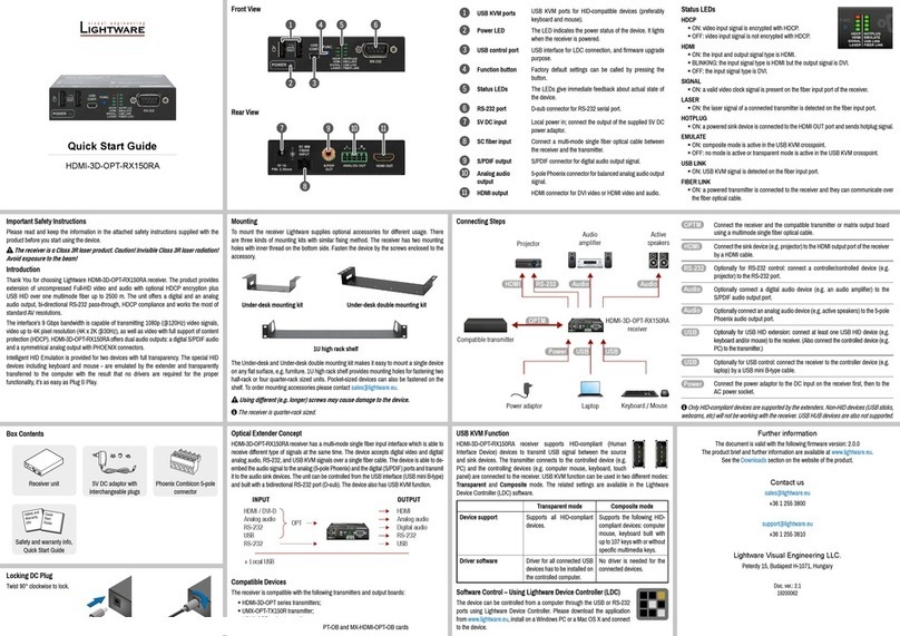
Lightware HDMI-3D-OPT-RX150RA User manual

Lightware
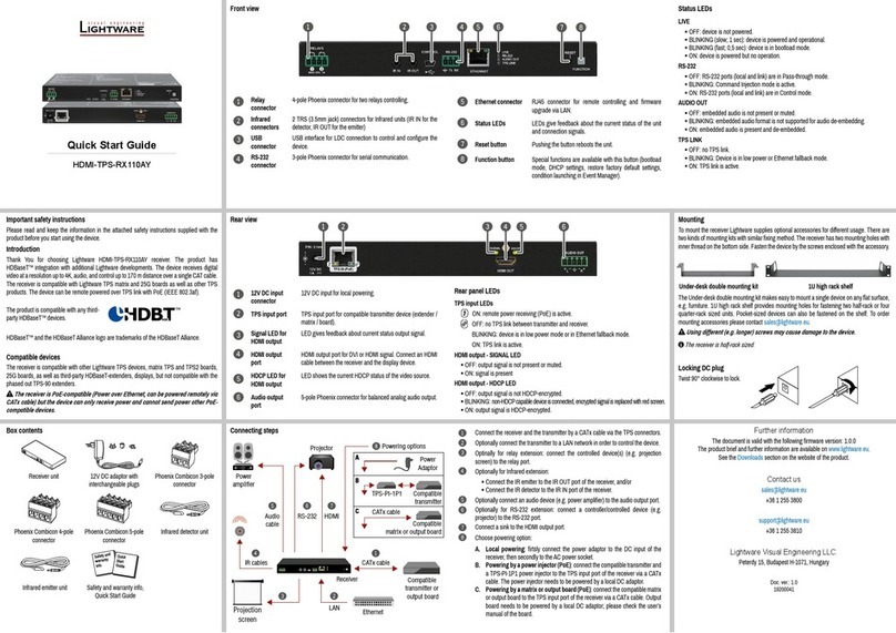
Lightware HDBaseT HDMI-TPS-RX110AY Operating and maintenance instructions

Lightware
Lightware DVI-TP-TX200DL User manual

Lightware
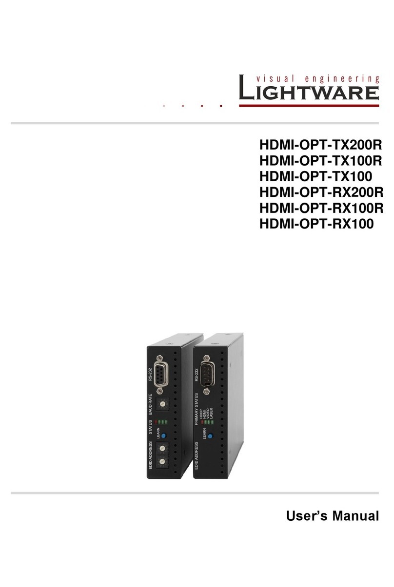
Lightware HDMI-TP-RX200R User manual

Lightware
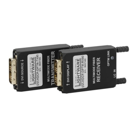
Lightware DVI-HDCP-OPTM-TX90 User manual

Lightware
Lightware HDBaseT HDMI-TPS-RX110AY User manual

Lightware
Lightware HDMI-OPT-TX200R User manual

Lightware
Lightware HDMI-TPS-RX120-HDSR User manual

Lightware
Lightware HDMI-3D-OPT-RX150RA User manual