Software Control – Using Lightware Device Controller (LDC)
The device can be controlled from a computer through the Ethernet, USB,
or RS-232 ports using Lightware Device Controller. Please download the
application from www.lightware.com, install on a Windows PC or a macOS
and connect to the device via the Ethernet port.
The IP address of the unit is static (default): 192.168.0.100., DHCP is disabled.
Set dynamic IP address
1. Keep the Function button pressed for 5 seconds; all front panel LEDs start to blink.
2. Release the button, then press it 3 times quickly. DHCP is now enabled.
Restore Factory Default Settings
1. Keep the Function button pressed for 10 seconds; after 5 seconds front panel LEDs
start to blink but keep the button pressed; the LEDs start to blink faster 5 seconds later.
2. Release the button, then press it 3 times quickly; the following factory default settings
are restored:
IP address (static) 192.168.0.100
Subnet mask 255.255.255.0
Static gateway 192.168.0.1
DHCP Disabled
TCP/IP port nr. LW2 / LW3 10001 / 6107
Input TPS mode Auto
Emulated EDID Dynamic
RS-232 mode Passthrough
RS-232 control protocol LW2
RS-232 port setting 57600 BAUD, 8, N, 1
Command injection port (local / link) 8001 / 8002
Relay connection state Open
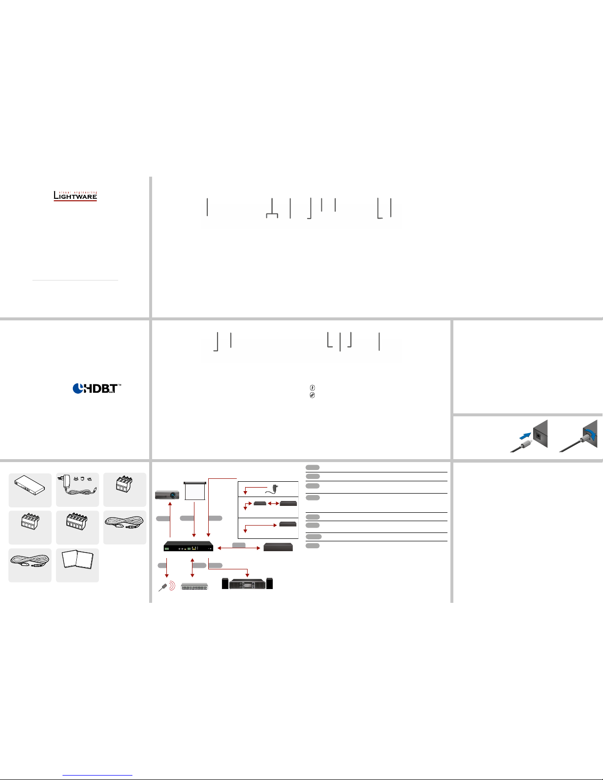
HDMI-TPS-RX110AY
Port Diagram
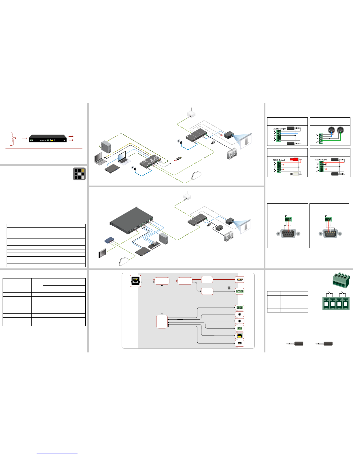
Typical Application
Standalone Application Diagram
TPS Receiver Concept
HDMI-TPS-RX110AY is a multifunctional TPS receiver with audio de-embedding function and
relay extension. The device receives audio/video, Ethernet, RS-232, and Infrared signals via
the TPS input port, and it can be powered by another extender due to the PoE-compatibility.
The receiver can be controlled via USB, Ethernet, RS-232 or Infrared and is able to control
third-party devices via the RS-232, Ethernet, Infrared and relay interfaces.
Types of IR Connectors (1/8” TRS / TS)
2 pole, 1 ring: IR transmitter
3 pole, 2 rings: IR receiver
Relay Connector
HDMI-TPS-RX110AY receiver contains two relays which can be
connected with a 4-pole Phoenix connector. Relays can be controlled
by Lightware protocol commands (LW3) and Event manager actions
can be assigned to the port. Relay connector pin assignment:
Pin nr. Description
1 Pin 1 for Relay 1
2 Pin 2 for Relay 1
3Pin 1 for Relay 2
4 Pin 2 for Relay 2
The device built with normally open (N.O.) contact relays which means when the
unit is not powered (DC plug is disconnected), the relays will open.
The maximum ratings for each relay are 30V and 1A, AC/DC. The default status of the
relays is open.
Maximum Extension Distances
Resolution Pixel
clock rate
Cable lengths
(Auto / Long reach TPS mode)
CAT5e
AWG24
CAT7
AWG26
CAT7
AWG23
1024x768@60Hz 65 MHz 100 m / 130 m* 90 m / 120 m* 120 m / 170 m*
1280x720p@60Hz 73.8 MHz 100 m / 130 m* 90 m / 120 m* 120 m / 170 m*
1920x1080p@60Hz (24bpp) 148.5 MHz 100 m / 130 m* 90 m / 120 m* 120 m / 170 m*
1920x1200@60Hz 152.9 MHz 100 m / NA 90 m / NA 120 m / NA
1600x1200@60Hz 162 MHz 100 m / NA 90 m / NA 120 m / NA
1920x1080@60Hz (36bpp) 223 MHz 70 m / NA 70 m / NA 100 m / NA
3840x2160@30Hz UHD 297 MHz 70 m / NA 70 m / NA 100 m / NA
4096x2160@30Hz 4K 297 MHz 70 m / NA 70 m / NA 100 m / NA
* Long reach TPS mode supports pixel clock frequencies up to 148.5 MHz.
Above values are valid when the transmitter is powered by a local adaptor; distances may decrease
depending on the powering mode (local or remote) and cable quality. To specify the accurate
extension distances, please also check the documentation of the connected TPS device.
CAT7 SFTP AWG23 cable is always recommended.
HDMI out
Analog
audio out
USB
control
RS-232
IR out
Ethernet
TPS in
IR in
Relay
HDBaseT
D/A
converter
Digital video
Analog
audio
Digital
audio
Processor
HDMI
reclocker
Audio
de-embedder
TM
receiver
TPS IN (PoE)
HDMI
HDMI-TPS-RX110AY
UMX-TPS-TX140
RS-232
IR
LAN
LAN
Analog
audio
Volume
control
HDMI
Projector
Active speakers
Wi-Fi access point
Electric
projector
screen
12VDC
1.5A---
_
PIN:2mm
12VDC
1.5A---
_
AUDIOOUT
HDMIOUT
SIGNAL AUDIO
TPSIN(PoE)
TPSReceiver with Relay modules andAudio de-embedding
HHDDMMII--TTPPSS--RRXX111100AAYY
MadeinEU, Hungary
RoHS
Forbestperformance use AWG23
CAT6orCAT7SFTP cable
Devicecanbe remote powered over TPS link with PoE
(IEEE802.3af)
Sn:
FrontLEDs
LIVE
RS-232
Fastblinking(0.5 sec): Firmware upgrade mode
ON:Poweredbut no operation
OFF:Nopower
OFF:Pass-throughmode
Blinking(1sec): Normal operation
Blinking:CommandInjection mode
ON:Controlmode
OFF:NoTPS link
TPSLINK
Blinking:Lowpower mode
ON:TPSlink active
AUDIOOUT
OFF:Embeddedaudio not present or muted
Blinking:Embeddedaudio format not supported
foraudiode-emebedding
ON:Embeddedaudio present and de-embedded
HDCP
Blinking:NonHDCP capable device connected,
encryptedsignalreplaced with red screen
RearLEDs
SIGNAL
ON:Signalpresent
OFF:Outputsignal not present or muted
TPSINPUT
HDMIOUTPUT
OFF:Outputsignal not HDCP encrypted
ON:Outputsignal HDCP encrypted
-Remotepower (PoE)
-TPSLink
IR
emitter
12V DC
Power
adaptor
12V DC
Power
adaptor
Remote
control
PC
MacBook
VGA Laptop
DVI
Media player
TPS
(up to 170 m)
IR detector
VGA
DisplayPort
HDMI
PIN:2.1mm GPIO
RS-232
TXRX
AUDIO2IN
DVI-IIN
IRIN IR OUT
LIVE
RS-232
SRVC
LINK
12V1ADC
TPSOUT(PoE)
ETHERNET
12 3 4 5 6 7 8
PUSHTOEJECT
CD/USB/SD / AUX/BT/FM/AM
EJECT
SD
TEXT
LOCK
ALL/
FOLDER
RANDOM
REPEAT
AUXIN
POWER
USB
CD/USB/SD
AUX/BT STOP PLAY
BTAAC
2 00:03:16
RELAY
Videoconference
codec
PC
Media player
HDMI-TPS-RX110AY
Control System
Ethernet Switch
RS-232
RELAY
LAN
LAN
LAN
LAN
Analog
audio
HDMI Projector
Audio
amplifier
Speakers
Wi-Fi access point
Electric projector screen
12VDC
1.5A---
_
PIN:2mm
12VDC
1.5A---
_
AUDIOOUT
HDMIOUT
SIGNAL AUDIO
TPSIN(PoE)
TPSReceiverwith Relay modules and Audio de-embedding
HHDDMMII--TTPPSS--RRXX111100AAYY
MadeinEU, Hungary
RoHS
Forbestperformance useAWG23
CAT6orCAT7SFTP cable
Devicecanbe remote powered over TPS link with PoE
(IEEE802.3af)
Sn:
FrontLEDs
LIVE
RS-232
Fastblinking(0.5 sec): Firmware upgrade mode
ON:Poweredbut no operation
OFF:Nopower
OFF:Pass-throughmode
Blinking(1sec): Normal operation
Blinking:CommandInjection mode
ON:Controlmode
OFF:NoTPSlink
TPSLINK
Blinking:Lowpower mode
ON:TPSlink active
AUDIOOUT
OFF:Embeddedaudio not present or muted
Blinking:Embeddedaudio format not supported
foraudiode-emebedding
ON:Embeddedaudio present and de-embedded
HDCP
Blinking:NonHDCPcapable device connected,
encryptedsignalreplaced with red screen
RearLEDs
SIGNAL
ON:Signalpresent
OFF:Outputsignal not present or muted
TPSINPUT
HDMIOUTPUT
OFF:Outputsignal not HDCPencrypted
ON:Outputsignal HDCPencrypted
-Remotepower (PoE)
-TPSLink
MMX6×2-HT210
ETHERNET
Volume
control
12 3 4 5 6 7 8
PUSHTOEJECT
CD/USB/SD/AU X / BT / FM / AM
EJECT
SD
TEXT
LOCK
ALL/
FOLDER
RANDOM
REPEAT
AUXIN
POWER
USB
CD/USB/SD
AUX/BT STOP PLAY
BTAAC
200:03:16
TPS
(up to 170 m)
Audio Cable Wiring Guide
The device is built with 5-pole Phoenix connector so we would like to help users assembling
their own audio cables. See the most common cases below.
From balanced output to balanced input
Phoenix - 2x6.3 (1/4”) TRS
From balanced output to balanced input
Phoenix cable - 2x XLR plugs
2
3
2
3