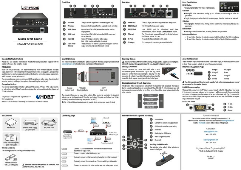
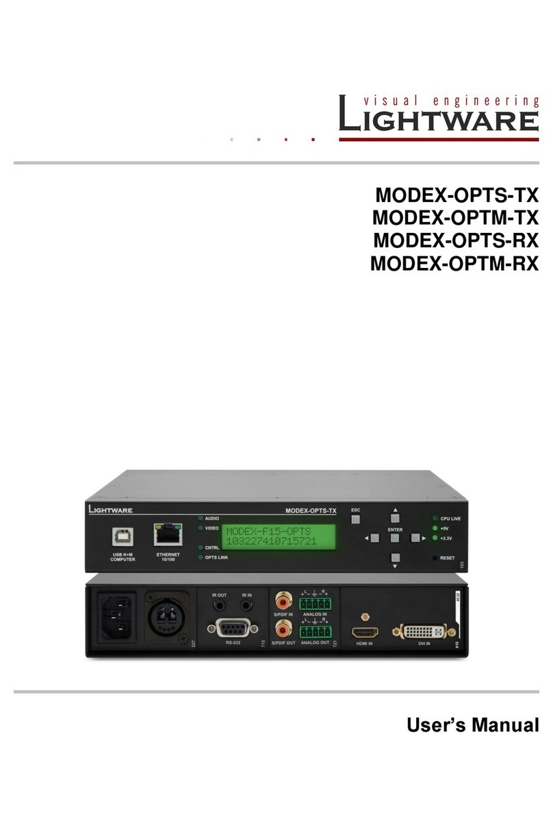
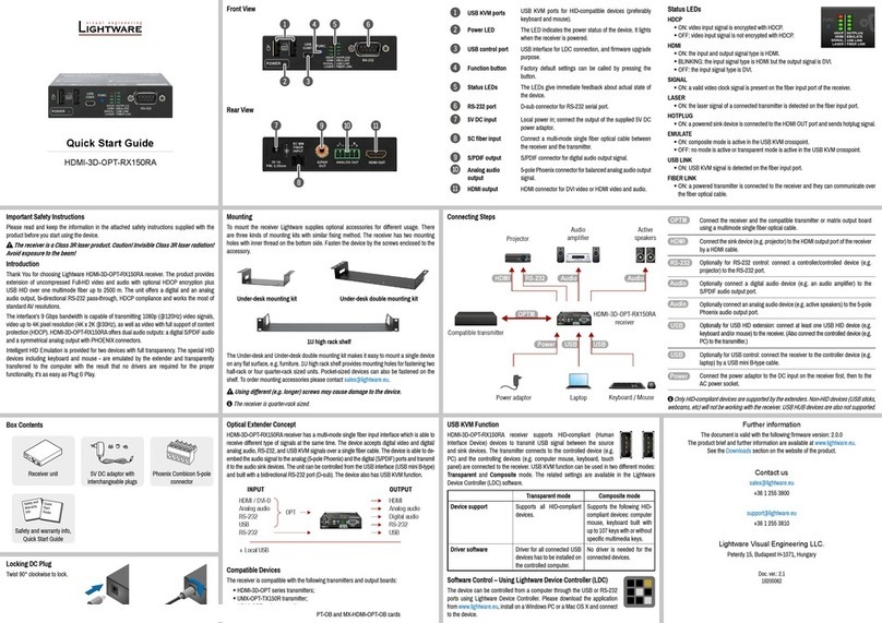
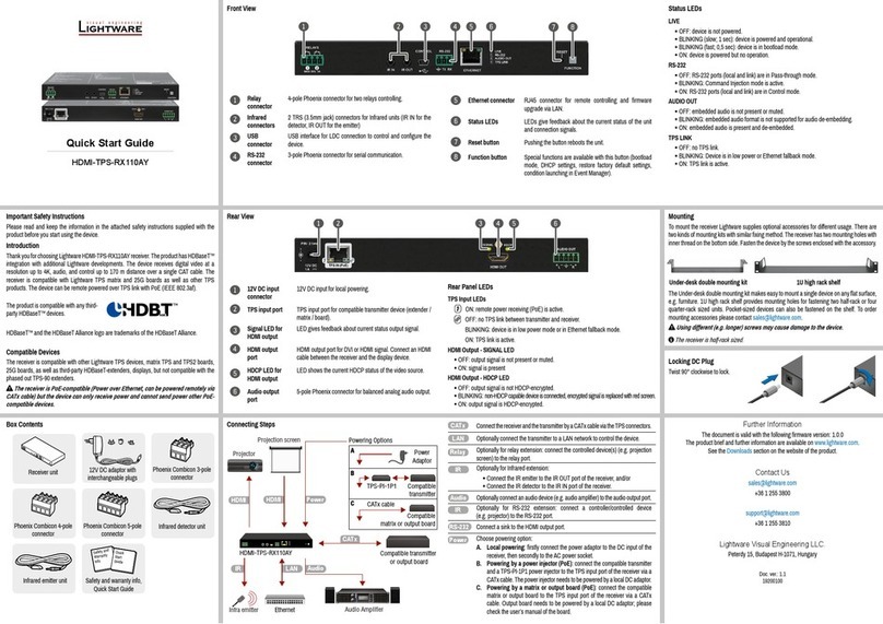
Lightware HDMI-OPT-TX200R User manual

HDMI-OPT-TX200R
HDMI-OPT-TX100R
HDMI-OPT-TX100
HDMI-OPT-RX200R
HDMI-OPT-RX100R
HDMI-OPT-RX100
User’s Manual


HDMI-OPT-TX and RX family
User’s Manual
Page 3 / 60
SAFETY INSTRUCTIONS
Class II apparatus construction.
This equipment should be operated only from the power source indicated on the
product.
To disconnect the equipment safely from power, remove the power cord from the
rear of the equipment, or from the power source. The MAINS plug is used as the
disconnect device, the disconnect device shall remain readily operable.
There are no user-serviceable parts inside of the unit. Removal of the top cover
will expose dangerous voltages. To avoid personal injury, do not remove the top
cover. Do not operate the unit without the cover installed.
The apparatus shall not be exposed to dripping or splashing and that no objects
filled with liquids, such as vases, shall be placed on the apparatus.
The apparatus must be safely connected to multimedia systems. Follow
instructions described in this manual.
WEEE (Waste Electrical & Electronic Equipment)
Correct Disposal of This Product
This marking shown on the product or its literature, indicates that it should
not be disposed with other household wastes at the end of its working life.
To prevent possible harm to the environment or human health from
uncontrolled waste disposal, please separate this from other types of wastes
and recycle it responsibly to promote the sustainable reuse of material
resources.
Household users should contact either the retailer where they purchased this
product, or their local government office, for details of where and how they can take this
item for environmentally safe recycling.
Business users should contact their supplier and check the terms and conditions of the
purchase contract. This product should not be mixed with other commercial wastes for
disposal.

Page 4 / 60
DECLARATION OF CONFORMITY
We,
Lightware Kft. 15 Peterdy Street, Budapest H-1071, HUNGARY
as manufacturer declare, that the products
HDMI-OPT-TX200R
HDMI-OPT-TX100R
HDMI-OPT-TX100
HDMI-OPT-RX200R
HDMI-OPT-RX100R
HDMI-OPT-RX100
(Computer Monitor Extender)
in accordance with the EMC Directive 2004/108/EC and the Low Voltage Directive
2006/95/EEC is in conformity with the following standards:
EMI/EMC..................................... EN 55022 Class B
Safety...........UL, CUL, GS, CR, RCM, PSE, Class II
Date: 12 April 2012
Name: Gergely Vida (Managing Director)
Signed:

HDMI-OPT-TX and RX family
User’s Manual
Page 5 / 60
Table of contents
1. INTRODUCTION....................................................................................................................................... 7
2. GENERAL DESCRIPTION....................................................................................................................... 7
2.1. BOX CONTENTS.................................................................................................................................... 7
2.2. TRANSMITTER FEATURES (HDMI-OPT-TX200R/TX100R/TX100)........................................................ 7
2.3. RECEIVER FEATURES (HDMI-OPT-RX200R/RX100R/RX100)............................................................. 8
2.4. APPLICATIONS ..................................................................................................................................... 8
2.5. UNDERSTANDING EDID...................................................................................................................... 10
2.5.1. Basics ...................................................................................................................................... 10
2.5.2. Common problems related to EDID......................................................................................... 10
2.6. ADVANCED EDID MANAGEMENT......................................................................................................... 11
2.7. PIXEL ACCURATE RECLOCKING........................................................................................................... 11
3. CONTROLS AND CONNECTIONS ....................................................................................................... 13
3.1. HDMI-OPT-TX200R FRONT VIEW...................................................................................................... 13
3.2. HDMI-OPT-TX200R REAR VIEW........................................................................................................ 14
3.3. HDMI-OPT-RX200R FRONT VIEW ..................................................................................................... 15
3.4. HDMI-OPT-RX200R REAR VIEW ....................................................................................................... 15
3.5. HDMI-OPT-TX100R FRONT VIEW...................................................................................................... 16
3.6. HDMI-OPT-TX100R REAR VIEW........................................................................................................ 17
3.7. HDMI-OPT-RX100R FRONT VIEW ..................................................................................................... 18
3.8. HDMI-OPT-RX100R REAR VIEW ....................................................................................................... 18
3.9. HDMI-OPT-TX100 FRONT VIEW ........................................................................................................ 19
3.10. HDMI-OPT-TX100 REAR VIEW ...................................................................................................... 19
3.11. HDMI-OPT-RX100 FRONT VIEW.................................................................................................... 20
3.12. HDMI-OPT-RX100 REAR VIEW...................................................................................................... 20
3.13. ELECTRICAL CONNECTIONS ............................................................................................................ 21
3.13.1. HDMI Inputs and Outputs........................................................................................................ 21
3.13.2. RS-232 connectors.................................................................................................................. 21
4. INSTALLATION AND OPERATION ...................................................................................................... 22
4.1. MOUNTING OF HDMI-OPT UNITS........................................................................................................ 22
4.1.1. Rack shelf................................................................................................................................ 22
4.1.2. Under desk mounting kit.......................................................................................................... 22
4.1.3. Under desk mounting kit double.............................................................................................. 22
4.2. CONNECTING SERIAL DEVICES ............................................................................................................ 23
4.2.1. General information about serial communication.................................................................... 23
4.2.2. Type of serial cables................................................................................................................ 23
4.2.3. Example connection diagrams................................................................................................. 24
4.2.4. Setting up the baud rate (TX200R/TX100R) ........................................................................... 24
4.3. POWERING DEVICES........................................................................................................................... 25
4.3.1. Powering HDMI-OPT extender units ....................................................................................... 25
4.3.2. Boot up of HDMI-OPT extender units...................................................................................... 25
4.4. OPERATION OF HDMI-TX200R/RX200R/RX100RA.......................................................................... 26
4.4.1. Front panel LEDs..................................................................................................................... 26
4.4.2. Learning the EDID (TX200R)................................................................................................... 28
4.4.3. Switching the EDID.................................................................................................................. 28
4.4.4. Factory preset EDID list........................................................................................................... 29
4.5. OUTPUT SETTINGS............................................................................................................................. 30
5. SOFTWARE CONTROL –USING LIGHTWARE MATRIX CONTROLLER......................................... 31
5.1. INSTALLING THE MATRIX CONTROLLER SOFTWARE............................................................................... 31
5.2. ESTABLISHING THE CONNECTION......................................................................................................... 32
5.3. CONTROL MENU................................................................................................................................. 33
5.4. INPUT PROPERTIES (TX200R)............................................................................................................ 34
5.5. EDID MENU (TX200R/TX100R) ........................................................................................................ 34
5.5.1. EDID operation ........................................................................................................................ 34

Page 6 / 60
5.5.2. Advanced EDID Editor............................................................................................................. 36
5.5.3. Make an EDID without YUV colorspace supporting ................................................................ 36
5.5.4. Easy EDID Creator .................................................................................................................. 37
5.6. TERMINAL MENU................................................................................................................................. 37
5.7. STATUS MENU.................................................................................................................................... 38
5.8. FIND MENU ........................................................................................................................................ 38
6. FIRMWARE UPGRADE ......................................................................................................................... 39
7. TROUBLESHOOTING ........................................................................................................................... 43
7.1. GENERAL PROBLEMS.......................................................................................................................... 43
7.2. THERE IS NO PICTURE......................................................................................................................... 43
7.3. PICTURE IS AVAILABLE BUT STRANGE COLORED ................................................................................... 44
8. SPECIFICATIONS.................................................................................................................................. 45
9. MECHANICAL DRAWINGS................................................................................................................... 47
9.1. HDMI-OPT-TX200R......................................................................................................................... 47
9.2. HDMI-OPT-TX100R......................................................................................................................... 49
9.3. HDMI-TP-TX100.............................................................................................................................. 51
9.4. HDMI-OPT-RX200R........................................................................................................................ 53
9.5. HDMI-OPT-RX100R........................................................................................................................ 55
9.6. HDMI-OPT-RX100........................................................................................................................... 57
10. VERSION APPLICABILITY ................................................................................................................ 59
11. WARRANTY........................................................................................................................................ 59
12. DOCUMENT REVISION HISTORY..................................................................................................... 60

HDMI-OPT-TX and RX family
User’s Manual
Section 1. Introduction Page 7 / 60
1. Introduction
Dear Customer,
Thank you for choosing Lightware HDMI-OPT series transmitters and receivers.
HDMI-OPT-TX200R/100R/100 and HDMI-OPT-RX200R/100R/100 are HDMI over
Multimode Fiber Cable extenders which allow deep color video signals of up to
2048x1080@60Hz resolution to be transmitted through 2600 meters of high quality fiber
cables.
2. General description
2.1. Box contents
HDMI-OPT unit (TX200R/TX100R/TX100/RX200R/RX100R/RX100)
User's manual (this document)
Quick Start Guide
+5V wall plug adaptor
2.2. Transmitter features (HDMI-OPT-TX200R/TX100R/TX100)
Supports all HDTV resolutions –720p, 1080i and 1080p etc. with or without HDCP
encoding. Signals with up to 225 MHz pixel clock frequency -
regardless of the resolution - are passed through.
HDCP compliant –The HDMI-OPT extenders support HDCP encrypted HDMI signal
transmission.
Cross compatibility with any Lightware Fiber Optical device –Cross compatibility
between all the devices in the product series is ensured thanks to
Lightware’s attentive design. Any transmitter can be paired with any
receiver without restriction. With Lightware’s hybrid modular matrix
concept, it is even possible to connect an extender box directly to the
matrix router using an MX-HDMI-OPT series input or output board
(MX-HDMI-OPT-IB or MX-HDMI-OPT-OB).
Front panel control –EDID address selection with two decimal rotary switches and
LEARN button are available for Advanced EDID Management. On the
HDMI-OPT-TX200R and TX100R the BAUD RATE rotary switch
allows selecting the appropriate speed of serial communication.
RS-232 control (TX200R and TX100R) - The HDMI-OPT-TX200R and TX100R are
controllable via the Lightware Matrix Controller PC software.
Advanced EDID Management and firmware upgrades are available.
Advanced EDID Management (TX200R and TX100R) –The user can emulate any
EDID on the TX200R/TX100R’s input. TX200R can read out and store
any display device’s EDID (attached to the local HDMI output, called
MONITOR OUT) in 49 internal memory locations. Green and red
EDID status LEDs show whether a valid address is selected.
Pixel Accurate Reclocking –(removes jitter caused by long cables) Each output has
a clean, jitter free signal, eliminating signal instability and distortion
caused by long cables or connector reflections.
Bi-directional RS-232 pass-through (TX200R and TX100R) –AV systems can also
contain serial port controllers and controlled devices. Serial port pass-
through supports any unit that works with standard RS-232.

Page 8 / 60 Section 2. General description
Universal power adaptor –HDMI-OPT transmitters are equipped with a universal
+5V DC power adaptor, which accepts AC voltages from 100 to 240
Volts with 50 or 60 Hz line frequency.
Locking DC connector –Special plug of wall adaptor ensures safe power supply.
This type of connector prevents unwanted extractions.
Rack mounting options –Several mounting methods ensure the universal usage.
Units can be placed into standard racks or under flat surfaces.
2.3. Receiver features (HDMI-OPT-RX200R/RX100R/RX100)
Supports all HDTV resolutions –720p, 1080i and 1080p etc. with or without HDCP
encoding. Signals with up to 225 MHz pixel clock frequency -
regardless of the resolution - are passed through.
HDCP compliant –The HDMI-OPT extenders support HDCP encrypted HDMI signal
transmission.
Cross compatibility with any Lightware Fiber Optical device –Cross compatibility
between all the devices in the product series is ensured thanks to
Lightware’s attentive design. Any transmitter can be paired with any
receiver without restriction. With Lightware’s hybrid modular matrix
concept, it is even possible to connect an extender box directly to the
matrix router using an MX-HDMI-OPT series input or output board
(MX-HDMI-OPT-IB or MX-HDMI-OPT-OB).
Pixel Accurate Reclocking –(removes jitter caused by long cables) Each output has
a clean, jitter free signal, eliminating signal instability and distortion
caused by long cables or connector reflections.
Bi-directional RS-232 pass-through (RX200R and RX100R) –AV systems can also
contain serial port controllers and controlled devices. Serial port pass-
through supports any unit that works with standard RS-232.
Universal power adaptor –HDMI-OPT receiver units are equipped with a universal
+5V power adaptor, which accepts AC voltages from 100 to 240 Volts
with 50 or 60 Hz line frequency.
Locking DC connector –Special plug of wall adaptor ensures safe power supply.
This type of connector prevents unwanted extractions.
Rack mounting options –Several mounting methods ensure the universal usage.
Units can be placed into standard racks or under flat surfaces.
2.4. Applications
Application examples
Long distance lossless HDMI or DVI signal transmission
Ground loop isolation
Multiroom video and audio control
Professional AV systems, conference rooms
High End home cinema
Yacht installations
Info: For the compatible Lightware products please see the compatibility table on the
Lightware homepage.

HDMI-OPT-TX and RX family
User’s Manual
Section 2. General description Page 9 / 60
Figure 2-1. Typical stand-alone application for TX200R and RX200R
Figure 2-2. Typical stand-alone application for TX100R and RX100R
Figure 2-3. Typical stand-alone application for TX100 and RX100
Figure 2-4. Integrated system operation for HDMI-OPT extenders

Page 10 / 60 Section 2. General description
2.5. Understanding EDID
2.5.1. Basics
EDID stands for Extended Display Identification Data. Simply put, EDID is the passport of
display devices (monitors, TV sets, projectors). It contains information about the display’s
capabilities, such as supported resolutions, refresh rates (these are called Detailed
Timings), the type and manufacturer of the display device, etc.
After connecting a HDMI source to a HDMI display, the source reads out the EDID to
determine the resolution and refresh rate of the image to be transmitted.
Figure 2-5. EDID communication
Most DVI computer displays have 128-byte long EDID structure. However, Digital
Televisions and HDMI capable displays may have another 128 bytes, which is called E-
EDID and defined by CEA (Consumer Electronics Association). This extension contains
information about additional Detailed Timings, audio capabilities, speaker allocation and
HDMI capabilities. It is important to know, that all HDMI capable devices must have CEA
extension, but not all devices which have the extension are HDMI capable.
2.5.2. Common problems related to EDID
Problem: „My system consists of the following: a Blu-Ray player, then a Lightware
HDMI-OPT-TX200R, a WUXGA (1920x1200) LCD as local monitor, then a
HDMI-OPT-RX200R connected to an SXGA (1280x1024) projector and an
UXGA (1600x1200) monitor. I would like to see the same image on the
monitors and the projector. What EDID should I chose on the
HDMI-OPT-TX200R?” See typical application in section 2.4.
Solution: If you want to see the image on all three displays, you need to select the
resolution of the smallest display (in this case SXGA), otherwise the smaller
display may not show the higher resolution image.

HDMI-OPT-TX and RX family
User’s Manual
Section 2. General description Page 11 / 60
Problem: „I turned the rotary switches on the HDMI-OPT-TX200R to have a different
resolution but nothing happens.”
Solution: Some graphics cards and video sources read out the EDID only after power-
up and later they don’t sense that EDID has been changed. You need to
restart your source to make it read out the EDID again.
Problem: „I have a HDMI-OPT-TX200R and I’m using a Lightware factory preset EDID. I
would like to be able to choose from different resolutions, but my source
allows only one resolution.”
Solution: Most Lightware factory preset EDIDs allow only one resolution, forcing the
sources to output only that particular signal. You need to select the Universal
EDID (address #49). It supports all common VESA resolutions. Additionally it
also features audio support.
2.6. Advanced EDID Management
Each HDMI sink (e.g. monitors, projectors, plasma displays, and switcher inputs) must
support the EDID data structure. Source BIOS and operating systems are likely to query
the sink using DDC2B protocol to determine what pixel formats and interface are
supported. HDMI standard makes use of EDID data structure for the identification of the
monitor type and capabilities. Most HDMI sources (VGA cards, set top boxes, etc.) will
output HDMI signal after accepting the connected sink’s EDID information. In case of
EDID readout failure or missing EDID the source will not output HDMI video signal.
HDMI-OPT-TX200R and TX100R provide Lightware’s Advanced EDID Management
function that helps system integration.
TX100R stores and emulates 99 EDIDs. TX200R stores and emulates 99 EDIDs plus the
EDIDs of the display devices which connected to local HDMI output, called MONITOR
OUT. Memory addresses #01..#50 are factory presets, while memories #51..#99 are user
programmable in the case of both transmitters.
The EDID emulated on the HDMI input can be copied from the TX200R/TX100R’s
memory (static EDID emulation) or from the last attached monitor (dynamic EDID
emulation) in case of TX200R. For example, the HDMI-OPT-TX200R can be set up to
emulate the device, which is connected to local HDMI output, and the EDID automatically
changes, if the monitor is replaced with another display device (as long as it has a valid
EDID).
Info The user is not required to disconnect the HDMI cable to change an EDID as opposed to
other manufacturer’s products. EDID can be changed even if a source is connected to the
input and it is powered ON.
Info When EDID has been changed, TX200R/TX100R/TX100 toggles the HOTPLUG signal
for 2 seconds. Some sources do not observe this signal, so in this case the change is not
recognized by the source. In such cases the source device must be restarted or powered
OFF and ON again.
2.7. Pixel Accurate Reclocking
Signal reclocking is an essential important procedure in digital signal transmission. After
passing the reclocking circuit, the signal becomes stable and jitter-free, and can be
transmitted over more equipment like processors, or event controllers. Without reclocking,
sparkles, noise and jaggies can be seen on the image.
Lightware’s sophisticated Pixel Accurate Reclocking technology fixes more problems than
general TMDS reclocking. It removes not only intra-pair skew but inter-pair skew as well.
The Pixel Accurate Reclocking circuit eliminates the following errors:

Page 12 / 60 Section 2. General description
Intra-pair skew: skew between the + and - wires within a differential wire pair (e.g.
Data2- and Data2+). It’s caused by different wire lengths or slightly
different wire construction (impedance mismatch) in HDMI cable. It
results in jitter.
Inter-pair skew: skew between two differential wire pairs in a cable. It’s caused by
different wire pair lengths or different number of twists in the HDMI
cable. Too much inter-pair skew results in color shift in the picture or
sync loss.
Jitter: signal instability in the time domain. The time difference between two
signal transitions should be a fixed value, but noise and other effects
cause variations.
Noise: electromagnetic interference between other electronic devices such as
mobile phones, motors, etc. and the HDMI cable are coupled onto the
signal. Too much noise results in increased jitter.
The Pixel Accurate Reclocking circuit completely regenerates the original video signal
and outputs a strong, high-quality digital signal that conforms to the HDMI specification.

HDMI-OPT-TX and RX family
User’s Manual
Section 3. Controls and connections Page 13 / 60
3. Controls and connections
3.1. HDMI-OPT-TX200R front view
Figure 3-1. Front view
Status LEDs The LEDs give feedback about the state of units and video
signal. For more information about names and meanings of the
Status LEDs see chapter 4.4.1.
LEARN button Stores the EDID of the display device attached to local HDMI
output, called MONITOR OUT in the selected memory address
between #51..#99. To learn the EDID, select an appropriate
address with the rotary switches and press and hold the Learn
button for two seconds. For more information see chapter 4.4.2.
Toggles the LED functions between PRIMARY (SOLID) and
SECONDARY (BLINKING). For more information see chapter
4.4.1.
RS-232 Port 9-pole D-sub female connector. Connect a serial cable between
the transmitter unit and the desired serial device. See sections
3.13.2 and 4.2 for more information about usage of serial port.
Rotary switches The rotary switches select one of 99 addresses. EDID
memories #1..#50 contain factory presets and #51..#99 are
user programmable. Address #00 enables dynamic EDID
emulation which copies EDID from local HDMI output, called
MONITOR OUT. For more information, see chapter 4.4.3.
Baud Rate Rotary The rotary switch selects one of 5 speeds of the serial
communication (#0..#4) or the Software Control mode (#9). For
more information see chapter 4.2.4.
Info: Use a flat head screwdriver that fits into the rotary switches’ actuator. Avoid the use of
keys, coins, knives and other sharp objects because they might cause permanent
damage to the rotary switches.
Baud Rate Rotary
4
RS-232 Port
1
LEARN button
2
EDID ADDR. Rotary
4
STATUS LEDs
1
3
4
5
1
2

Page 14 / 60 Section 3. Controls and connections
3.2. HDMI-OPT-TX200R rear view
Figure 3-2. Rear view
HDMI INPUT Connect one HDMI cable between the HDMI source and the
transmitter unit. For more information see chapter 3.13.1.
MONITOR OUT Connect one HDMI cable between the local display device and
the transmitter unit. For more information see chapter 3.13.1.
SC Fiber Output Connect a multimode single fiber optical cable between the
transmitter unit and the receiver unit (or a Lightware Hybrid
Modular Matrix equipped with optical input card).
DC +5V in Connect the output of the supplied +5V DC power adaptor.
CAUTION! Warranty void if damage occurs due to use of a
different power source. For more information see chapter 4.3.
DC +5V in
4
0
MONITOR OUT
2
SC Fiber Output
3
HDMI INPUT
1
2
1
3
4

HDMI-OPT-TX and RX family
User’s Manual
Section 3. Controls and connections Page 15 / 60
3.3. HDMI-OPT-RX200R front view
Figure 3-1. Front view
Status LEDs The LEDs give feedback about the state of units and video
signal. For more information about names and meanings of the
Status LEDs see chapter 4.4.1.
RS-232 Port 9-pole D-sub male connector. Connect a serial cable between
the receiver unit and the desired serial device. See sections
3.13.2 and 4.2 for more information about usage of serial port.
Function Button Toggles the LED functions between PRIMARY (SOLID) and
SECONDARY (BLINKING). For more information see chapter
4.4.1.
3.4. HDMI-OPT-RX200R rear view
Figure 3-2. Rear view
HDMI OUT 1 Connect one HDMI cable between the receiver and the first
display device. For more information see chapter 3.13.1.
HDMI OUT 2 Connect one HDMI cable between the receiver and the second
display device. For more information see chapter 3.13.1.
SC Fiber Input Connect a multimode single fiber optical cable between the
receiver and the transmitter (or a Lightware Hybrid Modular
Matrix equipped with optical output card).
DC +5V in Connect the output of the supplied +5V DC power adaptor.
CAUTION! Warranty void if damage occurs due to use of a
different power source. For more information see chapter 4.3.
Function Button
4
RS-232 Port
1
STATUS LEDs
2
HDMI OUT 1
1
HDMI OUT 2
2
DC +5V in
4
SC Fiber Input
3
2
3
1
1
4
2
3

Page 16 / 60 Section 3. Controls and connections
3.5. HDMI-OPT-TX100R front view
Figure 3-3. Front view
Status LEDs The LEDs give feedback about the state of units and video
signal. For more information about names and meanings of the
Status LEDs see chapter 4.4.1.
LEARN button Toggles the LED functions between PRIMARY (SOLID) and
SECONDARY (BLINKING). For more information see chapter
4.4.1.
RS-232 Port 9-pole D-sub female connector. Connect a serial cable between
the transmitter unit and the desired serial device. See sections
3.13.2 and 4.2 for more information about usage of serial port.
Rotary switches The rotary switches select one of 99 addresses. EDID
memories #1..#50 contain factory presets and #51..#99 are
user programmable. For more information, see chapter 4.4.3.
Baud Rate Rotary The rotary switch selects one of 5 speeds of the serial
communication (#0..#4) or the Software Control mode (#9). For
more information see chapter 4.2.4.
Info: Use a flat head screwdriver that fits into the rotary switches’ actuator. Avoid the use of
keys, coins, knives and other sharp objects because they might cause permanent
damage to the rotary switches.
Baud Rate Rotary
4
RS-232 Port
1
LEARN Button
2
EDID ADDR. Rotary
4
STATUS LEDs
1
4
1
5
2
3

HDMI-OPT-TX and RX family
User’s Manual
Section 3. Controls and connections Page 17 / 60
3.6. HDMI-OPT-TX100R rear view
Figure 3-4. Rear view
HDMI INPUT Connect one HDMI cable between the HDMI source and the
transmitter unit. For more information see chapter 3.13.1.
SC Fiber Output Connect a multimode single fiber optical cable between the
transmitter unit and the receiver unit (or a Lightware Hybrid
Modular Matrix equipped with optical input card).
DC +5V in Connect the output of the supplied +5V DC power adaptor.
CAUTION! Warranty void if damage occurs due to use of a
different power source. For more information see chapter 4.3.
DC +5V in
3
SC Fiber Output
2
HDMI INPUT
1
2
3
1

Page 18 / 60 Section 3. Controls and connections
3.7. HDMI-OPT-RX100R front view
Figure 3-5. Front view
Status LEDs The LEDs give feedback about the state of units and video
signal. For more information about names and meanings of the
Status LEDs see chapter 4.4.1.
RS-232 Port 9-pole D-sub male connector. Connect a serial cable between
the transmitter unit and the desired serial device. See sections
3.13.2 and 4.2 for more information about usage of serial port.
3.8. HDMI-OPT-RX100R rear view
Figure 3-6. Rear view
HDMI OUT Connect one HDMI cable between the receiver unit and the
display device. For more information see chapter 3.13.1.
SC Fiber Input Connect a multimode single fiber optical cable between the
receiver unit and the transmitter unit (or a Lightware Hybrid
Modular Matrix equipped with optical output card).
DC +5V in Connect the output of the supplied +5V DC power adaptor.
CAUTION! Warranty void if damage occurs due to use of a
different power source. For more information see chapter 4.3.
Status LEDs
1
RS-232 Port
2
SC Fiber Input
2
HDMI OUTPUT
1
DC +5V in
3
2
1
2
3
1

HDMI-OPT-TX and RX family
User’s Manual
Section 3. Controls and connections Page 19 / 60
3.9. HDMI-OPT-TX100 front view
Figure 3-7. Front view
Status LEDs The LEDs give feedback about the state of units and video
signal. For more information about names and meanings of the
Status LEDs see chapter 4.4.1.
LEARN button Toggles the LED functions between PRIMARY (SOLID) and
SECONDARY (BLINKING). For more information see chapter
4.4.1.
Rotary switches The rotary switches select one of 99 addresses. EDID
memories #1..#50 contain factory presets and #51..#99 are
user programmable. For more information, see chapter 4.4.3.
Info: Use a flat head screwdriver that fits into the rotary switches’ actuator. Avoid the use of
keys, coins, knives and other sharp objects because they might cause permanent
damage to the rotary switches.
3.10. HDMI-OPT-TX100 rear view
Figure 3-8. Rear view
HDMI INPUT Connect one HDMI cable between the HDMI source and the
transmitter unit. For more information see chapter 3.13.1.
SC Fiber Output Connect a multimode single fiber optical cable between the
transmitter unit and the receiver unit (or a Lightware Hybrid
Modular Matrix equipped with optical input card).
DC +5V in Connect the output of the supplied +5V DC power adaptor.
CAUTION! Warranty void if damage occurs due to use of a
different power source. For more information see chapter 4.3.
STATUS LEDs
2
EDID ADDR. Rotary
3
LEARN button
1
DC +5V in
3
SC Fiber Output
2
HDMI INPUT
1
2
1
2
3
1
3

Page 20 / 60 Section 3. Controls and connections
3.11. HDMI-OPT-RX100 front view
Figure 3-9. Front view
Status LEDs The LEDs give feedback about the state of units and video
signal. For more information about names and meanings of the
Status LEDs see chapter 4.4.1.
3.12. HDMI-OPT-RX100 rear view
Figure 3-10. Rear view
HDMI OUT Connect one HDMI cable between the receiver unit and the
display device. For more information see chapter 3.13.1.
SC Fiber Input Connect a multimode single fiber optical cable between the
receiver unit and the transmitter unit (or a Lightware Hybrid
Modular Matrix equipped with optical output card)
DC +5V in Connect the output of the supplied +5V DC power adaptor.
CAUTION! Warranty void if damage occurs due to use of a
different power source. For more information see chapter 4.3.
Status LEDs
1
SC Fiber Input
2
HDMI OUT
1
DC +5V in
3
1
1
2
3
This manual suits for next models
5
Table of contents
Other Lightware Receiver manuals

Lightware
Lightware DVI-TP-TX200DL User manual

Lightware
Lightware HDBaseT HDMI-TPS-RX110AY User manual

Lightware
Lightware MODEX-OPTS-TX User manual

Lightware
Lightware HDMI-TPS-RX120-HDSR User manual

Lightware
Lightware HDBaseT HDMI-TPS-RX110AY Operating and maintenance instructions

Lightware
Lightware HDMI-3D-OPT-RX150RA User manual

Lightware
Lightware DVI-HDCP-OPTM-TX90 User manual

Lightware
Lightware HDMI-TP-RX200R User manual

Lightware
Lightware HDMI-3D-OPT-RX150RA User manual