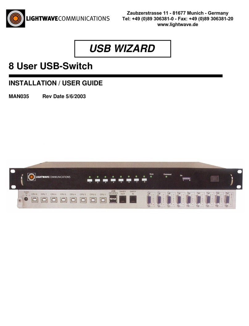
Lightwave Communications System Console Switch User manual

Flow Control User Manual
100 Washington Street, Milford, CT 06460 lTel: 203-878-9838 lFax: 203-874-0157

SystemConsoleSwitch User Manual
1
Table of Contents Page
1.0 Product Description ......................................................................................................3
2.0 System Overview...........................................................................................................4
2.1 Connect up to twelve RS-232C compatible ports..................................................4
2.2 Buffered Data Storage..........................................................................................4
2.3 Direct and Remote Access ...................................................................................4
2.4 Security Password ...............................................................................................4
2.5 Configurable Modem/Auxiliary Port......................................................................4
2.6 Parallel Printer.....................................................................................................4
3.0 System Components......................................................................................................5
3.1 Chassis................................................................................................................5
3.2 Spooler Modules..................................................................................................5
3.3 External Power Supply .........................................................................................5
3.4 System Cable Requirements ................................................................................5
4.0 Installation Instructions ................................................................................................7
4.1 SystemConsoleSwitch Installation........................................................................7
4.2 Daisy-Chaining SystemConsoleSwitches...............................................................18
5.0 The Help Menu..............................................................................................................20
5.1 Using the Help Menu............................................................................................20
5.2 Using Channel Commands ...................................................................................20
5.3 Using Scan Commands........................................................................................22
5.4 Using the Printer Commands...............................................................................24
5.5 Using the Direct Mode Command.........................................................................25
5.6 Name Servers ......................................................................................................26
5.7 Other Useful Commands......................................................................................27
6.0 The Set-Up Menu...........................................................................................................28
6.1 Using the Set-Up Menu ........................................................................................28
6.1.a Set-Up Menu Reference List..............................................................................28
7.0 Remote Access..............................................................................................................32
7.1 Using Remote Access...........................................................................................32
7.1.a Remote Access Configurations ...................................................................32
Modem Initialization.................................................................................32
Modem Hang-Up String............................................................................32
System Connection/Remote Access Password..........................................32
Remote Break-In.......................................................................................33
Modem Privacy.........................................................................................34
8.0 Technical Support and Warranty Information.................................................................35
Appendix A-Component Part Numbers............................................................................... A-i
Appendix B -Trouble Shooting............................................................................................. B-i
Appendix C -Rack Mount SystemConsoleSwitch.................................................................. C-i
Appendix D -Flow Control.................................................................................................... D-i

SystemConsoleSwitch User Manual
2
SystemConsoleSwitch User Manual
11/14/97
Copyright 1995 by Lightwave Communications, Inc.
261 Pepe's Farm Road, Milford, Connecticut, 06460, U.S.A.
All rights reserved. No part of this copyrighted material may be reproduced in any form or by any means without
prior written permission from Lightwave Communication, Inc.
Printed in U.S.A.
For more up-to-date information on the SystemConsoleSwitch and
other Lightwave products, visit us on the web:
www.lightwavecom.com

SystemConsoleSwitch User Manual
3
1.0 Product Description
The SystemConsoleSwitch (SCS) allows a user to control and monitor a maximum of 120
devices from a single terminal. Extensive port buffering facilitates trouble shooting by allowing
the user to scroll back and forth through 30* screens (32 Kbytes) of data per port. The remote
access feature allows a user to connect to the SCS and monitor systems from an off-site
location. Password protection ensures access security.
1.1 Features
lConnect up to twelve RS-232C compatible ports
lDaisy-chained units allow connection of up to 120 devices
l30 Screens of Buffered Data Storage per Device
lRemote Access via Modem Port
lSecurity Password
lConfigurable Modem/Auxiliary Port
lParallel Printer Port
* The number of data screens will vary, depending on the data displayed.

SystemConsoleSwitch User Manual
4
2.0 System Overview
2.1 Connect up to twelve RS-232C compatible ports
The SystemConsoleSwitch (SCS) is plug compatible with any RS-232 device. Daisy-
chained SystemConsoleSwitches can control up to 120 terminal ports (maximum
recommended). These may be a variety of network servers, routers, and any other
LAN/WAN computers on the network. Access to any one of the connected ports is
achieved through simple keyboard commands (channel selection) through the attached
terminal.
2.2 Buffered Data Storage
Dual Spooler modules allow storage of up to 30 screens (32 Kbytes) of data per device.
Each dual spooler module contains circuitry to support two totally independent devices.
Data storage is continuous for all connected devices. Each SCS is expandable to
accommodate up to six dual spooler modules, allowing 12 devices to be connected.
2.3 Direct and Remote Access
There are two means of access for the SystemConsoleSwitch. One method of access is
through a terminal that is directly connected to the SCS. The alternate method is to use a
dial-up modem from a remote site. Both means of access gives the user the capability to
monitor activity from any connected device, and to interact with each device directly.
2.4 Security Password
The remote access feature requires a password to complete the connection to the SCS.
Should the user fail on their third attempt to enter a password, the SCS will automatically
disconnect the user.
2.5 Configurable Modem/Auxiliary Port
The built in modem port may also be configured to function as an auxiliary terminal port.
This features allows the user to have two consoles (terminals) in different locations.
Switches for the Modem/Aux port may be changed while the power is on, without
interruption to the unit.
2.6 Parallel Printer Port
Another significant feature of the SystemConsoleSwitch is the printer port. The user may
select any portion of the stored data and obtain a hard copy from a printer connected to
the printer port.

SystemConsoleSwitch User Manual
5
3.0 System Components
Each SystemConsoleSwitch consists of three major components, the chassis, spooler
modules and the external power supply.
3.1 Chassis
The chassis contains two circuit boards; the Master Circuit Board and the Switch Board.
Dip switches on the master board allow the SCS to be configured at various baud rates
for the terminal and modem ports (refer to section 4.1, step 2 for detailed instructions).
The Switch Board's main function is device selection, and has no user adjustment. The
chassis is equipped with slots to house up to six dual spooler modules.
3.2 Spooler Modules
Each spooler module contains circuitry to support two totally independent ports. There
are two sets of dip switches on the spooler module for baud rate selection of the
attached device. Each set of dip switches are independently set to be compatible with
its corresponding device. Additionally, dip switches are provided on the spooler module
to select the number of data bits per byte, the number of stop bits, and parity (refer to
section 4.1, step 3 for detailed instructions). It should be noted that each of the dual ports
on the spooler module function independently, both in terms of memory and
communication.
3.3 External Power Supply
Power is supplied to the SCS through a +5V DC power supply, which is plugged into a
grounded 100-250 volt AC outlet.
3.3 System Cable Requirements
Device connections are made with the RJ45 connectors on the rear panel and DB25
male/female as well as DB9 male/female adapters for user equipment.
Figure 1 -SCS Cable Assemblies

SystemConsoleSwitch User Manual
6
This connector style is common to a variety of network cabling schemes and may be
purchased from Lightwave Communications Inc. Refer to Appendix A for cable part
numbers. The following cables connect the terminal, printer, modem, auxiliary and CPU
ports:
lSystemConsoleSwitch to Terminal: Use a straight 1:1 DB25 to DB25 cable (P/N
200.0126, supplied with unit -15' included, contact your representative if a different
length is needed).
lSystemConsoleSwitch Parallel Port to Parallel Printer: Use a parallel printer
cable.
lSystemConsoleSwitch Modem Port to Modem: 1:1 modem cable.
lSystemConsoleSwitch Modem Port to Terminal: Null modem cable.
lSystemConsoleSwitch CPU Ports to CPU: Cabling is RJ45. DB25 and DB9 to
RJ45 adapters are available for device connection.
NOTE: Local Area Network (LAN) cables may be used with the SystemConsoleSwitch
because they are pinned straight through (1:1). Do not use Telephony RJ45 Cables as
they have crossed pinouts and damage to the attached devices or the
SystemConsoleSwitch may occur.

SystemConsoleSwitch User Manual
7
4.0 Installation Instructions
Use the following procedure to install a single SystemConsoleSwitch.
4.1 SystemConsoleSwitch Installation
Refer to Appendix A for Rack Mount SystemConsoleSwitch Diagrams
Step 1: Identify the following items in the shipping container (see figure 2)
lSystemConsoleSwitch Chassis (stand-alone or rack-mount)
lAC power cord
l+5V DC power supply
lPower Supply Cord Retainer Clamp (located on DC power cord)
lDB9 serial cable for cascading the SCS
Important: Before beginning the installation procedure, re-seat the master board,
Switch Board and each spooler module board, as shipping may
dislodge them.
Figure 2 -DC Power Supply and DB9 Serial Cable

SystemConsoleSwitch User Manual
8
Figure 3 -Master Board Baud Rate Settings

SystemConsoleSwitch User Manual
9
Figure 3a -Master Board Showing Front Panel LED Indicator Attachment

SystemConsoleSwitch User Manual
10
O
F
F
/ROCKER DOWN
1 2 3 4 56 7 8
LIGHTWAVE COMMUNICATIONS, INC
SYSTEM CONSOLE SWITCH
DUAL PORT SPOOLER MODULE
flow control
stop bits
data bits
parity
baud rate
SW2 - even numbered ports
SW1 - odd numbered ports
The switch positions below produce
the default communication settings for
the CPU ports (9600 baud, no parity, 8
data bits, 1 stop bit):
1 - off
2 - on
3 - off
4 - on
5 - on
6 - off
7 - on
8 - on
Figure 4 - Spooler Module DIP Switch Locations
(spooler card revision D)
The DIP switches on the previous versions of the spooler card were rotated 180 degrees. Position
one was on the left with on towards the connector and off towards the edge handle.

SystemConsoleSwitch User Manual
11
Figure 4a -Spooler Module Dip Switch Settings
ON
ON
ON
ON
ON
ON
ON
ON
ON
ON
ON
ON
ON
ON
ON
ON

SystemConsoleSwitch User Manual
12
Step 2: Master Board Dip Switch Settings The terminal connected to the terminal port
must be a dumb terminal. Some emulation examples are a VT100 or WY60.
If the factory default settings are used, then steps a, b, c below may be
skipped. The default settings are shown in figure 3.
a) Set terminal baud rate
Dip Switches 7 and 8 set the terminal baud rate from 2400 baud to
19.2K baud. The default baud rate settings are: 19.2K baud, no
parity, 8 data bits, and 1 stop bit. Setting the baud rate on the terminal
to match the factory defaults is the best approach. To reset these
switches at a rate other than the factory default setting, first remove
the top section of the front panel, or on Rack Mount units remove the
smoked glass cover. Once the top plate has been removed, the dip
switches are visible. The switches are numbered from left to right, 1-8,
or bottom to top on Rack Mount units. Dip switch 6 selects either X0N/XOFF
or RTS/CTS flow control. The factory default is X0N/XOFF (refer to figure 3)
Note: The power LED indicator is attached to the top section of the
front panel. After completing the baud rate selection, re-connect the
black lead on the power LED indicator to the right-hand side of the two
pin connector on the Master Board (refer to figure 3a).
b) Set Modem/Aux Port Mode
Determine whether the Modem/Aux Port is to be used with a modem or
as an auxiliary port. Dip switch 1 sets this feature. When switch 1 is
in the on position, the port is configured to operate with a modem.
When switch 1 is in the off position, the port is configured to operate
with a terminal (refer to figure 3).
c) Set Modem/Aux port Baud Rate
After determining whether the port is to be used with a modem or a
terminal, set the baud rate for the connected device. Dip switches
4 and 5 set the baud rates from 2400 baud to 19.2K baud (refer to
figure 3). Dip switch 3 selects either X0N/XOFF or RTS/CTS Flow Control.
Factory default is X0N/XOFF.
Note: When in the aux or modem mode, it is not necessary to have
the terminal and the auxiliary port baud rates set the same.
d) After completing steps a, b, and c above, replace the top plate cover
on stand-alone units, or smoked glass cover on Rack Mount units.
Remember on stand-alone units to connect the front panel power

SystemConsoleSwitch User Manual
13
indicator LED with the black wire to the right-hand side of the two pin
connector (refer to figure 3a).
Step 3: Spooler Module Installation
The spooler modules (see figure 5) are installed in the chassis at the factory,
with the default baud rate settings of: 9600 baud, no parity, 8 data bits and 1
stop bit, with XON/XOFF Flow Control. If this setting is compatible with the
attached device, this section may be skipped.
Figure 5 -Spooler Module
a) Remove the lower front panel of the chassis by loosening the two
thumb screw fasteners located at the base of the SCS. On Rack Mount
Units, remove the smoked glass cover. Gently remove
the spooler cards by grasping the handle and pulling straight out.
b) Set dip switches (SW1 and SW2) for the desired baud rate of the
attached device (refer to figure 4). Dip switches 1 and 2 on SW1 and
SW2 correspond to baud rate settings. Dip switches 3, 4, and 5 cor-
respond to the parity of the attached devices. Dip switch 6 is for seven
or eight data bits/bytes. Dip switch 7 is for the number of stop bits.
Dip switch 8 is for Flow Control. Factory default is XON/XOFF Flow Control.
Figures 4 and 4a show the location and definition of the switches. It is
important to make note of the settings of the spooler modules prior to
attaching devices to the SCS. This will ensure that each device is attached to
the proper channel with the correct settings.
c) After the spooler modules are configured, they can be installed in the
chassis.
It is not necessary to turn off power when installing spooler modules.
To re-install the modules, locate the first available set of card guides (slots)
below the switch board module (see figure 6). On Rack Mount Units,

SystemConsoleSwitch User Manual
14
locate the first available set of card guides (slots) to the right of the switch
board module (see figure 6a). It should be noted that the last set of slots in
the chassis (stand-alone units only) are not used. Slide the module,
component side up and connector first, into the card guides. Components
should face the Master Board. Be sure the connector is seated completely
into the chassis connector. Repeat this procedure to re-install all of your
spooler modules (the maximum number of spooler modules per chassis is
six).
Step 4: Connecting devices to the SCS
a) After configuring the master board module and all of the spooler
Figure 6 -SCS with front cover remove
modules for the proper settings, connect the devices to the
spooler modules. Having noted the settings of each channel for the
appropriate spooler modules, the devices are ready to be connected.
Refer to figure 7 and Appendix A for further details regarding proper
pinouts for connection.
b) Connect the terminal to the SCS using a 1:1 DB25 cable (P/N 200.0126,
supplied with unit).

SystemConsoleSwitch User Manual
15
Figure 6a -Rack Mount SCS with smoked glass cover removed
c) Connect the parallel printer to the SCS using a standard printer cable
(see Appendix A).
d) Connect the Modem to the SCS using a modem cable. If an auxiliary
terminal is used on this port, use a null modem cable (See Appendix A).
Step 5: Connecting Power
a) Attach DC power supply cord to SCS with retainer clamp. If the re-
tainer clamp is not already attached to the cord, spread the retainer
clamp and insert the cord through the clamp, then insert retainer
clamp into the hole next to the DC Power Plug connector (see
figure 8).

SystemConsoleSwitch User Manual
16
Figure 7 -SCS Connector Pinouts

SystemConsoleSwitch User Manual
17
b) Attach DC power supply to SCS (refer to figure 8)
Figure 8 -SCS Back Showing Green LEDs and Attached DC Power Cord
c) Plug AC cord into a properly grounded 100-250 volt AC outlet
and the green LED on the top front panel will light (see figure 9).
Figure 9 -SCS Front Showing Green LED

SystemConsoleSwitch User Manual
18
d) Check the rear panel of the SystemConsoleSwitch to be certain
the Spooler Modules are installed correctly. The rear panel LEDs
should be on when spooler modules are installed. With the lower
front cover removed, verify that all of the green LED's on the
spooler modules are flashing. If any green LED's are not flashing,
re-seat the spooler card with the power on (refer to figure 6).
e) Replace both top and bottom sections of the front panel.
4.2 Daisy-Chaining SystemConsoleSwitches
Step 1: Connect the control in/out ports of the SystemConsoleSwitches
(see figure 10):
Figure 10 -Daisy-chained SystemConsoleSwitches
a. Using the cable provided, connect the Master "CONTROL OUT"
port to the "CONTROL IN" port of Slave 1.
b. Using another DB9 serial cable connect the "CONTROL OUT"
port of Slave 1 to the "CONTROL IN" port of Slave 2.

SystemConsoleSwitch User Manual
19
c. Follow this procedure until all of the SystemConsoleSwitches
are connected.
The first SCS (connected to the terminal) is referred to as the
Master SCS. All of the SystemConsoleSwitches connected to it
are referred to as "slaves". (see figure 10).
NOTE: Do NOT attach terminal or modem into the slave port,
as erratic behavior will occur.
Step 2: Configure the Slave(s)
From the terminal type C ↵↵. The display will read:
Please wait configuring slaves
Slave 1 configured
Slave 2 configured
" "
" "
" "
" "
Slave 9 configured
NOTE: If the message prompt Slave 1 not found appears, execute the C
↵↵ command again.
The display will always show the message Slave n not found
(where n = next slave number) on the last line of the display, when
less than 9 slaves are connected. The purpose of this message is to
indicate to the user, that the next slave is nonexistent (there are no
more installed slaves at this point).
Table of contents
Other Lightwave Communications Switch manuals

Lightwave Communications
Lightwave Communications USB SuperSwitch User manual

Lightwave Communications
Lightwave Communications ServerSwitch 8200 User manual

Lightwave Communications
Lightwave Communications serverswitch 2X16 User manual

Lightwave Communications
Lightwave Communications USB-Wizard Operation manual
Popular Switch manuals by other brands

Potter
Potter PS120 Series manual

Keysight
Keysight L7104A Operating and service manual

NETGEAR
NETGEAR GS724TS - ProSafe 24 Port Gigabit Stackable Smart... installation guide

Intermatic
Intermatic EI500 Series Installation and user instructions

Automationdirect.com
Automationdirect.com Stride SE3 Series user manual

Transition Networks
Transition Networks SM8TAT2SA install guide