manuals.online logo
Brands
  1. Home
  2. •
  3. Brands
  4. •
  5. Lightwave
  6. •
  7. Switch
  8. •
  9. Lightwave L92 User manual

Lightwave L92 User manual

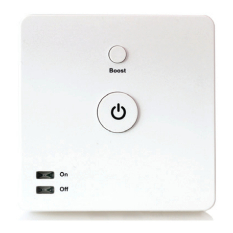
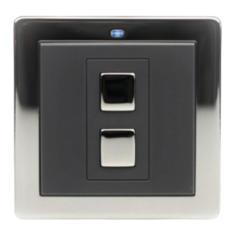
Smart Switch (L92)
Applications
The Smart Switch is designed to switch a load of
up to 3 W (max) manually at the switch
or remotely using the Lightwave App.
The Switch has a built-in temperature sensor.
This allows it to operate automatically based
on changes in local temperature and ideal for
use as a room thermostat operating electric
(panel) heaters. It can also be used to remotely
operate a gas boiler and AC units.
Loading
The max load should not exceed 3 W (16A).
Location
The Smart Switch is a Class II device that does
not require a separate housing. It should only be
installed and used indoors.
If the Smart Switch is to be utilised as a
thermostat, for optimum temperature
monitoring the Internal Temperature Sensor
(located behind the grille on the right side of the
Switch) should not be positioned adjacent to a
direct heat source.
If the Switch is used to control a panel heater,
it should ideally be positioned either below or
adjacent to the bottom corner of the panel
heater at a distance greater than 150mm (6”).
Where it is not possible to isolate the Switch
from direct heat sources, it can be operated in
conjunction with a separate thermostat.
Installation
If you plan to install this product yourself, please
follow the electrical wiring instructions carefully
to ensure the product is installed safely, if in any
doubt please consult a qualified electrician.
It is important to install this product in
accordance with these instructions. Failure to do
so may risk personal safety, create a fire hazard,
violate the law and will also void your warranty.
LightwaveRF Technology Ltd will not be held
responsible for any loss or damage resulting from
not correctly following the instruction manual.
IMPORTANT: Any electrical installation must
comply with Building Regulations, BS 7671 (IET
Wiring Regulations) or local equivalent.
IMPORTANT: If conducting an insulation
resistance test, any hard-wired Lightwave
devices must be disconnected from the mains,
or damage to the unit may occur.
IMPORTANT:
High-Power inductive loads
can
potentially damage the device and are not
recommended.
Preparation
Suitable electrical screwdrivers
mains electricity
You will need
Your Link Plus and smartphone
A safe place in which to situate the Switch
RF frequency:
868 MHz
Input rating:
230V~ 50Hz
Terminals:
Output rating:
3W (16A)
Standby energy use:
Less than 1W
Switching:
3680W (16A) or Volts free contacts
1
Specification
Main button
Press to switch the
circuit
Help video & further guidance
For additional guidance, and to watch a video
that will help guide you through the installation
process, please visit the support section on
www.lightwaverf.com.
Environmentally friendly disposal
Old electrical appliances must not be disposed
of together with residual waste, but have to
be disposed of separately. The disposal at the
communal collecting point via private persons
is for free. The owner of old appliances is
responsible to bring the appliances to these
collecting points or to similar collection points.
recycle valuable raw materials and the treatment
of toxic substances.
Situation:
Indoor use only
Warranty:
2 year standard warranty
EU Declaration of Conformity
Product: Smart Switch
Model/Type: L92
Manufacturer: LightwaveRF
Address: The Assay Oce, 1 Moreton Street,
Birmingham, B1 3AX
This declaration is issued under the sole responsibility
of LightwaveRF. The object of the declaration
described above is in conformity with the relevant
union harmonisation legislation.
Directive 2011/65/EU ROHS,
Directive 2014/53/EU:
(The Radio Equipment Directive)
Conformity is shown by compliance with the
applicable requirements of the following documents:
Reference and date:
EN 60669-1:1999+A1:2002+A2:2008,
EN 60669-2-1:2004+A1:2009+A12:2010,
EN 55015:2013/A1:2015,
EN 61547:2009, EN 61000-3-2:2014, EN 61000-
3-3:2013, EN 50663:2017,
EN 62479:2010, EN 301 489-1 V2.2.3 (2019-11),
EN 300 220-2 V3.2.1 (2018-06), EN 300 220-1 V3.1.1
(2017-02), EN 300 220-2 V3.1.1 (2017-02)
Signed for and on behalf of:
Place of Issue: Birmingham
Date of Issue: January 2021
Name: John Shermer
Position: CTO
UK
Linking button
(on the side of device)
Temperature
sensor
(on the side of device)
Backplate screws
(on the bottom of the
device)
Boost button
This button is programmable, and its function
can be set using the Lightwave App
Installing the Smart Switch & Linking
Carefully follow the instructions in this section in
order to install the Smart Switch. Please remember
that mains electricity is dangerous. Do not take any
risks. For other advice, please contact our dedicated
technical support team at www.lightwaverf.com.
The easiest way to learn how to install the
Lightwave Smart Switch is to watch our short
installation video which is accessible at
www.lightwaverf.com/product-manuals
power circuit at the consumer unit.
2.2 Remove the Backplate and clamp
Remove the backplate by un-tightening the
screws located at the bottom edge of the cover
and carefully unhooking from the main unit.
2.3 Wire the Switch
Carefully wire the Socket as shown in the
diagrams. Be aware that existing cables can vary in
colour and may not always be correctly labelled. If
in any doubt, always consult a qualified electrician.
2.4 Replace the Clamp and backplate
Screw in the cable clamp to secure the cables,
and replace the backplate by hooking it onto the
.mottobehtnignippilcdnahctiwSehtfoegdepot
Tighten the screws at the bottom to secure the plate.
2
Unlinking the Switch (clear memory)
To unlink the Switch, enter linking mode by
holding down the linking button until the LEDs
flash blue & red. Release the button, then hold it
for a second time until the LEDs flash red quickly
to confirm that the memory has been cleared.
Using the Lightwave App, select
‘add device’, and follow the in-
app instructions.
On the Switch, press and
hold down the link button
until the LEDs flash blue &
red alternately then release it.
The Switch is now in linking
mode.
The LED indicators on the Switch
will flash blue to confirm that it
is linked.
Linking
To be able to command the Smart Switch, you
will need to link it to the Link Plus.
Circuit diagram 1: switching a volts free circuit or combi boiler
Circuit diagram 2: switching a load in-line
Using this wiring configuration will allow the Smart Switch to operate volts free contacts on a device such as
gas boilers, AC and ventilation units.
Line inNeutralEarth
This wiring configuration connects the Smart Switch in-line in order to control a single circuit of up to 3 W.
In this configuration electricity usage of the device connected will also be measured.
3
Linking the Smart Switch & other functions
Firmware updates
Firmware updates are over-the-air software
improvements that keep your device up to
date as well as providing new features. Updates
can be approved from the App before being
implemented, and generally take 2-5 minutes.
The LED will flash cyan in colour during an
update. Please do not interrupt the process
during this time.
Error reporting
Permanently slow flashing red LEDs indicate
that a software or hardware error has been
encountered. Press the main button to
reset the device. If the error lights persist,
please contact Lightwave support via
www.lightwaverf.com/support.
Energy Monitoring
Similar to Lightwave Smart Sockets, the Smart
Switch can monitor the energy usage of
electrical devices that are connected to each
independent circuit. The data for each circuit is
then displayed in the Lightwave App.
Locking the Relay
The Smart Switch can be ‘locked’ using the App
so that the manual buttons will not operate any of
the circuits. A locked switch is signified by a slow
flashing magenta LED. To lock / unlock the Switch,
press the ‘lock’ button on the Smartphone App.
Clearing the memory will remove the lock.
Normally open (NO) &
common volts free connections
Connect these to volts free
contacts on the device to be
switched. Note that some
devices may require a ‘normally
closed’ connection (NC) instead
of normally open (NO).
Line out connection
The 230V line out connection can be used to a provide permanent
230V power source that can be measured for electricity usage. It is
independent of the switching of the volts free contacts.
device in linking mode
On LED (only) pulsating blue:
In controller mode circuit is
active
memory full
Error
firmware update in progress
(do not interrupt)
device locked
On LED (only) blue:
In manual mode circuit is on,
in controller mode the controller
is active
LED indicator light summary
Line in
OUT
Line out / common connection
The line out terminal should be connected
to the common terminal if 230V switching
(rather than volts free) is required. This
connection is metered and will allow real-
time power monitoring.
Normally open (NO) connection
Connect to the device to be switched.
Fil pilote connection
For heating systems requiring this function.
Neutral
(Including returning neutral from switched device).
Neutral
Earth
OUT
Circuit o
www.lightwaverf.com +44 (0)121 250 3625[email protected]

Other Lightwave Switch manuals

Lightwave JSJS LW270 User manual

Lightwave

Lightwave JSJS LW270 User manual

Lightwave JSJSLW920 User manual

Lightwave

Lightwave JSJSLW920 User manual

Lightwave MEGAMAN JSJSLW440 User manual

Lightwave

Lightwave MEGAMAN JSJSLW440 User manual

Lightwave MEGAMAN JSJSLW201 User manual

Lightwave

Lightwave MEGAMAN JSJSLW201 User manual

Lightwave MEGAMAN JSJSLW430 User manual

Lightwave

Lightwave MEGAMAN JSJSLW430 User manual

Lightwave LW201 User manual

Lightwave

Lightwave LW201 User manual

Popular Switch manuals by other brands

Enterasys Matrix 7G4282-41 Hardware installation guide

Enterasys

Enterasys Matrix 7G4282-41 Hardware installation guide

Allied Telesis AT-9108 user guide

Allied Telesis

Allied Telesis AT-9108 user guide

Trust 411E quick start guide

Trust

Trust 411E quick start guide

TP-Link TL-SL2428 user guide

TP-Link

TP-Link TL-SL2428 user guide

Cisco Catalyst 3040 Hardware installation guide

Cisco

Cisco Catalyst 3040 Hardware installation guide

ATCOM IPPBX IP08 user manual

ATCOM

ATCOM IPPBX IP08 user manual

Dwyer Instruments CFS2 Series Installation and operating instructions

Dwyer Instruments

Dwyer Instruments CFS2 Series Installation and operating instructions

LEGRAND 916 30 quick start guide

LEGRAND

LEGRAND 916 30 quick start guide

Smartwares SH5-RBS-10A quick start guide

Smartwares

Smartwares SH5-RBS-10A quick start guide

Pilz PSEN ma1.4n-50 operating manual

Pilz

Pilz PSEN ma1.4n-50 operating manual

Free-Way Switch 3X3-03 Schematic diagrams

Free-Way Switch

Free-Way Switch 3X3-03 Schematic diagrams

TRENDnet TK-207K - KVM Switch - USB Guía del usuario

TRENDnet

TRENDnet TK-207K - KVM Switch - USB Guía del usuario

Valcom V-2972 user guide

Valcom

Valcom V-2972 user guide

ifs NS3550-8T-2S-V2 Quick installation guide

ifs

ifs NS3550-8T-2S-V2 Quick installation guide

ipf WR-3 instruction manual

ipf

ipf WR-3 instruction manual

IBM 1735R16 Installer and user guide

IBM

IBM 1735R16 Installer and user guide

ZyXEL Communications GS2200-24 Series user guide

ZyXEL Communications

ZyXEL Communications GS2200-24 Series user guide

Wöhner OMUS C14 manual

Wöhner

Wöhner OMUS C14 manual

manuals.online logo
manuals.online logoBrands
  • About & Mission
  • Contact us
  • Privacy Policy
  • Terms and Conditions

Copyright 2025 Manuals.Online. All Rights Reserved.