Lilin PIH-302C User manual

INDOOR PAN/TILT WITH CONTROL
PIH-302/302C
INSTRUCTION MANUAL
66-302CSE
MERIT LILIN ENT. CO., LTD
http://www.meritlilin.com

PRECAUTIONS
Do not drop or strike this equipment.
Do not install the equipment near any naked flames or heat sources.
Do not expose this unit to rain , moisture , smoke or dust environment.
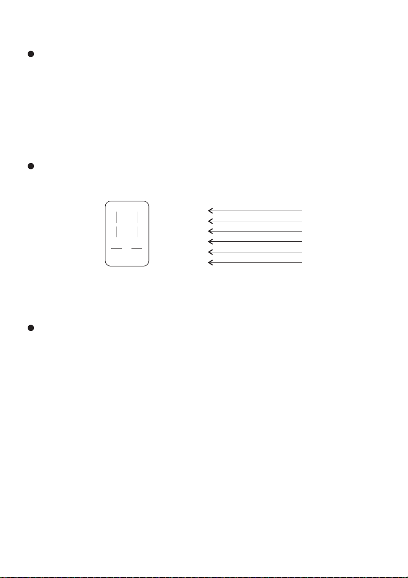
Do not cover the opening of the cabinet with cloth and plastic or to install this unit
in poor ventilated places. Allow 10cm between this unit and its surroundings.
Do not continue to operate the unit under abnormal conditions such as detection
of smoke, strange smell or no display on screen while power is turned on.
Do not touch the power connection with wet hands.
Do not damage the power cord or leave it under pressure.
Do not operate this unit near magnet, speaker system, etc., to avoid unnecessary
magnetic interference.
Do not drop metallic parts through slots.
Connection cables should be grounded properly.
It will cause damage to the equipment.
The presents of flammable gas or object in the operating environment or exposing this
unit to direct sunlight may cause fire and severe injury.
May cause short circuit, fire and serious damage to this unit.
Unplug this unit and have it checked by qualified service personnel.
May cause overheat. The normal operating temperature is 0 C ~ 40 C.
Contact qualified service personnel for help.
May cause short circuit or electric shock.
May cause fire or shock hazard.
These interference will cause color confusion and screen fluctuation.
This could permanently damage the appliance.
Sudden surge such as lightening will damage the system permanently.
CAUTION
RISK OF ELECTRIC SHOCK
CAUTION
TO REDUCE THE RISK OF ELECTRIC SHOCK,
DO NOT OPEN COVER.
NO USER SERVICEABLE PARTS INSIDE.
REFER SERVICING TO QUALIFIED SERVICE PERSONNEL.
The lightning flash with arrowhead symbol, within an
equilateral triangle, is intended to alert the user to the
presence of uninsulated "dangerous voltage" within the
product's enclosure that may be of sufficient magnitude
The exclamation point within an equilateral triangle is
intended to alert the user to the presence of important
operating and maintenance (servicing) instructions in
to constitute a risk of electric shock to persons.
the literature accompanying the unit.

PREFACE
Thank you for choosing PIH-302 Indoor Pan/Tilt. For trouble free
installation and optimum performance please read this manual
thoroughly before attempting installation or operation.
TABLE OF CONTENTS
PAN/TILT UNIT
INSTALLATION
WIRING OF UNIT
INVERTED MOUNTING
ADJUSTING LIMIT STOPS
MAINTENANCE
CONTROLLER
FRONT/REAR PANEL
WIRING OF PAN/TILT
OPERATION
PAN AND TILT
SYSTEM INSTALLATION
SPECIFICATION
PIH-302 INDOOR PAN/TILT
PIH-302 INDOOR PAN/TILT CONTROL
1
1
1
1
2
2
3
3
3
4
4
5
6
6
6

PAN/TILT UNIT
INSTALLATION
The PIH-302 is intended to be mounted on a PIH-5003 wall Mount. Installation of the pan
and tilt drive to the wall mount requires a stainless steel 1/4-20 screw supplied with the
wall mount. Note the ribs on the underside of the PIH-302 base engage slots in the
PIH-5003. This allows positioning of the PIH-302 in any of four directions with respect to
the wall mount. Secure PIH-302 to the wall mount using screw from underside of wall
mount into PIH-302 and tighten.
WIRING OF UNIT
Fabricate the interconnecting cable in accordance with Figure 1. For proper operation.
Figure 1
PIH-302 Cable Assembly Diagram
1
2
3
4
5
6
AUTO
COMMON
TILT DOWN
TILT UP
PAN LEFT
PAN RIGHT
1
3
2
4
5 6
INVERTED MOUNTING
When the unit is mounted in the inverted position, the leftright directions are reversed for
manual operation. This must be corrected when wiring the cable between control unit and
the pan and tilt drive. Simply reverse leads going to terminals 3 and 4.
1

2
ADJUSTING LIMIT STOPS
After cable is installed and unit has been mounted, proceed as follow:
1. Plug control unit into a 117Va.c.(optional 230Va.c./24Va.c.) source. Be sure auto
switch is in the OFF position.
2. To adjust pan limit stops (see Figure 2), loosen screws securing both stops(1) and (3)
to unit. Slide stops around unit to desired locations and secure by tightening screw.
Right Pan Limit Stop
Limit-Switch Actuator
Left Pan Limit Stop
Camera Mounting Plate
FRONT
4-conductor cable for video signal
Connection to control
Video Output
MAINTENANCE
This pan and tilt drive requires no lubrication or maintenance for the life of the unit. If the
unit fails to function, turn it off and check the fuse on the control unit.
Replacement fuse valuse are given in the instructions supplied with the control unit.
Figure 2

3
CONTROLLER
FRONT/REAR PANEL
LEFT
RIGHT
UP
DOWN
OFF
MAN
AUTO
1
234
FUSE
12
54
63
765
Power / Auto / Manual
Indicate Lamp
Up/Down (Switch 1)
Left/Right (Switch2)
3
4
2
1Fuse
a.c. In
6p-Socket
7
6
5
WIRING OF PAN/TILT
Before connecting pan and tilt controls to the system, slide the module into the card cage
or enclosure from front to back, guiding the line cord through first. To secure the module
in place, loosen the screw on the retaining bracket located on the rear panel of the
module, in the upper right corner. Slide the bracket up and tighten the screw.
12
54
63
Figure 2
Figure 4
Interconnection Diagram, PIH-302C Control
1
2
3
4
5
6
AUTO
COMMON
TILT DOWN
TILT UP
PAN LEFT
PAN RIGHT
Fabricate interconnecting cables according to appropriate cable assembly diagram
(Figure 4).

4
OPERATION
Energize the control unit by plugging the line cord into a power source of the appropriate
voltage. The red power indicator light will illuminate.
PAN AND TILT
Pan is horizontal change in camera direction, moving the field of view to the left or right.
Tilt is a vertical change in camera direction, raising or lowering the field of view.
To pan or tilt the camera, move switches up/down and left/right. The switches control
drives pan and tilt functions simultaneously.
To set the unit for automatic pan operation, switch the AUTO mode. The unit now pans
continuously between the preselected limits.
As manual pan functions (obtained by setting "MAN"), and moving the switch 1 and
switch 2, while a direction of panning is instructed, running will be stopped automatically
at the place of a limited stop.

SYSTEM INSTALLATION
Figure 5
Interconnection Diagram, PIH-302 Control
RIGHT
DOWN
LEFT
UP
AUTO
5
6
3
4
1
2
MAN
AC
Figure 6
Interconnection Diagram, PIH-302
S3
S2
S1
S4
9
9
5
1
R
R
812
R
M
M
M
M
R
R
U
D
L
1314
2
6
5
1
4
3
S1
S4
S3
S2
UPPER VIEW
(Inside of the unit)
5

SPECIFICATION
PIH-302 INDOOR PAN/TILT
6 66-302CSE-3
Angular Travel
Limited Stop
Speed
Load Rating
Duty Cycle
Input Voltage
Motor Output
Normal Operating Current
Cable Requirement
Operating Temperature
Construction
Finish
Dimensions
Weight
Pan 350 Tilt 60
Externally adjustable
Pan 5.5 / second Tilt 3 / second
Pan 7kgs Tilt 4kgs
Pan continuous Tilt Intermittent
a.c. 24V/117V/230V, 50Hz/60Hz
6 watts
24V-0.083A, 117V-0.16A, 230V-0.2A
Six conductor, unshield
-25 ~ +60
Aluminum and plastic
Off white baked enamel finish
184 (H) x 115 ( )mm
1.9 kgs
PIH-302C INDOOR PAN/TILT CONTROL
Control Buttons
Input Voltage
Output Voltage
Environment Temperature
Operating
Construction
Dimensions
Weight
Auto / Off / Manual, Left / Right, Up / Down
a.c. 117V/230V, 50Hz/60Hz
a.c. 24V/117V/230V, 50Hz/60Hz
Steel, with silver gray baked enamel finish
152(W) x 58(H) x 188(D)mm
1.25 kgs
-10 ~ +60

INDOOR PAN/TILT WITH CONTROL
PIH-302/302C
INSTRUCTION MANUAL
66-302CSE
MERIT LILIN ENT. CO., LTD
http://www.meritlilin.com
This manual suits for next models
1
Table of contents
Other Lilin Camera Accessories manuals