Lime D15.0 User manual

- -
0
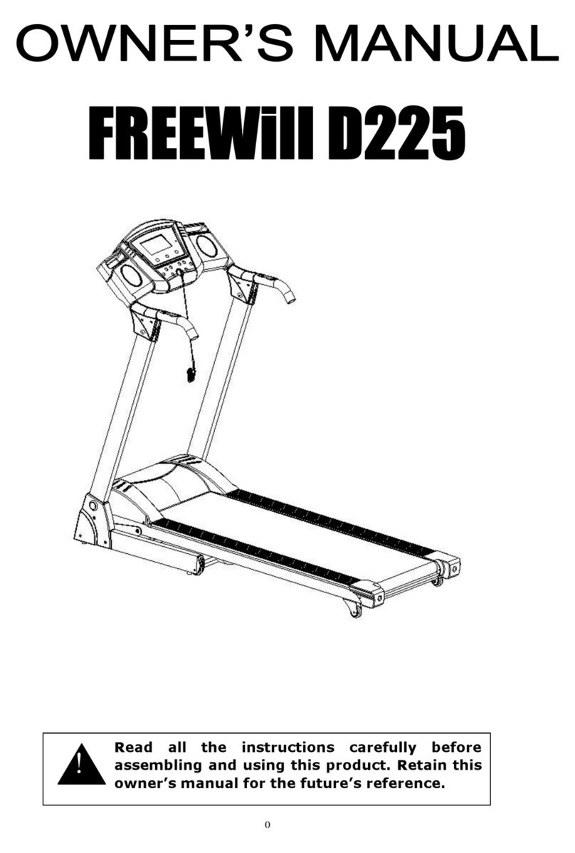
OWNER'S MANUAL

- -
1
CATALOG
CATALOG____________________________________________ 1
WARNING____________________________________________ 2
ATTENTION___________________________________________ 2
IMPORTANT SAFETY PRECAUTIONS______________________ 3
ASSEMBLY INSTRUCTION_______________________________ 5
TECHNICAL PARAMETER_______________________________ 9
OPERATION GUIDE____________________________________ 10
TROUBLESHOOTING GUIDE_____________________________ 22
MAINTENANCE INSTRUCTIONS__________________________ 24
EXPLODED DRAWING__________________________________ 2
PARTS LIST___________________________________________ 27

- -
2
WARNING
Read all instruction carefully before use this product. Retain this owner’s manual for the future’s
reference:
----When using this treadmill, keep attaching the safety pull pin rope to your clothes.
----When you are running, keep your hand swinging natural, stare front,
never look at the bottom of your foot.
----Add the speed step by step when runnin, and await that you adapt the speed, then add it.
----When the emergency happens, pls put down the emergent stop press-button immediately.
---- eave the treadmill after the running belt stop stably.
Caution: Read the assembly instruction carefully ,assembly this treadmill follow it.
ATTENTION
1.- Before starting any exercise program, consult with your physician or health professional.
2.- Check all the bolts locked.
3.- Never put the treadmill in the wetness ai,otherwise,will cause troubles.
4.- We will take no responsibility for any troubles and hurts due to the reasons above.
5.- Dress sport clothes and shoes before you run.
6.- Do not do exercise in 40 minutes after dinner.
7.- To prevent hurts, pls warm up before exercise.
8.- Consult with doctor before exercise if have high blood pressure.
9.- This treadmill is only used for adults。
10、- Give the olds, childs and handicapped the good care, guide and supervision.
11、- Don’t plug anything into any parts of this equipment, if not, will damage it.
12、- Don’t connect line in the middle of cables, lengthen cable, or
change the cables plug;do not put any heavy things on cables or
put it near the heat source;forbid using the socket with several
holes, otherwise,will cause fire or be hurt by power.

- -
3
13、 When don’t use the equipment, cut off the power.When cut off the power,don’t pull the power
supply line so as to keep the wire un broken.
IMPORTANT SAFETY PRECAUTIONS
1. Plug the power cord of the treadmill directly into a dedicated grounded circuit carrying 10 amps.
Grounding Instructions:
This product must be grounded. If it should breakdown, grounding provides a path of least resistance for
electric current to reduce the risk of electric shock.
2. Position the treadmill on a clear, level surface. Do not place the treadmill on thick carpet as it may
interfere with proper ventilation. Also, do not place the treadmill near water or outdoors.
3. Position treadmill so that the wall plug is visible and accessible.
4. Never start the treadmill while you are standing on the walking belt. After turning the power on and
adjusting the speed control, there may be a pause before the walking belt begins to move. Always stand on
the foot rails on the sides of the frame until the belt is moving.
5. Wear appropriate clothing when exercising on the treadmill. Do not wear long, loose fitting clothing that
could become caught in the treadmill. Always wear running or aerobic shoes with rubber soles.
6. Always unplug the power cord before removing the treadmill motor cover.
7. Keep small children away from the treadmill during operation.
8. Always hold the handrails when initially walking or running on the treadmill, until you are comfortable with
the use of the treadmill.
9. Always attach the safety pull pin rope to your clothing when using the treadmill. If the treadmill should
suddenly increase in speed due to an electronics failure or the speed being inadvertently increased, the
treadmill will come to a sudden stop when the pull pin is disengaged from the console.
10. When the treadmill is not being used, the power cord should be unplugged and the safety pull pin
removed.
11. Before starting any exercise program, consult with your physician or health professional. He or she can
help establish the exercise frequency, intensity (target heart zone) and time appropriate for your particular
age and condition. If you have any pain or tightness in your chest, an irregular heartbeat, shortness of breath,
feel faint or have any discomfort while you exercise, STOP! Consult your physician before continuing.
12. The maximum user weight is limited 200 Kgs.
13. Please leave 2.00 mts X 1.00 mts, or 3 to 4 feet, as a safety area behind the equipment.

- -
4
14.The power cable of treadmill is special. if the power cable is damaged, please don't change by yourself,
you must contact the local dealer ASAP.
15.When the treadmill is not being used, please pull out the safety lock and store it in a safe location. In
order to avoid the unauthorized use by others, specifically children.
For your information, please note following electronical specification of Treadmill:
a. The rated power input is 1,500 W.
b. Power voltage supply is 110 V – 127 V.
c. Rated frequency is 50 – 60 Hz.

- -
5
ASSEMBLY INSTRUCTIONS
When you open the carton, you will find the below spare parts:
SPARE PARTS LIST:
NO.
DES. SPEC. QTY(pcs)
NO.
DES. SPEC. QTY(pcs)
1 MAIN FRAME
1 91 BO T M5*10 2
3
EFT UPRIGHT
TUBE 1 102
SCREW ST4.2*12 4
4
RIGHT
UPRIGHT
TUBE
1 126
DUMBBE BRACKET 1
5 COMPUTER 1 127
2 B DUMBBE 2

- -
6
13
EFT
HAND EBAR
BOTTOM
COVER
1 128
3 B DUMBBE 2
14
RIGHT
HAND EBAR
BOTTOM
COVER
1 129
4 B DUMBBE 2
38
EFT P ASTIC
BOTTOM
COVER
1 182
SCREW ST4.2*19 4
39
RIGHT
P ASTIC
BOTTOM
COVER
1 183
BO T M8*15 2
47 PEDA COVER
1 5#A EN WRENCH 1
57 WASHER 10 14 A EN WRENCH 1
61 WASHER 8 2 WRENCH W/SCREW DRIVER
1
63 BO T M10*25
14
FIXING TOOLS:
#5 ALLEN WRENCH (5mm): 1pcs
# ALLEN WRENCH ( mm): 1pcs
WRENCH W / SCREW DRIVER (S = 13, 14, 15): 1pcs
ASSEMBLY INSTRUCTION:
STEP 1:
STEP 2:
1. Open the carton, take out the spare parts,
and put the MAIN FRAME (#1) on the
ground.
2. Connect the signal line (#145) at the end of
the EFT UPRIGHT TUBE (#3) and the signal
line (#146) at the bottom of the MAIN FRAME
(#1), then insert the EFT UPRIGHT TUBE (#3)
into the unit.
Notice: Don’t do assembly with strong
force, you may break the insulating layer of
the signal line, or the plug pins may be
curved, which would result in bad signal
connections.
3. Put the BO T (#63) and the WASHER (#57)
together,then lock the EFT UPRIGHT TUBE
(#3) onto the MAIN FRAME
(#1) with #6 A EN

- -
7
4. Insert the P ASTIC BOTTOM COVER
(#38, #39) into the UPRIGHT TUBE (#3, #4)
vertically.
Notice: Please don’t tighten the bolts and
nuts until all the assembly steps are
completed.
5. Insert the HAND EBAR BOTTOM COVER (#13, #14)
into the UPRIGHT TUBE (3, 4) separately.
6. Connect the signal lines (#110, #113, #144) on both
side of the COMPUTER (#5) and the signal lines (#111a,
#114a, #145a) of the UPRIGHT TUBES (#3, #4); then
insert the COMPUTER (#5) into the left and right upright
tube.
7. Put the BO T (#63) and the WASHER (#57) together,
then lock the COMPUTER (#5) onto the UPRIGHT
TUBES (#3, #4) with #6 A EN WRENCH.
Notice: Please don’t tighten the bolts and nuts until
STEP 3:
STEP 4:
STEP 5:

- -
8
8. Use WRENCH W / SCREW DRIVER to lock
the HAND EBAR P ASTIC BOTTOM
COVER (#13, #14) onto the COMPUTER (#5)
with SCREW (#102) .
9. ock the P ASTIC BOTTOM COVER (#38,
#39) onto the MAIN FRAME (#1) with the
SCREW (#147).
13. Put the DUMBBE (#127, #128, #129) on
the DUMBBE BRACKET (#126).
9. Put the BO T (#183) and the WASHER
(#61) together, then lock the DUMBBE
BRACKET (#126) onto the EFT AND RIGHT
UPRIGHT TUBE (#3, #4) with #5 A EN
WRENCH.
STEP :
STEP 7:
STEP 8:

- -
9
STEP 9:
Notice: Please don’t tighten the bolts and nuts until all the assembly steps are completed.
The following operation is based on the good assembled of the above operation.
TECHNICAL PARAMETER
BUI T UP SIZE
(mm)
2,030 X 920 X
1525
SPEED RANGE 1.0-20 Km/h
0.8-12 mph
FO DAB E
SIZE (mm) 1150 X 920 X NET WEIGHT 156 Kg
14. After complete the assembly
above, upright the treadmill (as the left
drawing), hook plastic bearing (51) of
the adjustable holding with the pedal
draw (49).
15. Put the pedal connecting piece (99)
under the pedal (47) on the back of the
pedal hook (49); use the WRENCH
W / SCREW DRIVE, to lock the BO T (91)
and the pedal connecting piece (99).
Notice: pedal draw must hook well.

- -
10
1720
RUNNING
BOARD SIZE
(mm)
1520 X 520 INC INE 0-12%
MAX A OWED
WEIGHT 200 Kg
5 ED DISP AY SPEED, TIME, DISTANCE, CA ORIE, PU SE, INC INE,
WITH 7 INCH VIDEO DISP AY
OPERATION GUIDE

- -
11
1. Keys define:
1-1. Speed up: control the speed and input the data.
1-2. Speed down: control the speed and input the data.
1-3. Incline up: control the motorized incline up and input the data.
1-4. Incline down: control the motorized incline down and input the data.
1-5. Function mode / clear / program.
1-6. Start: Start the motor and operation system.
1-7. Stop : Stop the motor / Clear.
1-8. Speed Quick Access Keys: 10 / 12 keys: Programmable.
1-9. Incline Quick Access Keys: 7 keys: Programmable.
1-10. FAN Key : Open / Close the fan.
1-11. KM/M KEY: KM/M transformation function
2. System Memory Mapping and Option Setting Mode:
2-1. Options: Directly enter the MANUA state after show 1 second, eg:
2-1-1. The main window display: Display with the circle of dummy playground (400 M) when it is running ;
Display with rolling “ IME” logo when it is in the standby mode.
2-1-2. Speed window display: min speed eg. “1.0 KM or 0.8 M”.
2-1-3. Incline window display: min incline eg. “0”.
2-1-4. Dist window display: min DIST eg. “0.00”.
2-1-5. The distance of each circle of the playground: 400 m: 1 point-20m.
3. Program profile and setting.
3-1. Manual profile: speed / incline: Default: min.
3-2. User Profile: Default: min. When the default is set, it will be stored; when the incline is regulated, it
will get back to default=min.

- -
12
3-3. In the profile window, the speed and incline of each program will display automaticly, the
interval
time is 5s. The profile window is 8 X 8 dot matrix. It can only display 8 profile when the process is
carrying out. Therefore, when the quantity of the setting profile is beyond 8, it will adopt the
progressive display, namely the first line of the profile will flicker, then turn to the second line. The
first line will move automaticly and the second line will become the first line……the ninth line
become the eighth line, the window is full with lines until the final profile become the eighth line.
The profile will get back to its original state after the alarm of the end of the profile operation.
3-4. The window will be floating display from the first line under the stop state. The revolving lamp will
display and the window will show speed profile under the stop state. (The floating means are the
same as 3-3.)
3-5. Each Incline / Speed profile
P1
Incline profile 1
Segment
1 2 3 4 5 6 7 8 9 10 11 12 13 14 15 16 17 18 19
20
EEPROM
1 1 2 2 2 3 3 2 2 1 2 2 2 1 1 3 3 2 2 2
Speed profile 1
Segment
1 2 3 4 5 6 7 8 9 10 11 12 13 14 15 16 17 18 19
20
EEPROM
2.0
3.0
3.0
4.0
5.0
3.0
4.0
5.0
5.0
3.0
4.0
5.0
4.0
4.0
4.0
2.0
3.0
3.0
5.0
3.0
P2
Incline profile 2
Segment
1 2 3 4 5 6 7 8 9 10 11 12 13 14 15 16 17 18 19
20
EEPROM
1 2 2 2 2 3 3 2 2 2 2 2 3 3 3 4 4 3 2 2
Speed profile 2
Segment
1 2 3 4 5 6 7 8 9 10 11 12 13 14 15 16 17 18 19
20
EEPROM
2.0
4.0
4.0
5.0
6.0
4.0
6.0
6.0
6.0
4.0 5.0
6.0
4.0
4.0
4.0
2.0
2.0
5.0
4.0
2.0
P3
Incline profile 3
Segment
1 2 3 4 5 6 7 8 9 10 11 12 13 14 15 16 17 18 19
20
EEPROM
1 1 3 2 2 2 3 2 2 1 2 2 2 1 1 2 3 2 2 1
Speed profile 3
Segment
1 2 3 4 5 6 7 8 9 10 11 12 13 14 15 16 17 18 19
20
EEPROM
2.0
2.0
3.0
5.0
5.0
4.0
5.0
6.0
4.0
4.0
4.0
5.0
4.0
4.0
3.0
2.0
2.0
2.0
3.0
2.0
P4
Incline profile 4
Segment
1 2 3 4 5 6 7 8 9 10 11 12 13 14 15 16 17 18 19
20
EEPROM
2 3 3 2 2 3 3 3 2 2 2 2 4 4 4 6 6 3 2 2
Speed profile 4
Segment
1 2 3 4 5 6 7 8 9 10 11 12 13 14 15 16 17 18 19
20
EEPROM
3.0
5.0
5.0
6.0
7.0
7.0
5.0
7.0
7.0
8.0
8.0
5.0
9.0
5.0
5.0
6.0
6.0
4.0
4.0
3.0
P5
Incline profile 5
Segment
1 2 3 4 5 6 7 8 9 10 11 12 13 14 15 16 17 18 19
20
EEPROM
1 2 3 2 2 4 3 2 1 2 2 2 4 3 4 5 4 3 2 1
Speed profile 5
Segment
1 2 3 4 5 6 7 8 9 10
11 12
13
14 15
16
17
18
19
20

- -
13
EEPROM
3.0.
5.0
5.0
6.0
7.0
7.0
5.0
7.0
7.0
8.0
8.0
6.0
7.0
5.0
5.0
6.0
7.0
4.0
4.0
3.0
P
Incline profile 6
Segment
1 2 3 4 5 6 7 8 9 10 11 12 13 14 15 16 17 18 19
20
EEPROM
2 3 3 2 4 6 2 2 5 3 2 4 2 2 2 2 5 2 2 1
Speed profile 6
Segment
1 2 3 4 5 6 7 8 9 10 11 12 13 14 15 16 17 18 19
20
EEPROM
2 5 7 8 9 6 4 7 4 5 8 9 7 6 8 5 8 6 4 3
P7
Incline profile 7
Segment
1 2 3 4 5 6 7 8 9 10 11 12 13 14 15 16 17 18 19
20
EEPROM
4 5 5 5 6 6 6 7 8 9 9 9 10 10 10 12 12 8 6 3
Speed profile 7
Segment
1 2 3 4 5 6 7 8 9 10 11 12 13 14 15 16 17 18 19
20
EEPROM
2.0
3.0
3.0
6.0
7.0
7.0
4.0
6.0
7.0
4.0
6.0
7.0
4.0
4.0
4.0
2.0
3.0
4.0
4.0
2.0
P8
Incline profile 8
Segment
1 2 3 4 5 6 7 8 9 10 11 12 13 14 15 16 17 18 19
20
EEPROM
3 5 5 5 4 4 4 3 3 3 3 4 4 4 3 3 3 4 3 2
Speed profile 8
Segment
1 2 3 4 5 6 7 8 9 10 11 12 13 14 15 16 17 18 19
20
EEPROM
2.0
4.0
4.0
4.0
5.0
6.0
8.0
8.0
6.0
7.0
8.0
8.0
6.0
4.0
4.0
2.0
5.0
4.0
3.0
2.0
P9
Incline profile 9
Segment
1 2 3 4 5 6 7 8 9 10 11 12 13 14 15 16 17 18 19
20
EEPROM
3 3 5 5 4 3 4 4 2 2 3 3 4 4 3 2 3 4 3 2
Speed profile 9
Segment
1 2 3 4 5 6 7 8 9 10 11 12 13 14 15 16 17 18 19
20
EEPROM
2.0
2.0
4.0
4.0
6.0
5.0
5.0
8.0
6.0
6.0
8.0
5.0
6.0
4.0
3.0
3.0
5.0
4.0
3.0
2.0
P10
Incline profile 10
Segment
1 2 3 4 5 6 7 8 9 10 11 12 13 14 15 16 17 18 19
20
EEPROM
4 4 4 4 3 3 6 6 6 7 7 8 8 9 9 6 6 5 3 3
Speed profile 10
Segment
1 2 3 4 5 6 7 8 9 10 11 12 13 14 15 16 17 18 19
20
EEPROM
2.0
3.0
3.0
3.0
4.0
5.0
3.0
4.0
5.0
3.0
4.0
5.0
3.0
3.0
3.0
6.0
6.0
5.0
3.0
3.0
P11
Incline profile 11
Segment
1 2 3 4 5 6 7 8 9 10 11 12 13 14 15 16 17 18 19
20
EEPROM
4 5 5 5 6 6 6 7 8 9 9 9 10 10 10 12 12 8 6 3
Speed profile 11
Segment
1 2 3 4 5 6 7 8 9 10 11 12 13 14 15 16 17 18 19
20
EEPROM
2.0
3.0
3.0
6.0
7.0
7.0
4.0
6.0
7.0
4.0
6.0
7.0
4.0
4.0
4.0
2.0
3.0
4.0
4.0
2.0
P12
Incline profile 12
Segment
1 2 3 4 5 6 7 8 9 10 11 12 13 14 15 16 17 18 19
20
EEPROM
3 3 5 5 7 6 7 8 8 12 12 9 11 10 10 11 11 8 6 3
Speed profile 12
Segment
1 2 3 4 5 6 7 8 9 10 11 12 13 14 15 16 17 18 19
20

- -
14
EEPROM
2.0
4.0
4.0
5.0
7.0
5.0
4.0
7.0
7.0
4.0
6.0
6.0
4.0
5.0
4.0
2.0
5.0
4.0
3.0
4.0
P13
Incline profile 13
Segment
1 2 3 4 5 6 7 8 9 10 11 12 13 14 15 16 17 18 19
20
EEPROM
5 5 5 6 6 6 4 4 6 6 5 5 8 8 9 9 9 7 4 2
Speed profile 13
Segment
1 2 3 4 5 6 7 8 9 10 11 12 13 14 15 16 17 18 19
20
EEPROM
2.0
4.0
4.0
7.0
7.0
4.0
7.0
8.0
4.0
8.0
9.0
9.0
4.0
4.0
4.0
5.0
6.0
3.0
3.0
2.0
P14
Incline profile 14
Segment
1 2 3 4 5 6 7 8 9 10 11 12 13 14 15 16 17 18 19
20
EEPROM
5 6 6 6 7 5 8 8 4 4 4 5 5 8 8 10 10 8 6 3
Speed profile 14
Segment
1 2 3 4 5 6 7 8 9 10 11 12 13 14 15 16 17 18 19
20
EEPROM
2.0
4.0
5.0
6.0
7.0
5.0
4.0
6.0
8.0
8.0
6.0
6.0
5.0
4.0
4.0
2.0
4.0
4.0
3.0
3.0
P15
Incline profile 15
Segment
1 2 3 4 5 6 7 8 9 10 11 12 13 14 15 16 17 18 19
20
EEPROM
3 4 5 4 6 5 6 4 3 3 3 5 5 6 7 6 8 5 4 3
Speed profile 15
Segment
1 2 3 4 5 6 7 8 9 10 11 12 13 14 15 16 17 18 19
20
EEPROM
2.0
3.0
3.0
6.0
7.0
5.0
4.0
5.0
7.0
8.0
6.0
7.0
5.0
5.0
6.0
3.0
4.0
4.0
3.0
2.0
PS: Pls. Attention that the in above profile, the red documents of EEPROM are all display data, instead of
number Moreover, the Speed is displayed in Mile data.
4-1. Safety key: normal close / active open:
4-1-1. When we open the safety key, the hardware power off, the motor & incline motor will be stop at
once.
4-1-2. When it starts, it will return to the incline motor, the display default will choose the states of the
program.
4-2. Start / stop key:
4-2.1. When we press the “start key”, it will make a signal output as per the choosing program. The signal
is more adjustive.
4-2.2. When we press the “stop key”, the treadmill will stop immediately, the DC motor will decline slowly
to stop state and all of the data will clear.
4-3. Program Key: Press the key under the stop state, choosing the program which we want, 2
seconds later, the ED will display the relative profile graph. The operation processes are as
follows:
M→ P1→P2→ P3→ P4→P5→P6→P7→…P15→U1→U2→U5→M.
When we choose P1~P12 or USER program, the dot matrix will firstly show the number of this
program, then show the profile of this program. For example, when we choose P15, the dot
matrix will firstly show 15, 2s later, the profile of the program will come out. If we continuously
press the Program Key to cycle the program, the dot matrix will only show the program number.
The profile will be never showed unless we release the press in 2s.
4-4. Clear key:
4-4.1. All the parameter will be clear when we press this key, whenever it is in the stand by state, setting
processes or we press the STOP key. The incline will get back to its original data and the system
will return to its stand by state. However, it will not be available when it is in the running state.

- -
15
4-5. MODE key:
4-5.1. When it is in the MANUA stand by state, press the mode key, choosing ordinally the item you
want, the sequence of the items will be as follows:
Time → Calories → Distance
When we choose the other programs, except the MANUA , press the MODE in its stand by state,
we can only set TIME, but CA , DIST are not available.
4-5.2. Press the up, down key of the speed / Incline to change the data.
4-5.3. When we set the distance, the indicator light will be up, the data flicker, the default values of is
0.0, step 1. The set ranges are as follows:
0.0 → 1.0 → 2.0 → 3.0 →………→ 98.0 → 99.0 → 0.0
4-5.4. When we set the calories, the indicator light will be up, the data flicker, the default value is 0,
step 5. The set ranges are as follows:
0 → 5 → 10 → 15 → ……… → 990 → 995 → 0
4-5.5. If you can’t confirm in 20s when you are setting the program, it will automaticly set the final data.
4-6. Speed up key:
4-6-1. The parameter of the TIME or DIST or CA can be adjustable in the setting state.
4-6-2. It can speed up in the start state.
4-7. Speed down:
4-7-1. The parameter of the TIME or DIST or CA can be adjustable in the setting state.
4-7-2. It can speed down in the start state.
4-8. Incline up key:
4-8-1. The operation process is the same as the “speed up key” in the setting state.
4-8-2. It can incline up in the start state.
4-9. Incline down key.
4-9-1. The operation process is the same as the “speed down key” in the setting state.
4-9-2. It can be incline down in the start state.
4-10.
Quick access keys:
ITEM The setting of Speed key address, the setting ranges Min~Max, default
are as follows:
Mile Default
1 2 3 4 5 6 7 8 9 10 11 12
Key K 1 K 2 K 3 K 4 K 5 K 6 K 7 K 8 K 9 K 10
K 11
K 12
4-11. FAN Key: Open or close the fan.
4-12. KM/M KEY: We can press the key to have a KM/M transformation when it is under the stand by
state; the ED indicator light will change at the same time.
4-13. Compound KEY: KM/M KEY: We can press the key to have a KM/M transformation when it is under
the stand by state. The ED indicator light will change at the same time. The “K” or “M” letters will
display synchronously in the dot matrix.
5. The brief description of function
5-1. Open the treadmill, safety key on, When the ED display 1s, it will directly enter the MANUA state
ITEM
The setting of Speed key address, the
setting ranges Min -
Max, default are
as follows:
Default 0 2 4 6 8 10 12
Key K 1 K 2 K 3 K 4 K 5 K 6 K 7

- -
16
and the incline should be got back to the original data.
5-2. Whatever the manual, p1~p15, user are all in their stand by state, when we press the start key, it
will begin to count down in 3 seconds with the alarm “bi-bi-bi” and the letter of “GO” which are
showed in the middle of dot matrix. The computer will be open too, the details are:
3(bi)-2(bi)-GO-START.
5-3. Scan function:
5-3-1. In the START MODE, it will display cycledly “incline/speed profile, multi-data (incline/pulse, cal/dist)
for each 5s. The relative indicator light will be lighted when we choose the specific function; when
we press the incline key, the indicator light of the compound function will transform into the function
which the key will show.
5-4. Program function:
5-4-1. It will show a playground when it is in MANUA state.
5-4-2. It will show profile in the dot matrix ED.
---Program, user display Incline / Speed profile. Incline/Speed profile are both sharing window.
---User program take the use of speed / incline up, down key to adjust the incline / speed profile.
---The exercise time which the program preset is 20 min. When the operating time is set, the
operating time per section is average. If it is not set, 1 min per section.
Speed: End” and flicker 40 times, tweeting twice. 50s later, all the window will be clear into the
stand by state. During the 50s, if any keys be pressed, it will get back to the stand by state.1 min is
preset per section under the program of P1~P15, U1~U5. (1*20=20 min)
5-6-3. When time is calculated by Count down, the setting range is 05:00~99:00. When count down to
zero, alarming twelve times and data of the window will be flickering, everything will stop and the
motor will stop too.
5-7. Distance
5-7-1. Distance is calculated by Count up & Count down. Distance will be calculated by count down if it is
preset. It will be calculated by count up it isn’t preset.
5-7-2. When distance is calculated by Count up, the counting range is 0.00~99.9. It will be clear and
calculate once more if it is beyond the range.
5-7-3. When distance is calculated by Count down, the counting range is 1.00~99.0. When count down to
zero, alarming twelve times and data of the window will be flickering, everything will stop, power is
disable and motor stop.
5-7-4. Setting distance: press mode key, data flash.
5-8. Calories
5-8-1. Calories is calculated by Count up & Count down. Calories will be calculated by count down if it is
preset. It will be calculated by count up it isn’t preset.
5-8-2. When calories is calculated by Count up, the counting range is 0~999, it will be clear and calculate
once more if it is beyond the range. When calories is calculated by Count down, the setting range is
5.0~995, step ±5. When count down to zero, alarming twelve times and jump to setting state, motor
stop.
5-8-3. CA =0.0049*speed*time*: 1+?%.

- -
17
Time unit: seconds; ?% is motor incline.
5-9. Incline:
5-9-1. It will display in Multi-data (incline, pulse) window. The motor incline will be up and down if you
press the incline up and down key.
5-9-2. Incline regulation: adopts manual into self-regulation program. Press INC INE UP/DOWN +STOP
5s simultaneously in the stand by state, it will directly enter the INC INE self-regulation.
Regulation process:
5-9-3. Display “Inc” (Speed window), “Hi”(Time window), the Max. data of incline VR (INC/PU SE window)
and the actual value of incline VR (CA window) in the seven segment display window.
5-9-4. Display “Inc” (Speed window), “ o”(Time window), the Min. data of incline VR (INC/PU SE window)
and the actual value of incline VR (CA window) in the seven segment display window.
5-9-5. When e3 or e4 display in the regulation process, Pls. Open the safety key or restart the power to
leave the regulation process.
5-10. PU SE:
5-10-1. The window will be clear and display “P” if no any signal output for 8s.
5-10-2. If the input signal >240 and <40, the window will be clear and display “P” if it is continuing for 10s.
6. Profile setting and program control
6-1. Setting Bar + oop mode; When we adjust work line with up, down key, it will enter display bar
mode, 5s later, it will get back to display loop mode.
6-2. The window will show loop “ “ when one loop is finished. The counting range is 1~ 99. Showing
3s later, It will display loop. If the loop display and work line adjustation are working simultaneously,
the main display is still loop, but the work line is adjusted at the same time. When the loop display
is over, it will display by bar, loop, loop/bar, etc. 3 modes.
6-3. Manual revolving lamp
Anticlockwise and circular display. The lamp will be lighted ordinally from the first light when it is start, when
the first loop is over, the lamps will turn off, then begin once more with cycle.
6-4. Manual playground: the distance of per loop is 400m. (1 point=20m)
6-5. Manual: The user can set all of the work line, the program will display M, the dot matrix will show
the revolving lamp.
6-6. The time default will show 0:00 if the user don’t press the mode key of the Manual or program.
When we press the start key, the program will begin to calculate the data and the signal will output
as per the program profile.
6-7. Profile takes the principle of the middle location and display mode by 8*8 dot matrix.
6-8. The working state when we choose the Program:
6-8-1. 3s before the newline of the profile, the data of the incline/speed window will be always flickering
until the next newline begins.

- -
18
6-8-2. When we choose the program and press the start key, the orientation and control of INC/Speed will
carry out automatically as per the profile curve of program display on the ED Bar. Meanwhile,
INC/Speed will adjust and orientate automatically.
6-8-3. Each program has 20 segments, the practice time of every segment is 1min(when time is showed
with count up). 20 segments finished is 1 loop. Every data will be clear when we press the stop key
during practice of the program.
6-8-4. The practice time of each segment is the time set up /20min if the time is set as count down mode;
when time count down to zero and restart, the practice time of each segment is 1 min.
6-8-5. When the program is carrying out, we can press the speed up/down key to adjust the speed data
for each segment, the ED bar and speed will adjust simultaneously.
7. User program:
The Program display U “n” (n from number 1 - 5)
When process U1~U5 Program, Speed/incline Profile will display per 5s interval
7-1. Press“mode key” to enter into the setting of models then the Profile display glittering.
Time→ Speed Profile 1~20 BAR → incline Profile 1~20 BAR → TIME
7-2. When user program have set, press “KM/M “key to exchange, all the programs the user set
before are clear off. The user must reset programs.
7-3. When not press mode key, the time default display 0:00; press start key, the program will calculate
all kinds of data, and output the message according to the profile graph.
7-4. Press mode key, the flash will present according to the segment, press up / down key to
set the
profile, the graph won’t stop until all 20 programs finished setting, or press start key for releasing
from the setting mode, the profile set up will save to EEPROM in case take out the database
7-5. When we choose the program and press the start key, the orientation and control of incline/Speed
will carry out automatically as per the profile curve of program display on the ED Bar. Meanwhile,
incline/Speed will adjust and orientate automatically.
7-6. A loop including 20 segments, press the “stop” key to stop it during it is running.
7-7. The next speed and incline will be flashed before 3s when it is newlining.
7-8. The practice time of each segment is the time set up /20min if the time is set as count down mode;
when time count down to zero, time count down is not set and restart, the practice time of each
segment is 1min.
a). Manual profile display:
b). 8*8 profile area:

- -
19
Error message: display on speed window.
8-1. E1. The program will stop automatically when press “start” key but no speed program input in 10s.
8-2. E2. Either the EEPROM nor the ID code is wrong, or can not reading; this action won’t accept
unless it last for 5s.
8-3. E3. Incline VR value is not changed when revise it in 6s in a row.
8-4. E4- Incline VR of A / D value is reverse when reversing.
8-5. To press the any key to exit when E1 appear
8-6. To press the enter key 2sec to exit when E3 / E4 appear, then come back to stand by state.
9. Operation instructions for Multimedia player
Keys instruction:
There are 10 keys from this system, including “INPUT”, “ /ENTER”, “GO BACK”, “VO -“,
“VO +”, “▼”, “▲”, “ “, “ ”, ”MEDIA / POWER” .
9-1. The display will be in loading status when the treadmill is running. About 2 seconds later, the TFT
window will display two icons: Memory and Setup. You can insert the SD/MMC card into the card
seat or insert the Flash disk to the USB port. Thus, the screen will display four icons: SD, USD,
Memory and Setup. Pls refer to Picture 1.
Picture 1 Picture 2 Picture 3
9-2. You can choose SD, USD, Memory and Setup by “ , ”, confirm your choice by “ /ENTER”,
then it will go to the son menu. As shown by Picture 2.
9-3. If you choose “Setup”, you can select the items circularly by “▲”, “▼”, these items includes
“language-> Picture displayed speed-> Picture displayed usage->Music repeating mode->Movie repeating
mode-> Picture displayed proportion->Automatic player->Default setting”(See picture 3). You can choose or
switch the items by “ , ”, then press “ /ENTER”to confirm.
I. If you select “language”, you can choose the “ Sample Chinese->Espanol->English” circularly by “ ,
” then press “ /ENTER ”to confirm.
II. If you select “Picture displayed speed”, you can choose”3sec->5sec->15senc->1 min->15min->1
hour” circularly by “ , ”, then press “ /ENTER” to confirm.
Table of contents