FG4000 – installations and specifications
FG4000 mtpa – rev. 01/2020
1. Content
1. Content ................................................................................................ 3
2. Electromagnetic flowmeter installation ............................................. 4
3. Contents of the measuring device supply ......................................... 4
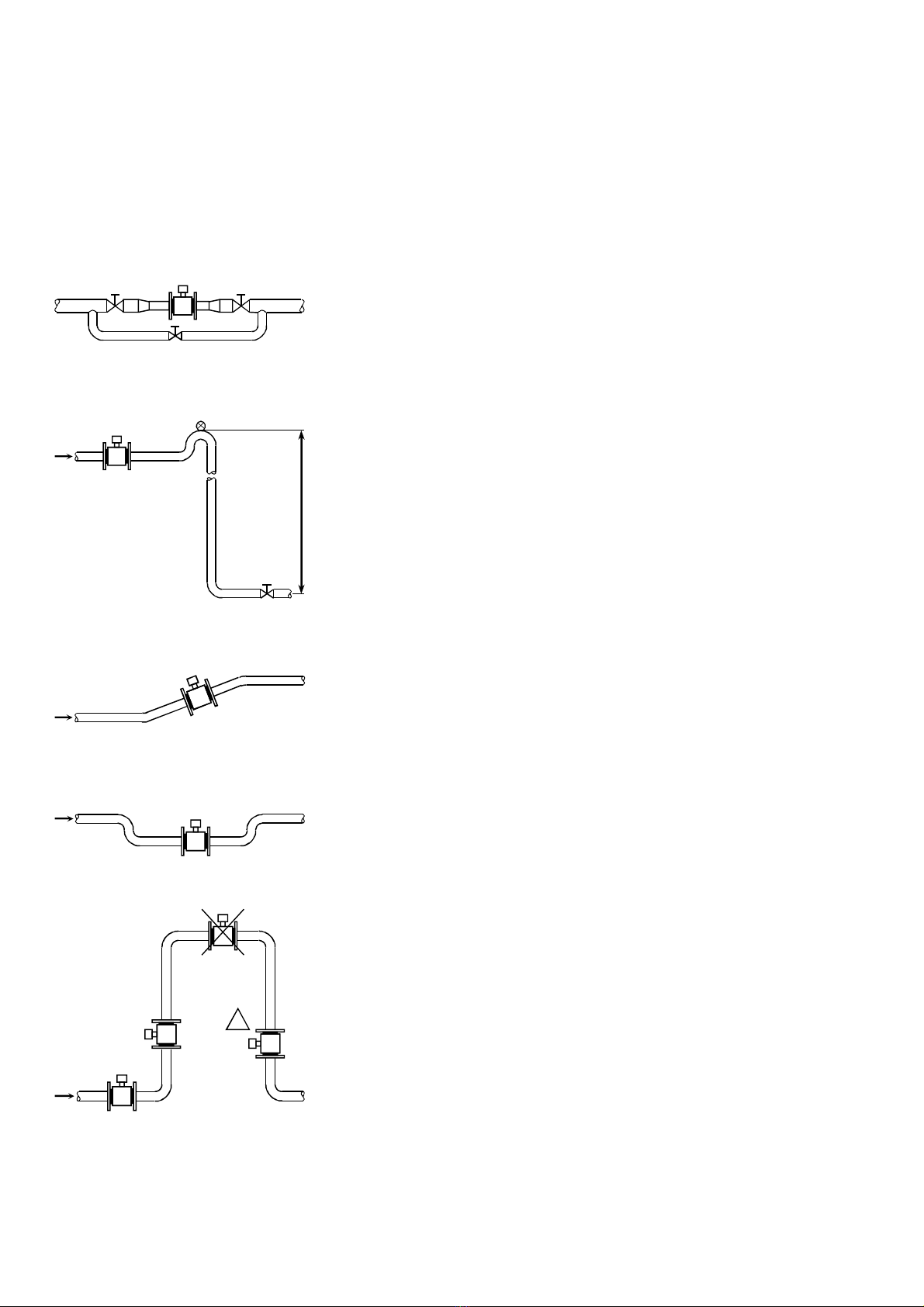
4. Selecting size of and installing electromagnetic flowmeter ............. 4
4.1. Optimum liquid velocity in the flowmeter measuring tube ................................... 5
4.2. Conditions for steady flow inside of the flow sensor ........................................... 5
4.3. nsurance of the filling the entire cross section area of the flowtube .................. 5
4.4. The flowtube sensor direction ........................................................................... 5
4.5. nsurance of flooding sensor electrodes .......................................................... 5
4.6. Prevention before influence of bubbles in measured liquid................................. 5
4.7. Prevention before influence of sludge inside the measuring tube (electrodes) .... 6
4.8. The ambient conditions (temperature, humidity, vibrations) ............................... 6
4.9. Temperature and pressure of measured liquid. ................................................. 6
4.10. Installation of sensor cable by separate design. ................................................ 6
4.11. Reliable galvanic connection between the flowmeter and measured liquid. ........ 6
4.12. Mechanical installation of electromagnetic flowmeter end flow sensor. ............... 6
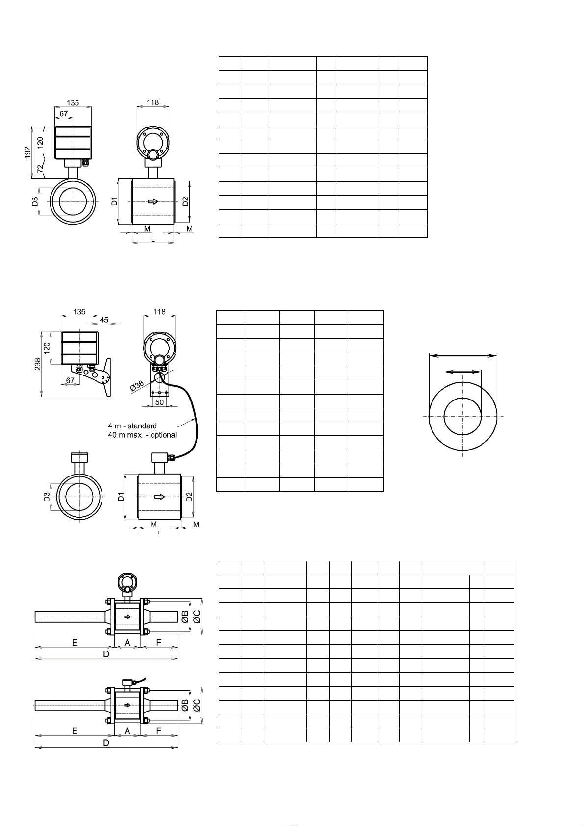
4.13. Mechanical installation of control head with the display. .................................... 7
4.14. Unflanged electromagnetic flowmeter dimensions ............................................. 8
4.15. Unflanged electromagnetic flowmeter gasket dimensions .................................. 8
4.16. Dimensions of unflanged electromagnetic flowmeter ......................................... 8
4.17. Flanged flowtube sensor dimensions ................................................................ 9
4.18. Dimensions of FG4000 electromagnetic flowmeter with threaded connection ..... 9
5. ptional temperature sensor location and installation ................... 10
5.1. Temperature sensor installation...................................................................... 10
5.2. Tube heat-insulation ...................................................................................... 10
5.3. Temperature sensor cables legth. .................................................................. 10
6. FG4000 electromagnetic flowmeter connection to power .............. 11
6.1. Power supply ................................................................................................. 11
6.2. Safety class ................................................................................................... 11
6.3. FG4000 electromagnetic flowmeter power supply fuse links. ........................... 11
6.4. liminating the most common problems arising during operation. .................... 11
7. Terminal bars, connectors and jumpers .......................................... 12
7.1. Terminal bars, connectors and jumpers .......................................................... 12
7.2. Connection of temperature sensors to optional thermometer module ............... 13
7.3. lectromagnetic flowmeter pulse outputs ........................................................ 14
7.4. pulse input.................................................................................................. 14
8. Interface modules and archiving module ........................................ 15
8.1. RS232 interface module ................................................................................. 15
8.2. 4- 20mA or 0- 10V analogue output modules with RS232 interface............... 15
8.3. RS485 interface module ................................................................................. 16
8.4. M-Bus interface module................................................................................. 16
8.5. RS232 interface module with two pulse inputs ................................................ 16
8.6. Archiving module ........................................................................................... 17
8.7. Communication protocols for data collection by FG4000 ................................. 18
9. Empty pipe detection ........................................................................ 21
9.1. Basic features ................................................................................................ 21
9.2. Settings of the detection ................................................................................. 21
10. Basic specification, display.............................................................. 22
10.1. FG4000 electromagnetic flow meter basic specifications ................................. 22
10.2. FG4000 flow meter display ............................................................................. 23
10.3. User counters in FG4000 flowmeter ............................................................... 25
10.4. FG4000 flowmeter operating modes ............................................................... 26
10.5. FG4000 firmware versions ............................................................................. 27
10.6. Setting menu structure ................................................................................... 27
11. rdering ............................................................................................ 31
12. Notes ................................................................................................. 32