English English
5
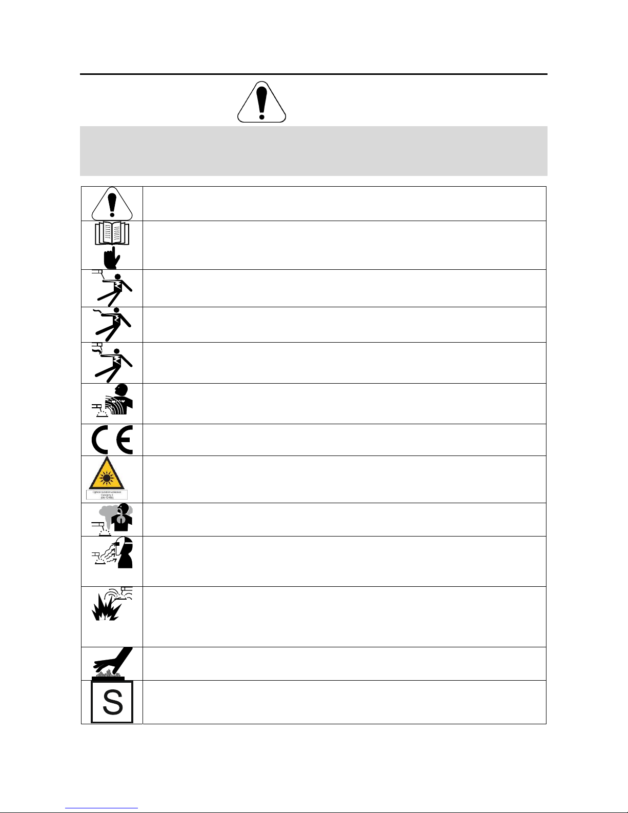
CYLINDER MAY EXPLODE IF DAMAGED: Use only compressed gas cylinders containing the
correct shielding gas for the process used and properly operating regulators designed for the gas and
pressure used. Always keep cylinders in an upright position securely chained to a fixed support. Do
not move or transport gas cylinders with the protection cap removed. Do not allow the electrode,
electrode holder, work clamp or any other electrically live part to touch a gas cylinder. Gas cylinders
must be located away from areas where they may be subjected to physical damage or the welding
process including sparks and heat sources.
The manufacturer reserves the right to make changes and/or improvements in design without upgrade at the same time
the operator’s manual.
Introduction
LGA Interface is an add-on module intended to be used
with Lincoln Electric Arclink welders such as Power
WaveR450 and S500,. The module attaches to the
front of a machine in place of a User Interface. The
LGA Interface add-on contains a Lincoln Electric
L16616 Anybus board with an HMS Anybus
CompactCom M30 module.. LGA works as a gate
between an industrial network and the welder’s internal
Arclink network. It also works as the welding sequencer
for the welder and is capable of storing up to 1000
welding jobs. A welding job contains all necessary
welding parameters: from PostFlow, to Striking,
Ramping up, Welding, Ramping down, Crater fill,
Burnback operation, and Post Flow.
Configuration of the job can be done in one of two
different ways, using the LGA Control Panel or through
the Power Wave Manager software. The jobs are saved
on the L16616 board in the LGA Interface module.
When replacing a LGA Interface module or this board,
the Jobs should be backed up first, and then restored
when the new module/board is installed.
The LGA Interface is designed for ease of configure
and use with a PLC. There are two modes of operation,
Job Mode and Job Mode with Parameter Inputs. Each
of these modes of operation requires that 12 bytes of
data be sent to and from the Master to the welder. In its
simplest implementation, Job Mode, all that is required
to initiate welding is to send over a valid Job Number
and then to set the Trigger input bit to true. All the
welding parameters are contained from the Job setup
parameters. With Job Mode with Parameters Inputs, the
weld state inputs are obtained from IO inputs from the
PLC interface to the welder. In this mode of operation,
the Master has direct control of the weld state welding
parameters and these inputs parameters can be
changed during the weld.
LGA is designed to work in different welding
configurations. The LGA will control turn on and off the
Wire Drive motor and Gas output automatically during
the welding sequence.
Installation and Operator Instructions
Read this entire section before installation or operation
of the machine.
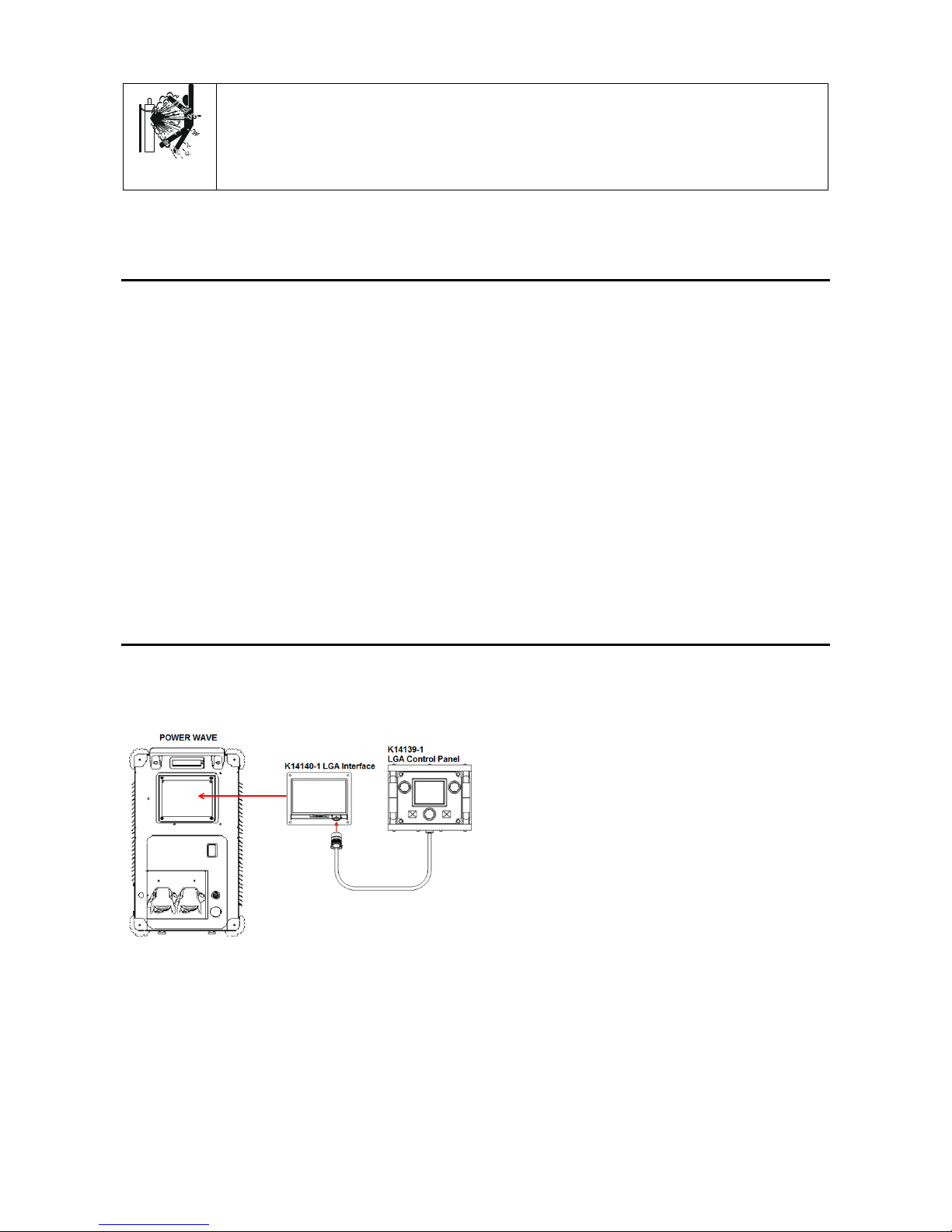
Connection Digram
Figure 1
Note: All welding parameters are stored in the LGA
Interface and it can work without LGA Control Panel
connected. It is recommended to connect/disconnect
LGA Control Panel when Power Source is switched off.
Connecting/disconnecting LGA Control Panel during
operation will stop welding process and restart the
system.
Requirements
A Robotic Wire Drive must be present or the Module
will go fatal with a 0x5211 (Required Object Not
Found), with an instance code of 1. A semi-
automatic wire drive will not work.
A Power Wave Control board (“G4800”, “G6683”, or
“L11088”) must be present or the Module will go
fatal with a 0x5211 (Required Object Not Found),
with an instance code of 2.
If an Autodrive SA or S is found, the Module will go
fatal with a 0x5611 (Arclink Bad Object).