Lincoln V2500 Series User manual

Domestic and International Service Manual
Digital Countertop Conveyor Oven
Series 2500
Consistency You Can Count On
Document #: LIN_EO_SM_DIGCT_S2500_DOM&INTL_4606010 – 07/21
Original Document
C US

Safety Notices
As you work on Lincoln equipment, be sure to pay close
attention to the safety notices in this manual. Disregarding
the notices may lead to serious injury and/or damage to the
equipment.
Throughout this manual, you will see the following types of
safety notices:
DANGER
Text in a Danger box alerts you to an eminent personal
injury situation. Be sure to read the Danger statement
before proceeding, and work carefully.
nWarning
Text in a Warning box alerts you to a potential personal
injury situation. Be sure to read the Warning statement
before proceeding, and work carefully.
,Caution
Text in a Caution box alerts you to a situation in which
you could damage the equipment. Be sure to read
the Caution statement before proceeding, and work
carefully.
Procedural Notices
As you work on Lincoln equipment, be sure to read the
procedural notices in this manual. These notices supply
helpful information which may assist you as you work.
Throughout this manual, you will see the following types of
procedural notices:
Important
Text in an Important box provides you with information
that may help you perform a procedure more efficiently.
Disregarding this information will not cause damage or
injury, but it may slow you down as you work.
NOTE: Text set off as a Note provides you with simple, but
useful, extra information about the procedure you are
performing.
Read These Before Proceeding:
DANGER
Do not install or operate equipment that has been
misused, abused, neglected, damaged, or altered/
modified from that of original manufactured
specifications.
nWarning
Improper installation adjustment, alteration, service
or maintenance can cause property damage, injury or
death. Read the instructions thoroughly before installing
or servicing this equipment.
nWarning
Authorized Service Representatives are obligated to
follow industry standard safety procedures, including,
but not limited to, local/national regulations for
disconnection / lock out / tag out procedures for all
utilities including electric, gas, water and steam.
nWarning
Never use a high-pressure water jet for cleaning or hose
down or flood interior or exterior of units with water. Do
not use power cleaning equipment, steel wool, scrapers
or wire brushes on stainless steel or painted surfaces.
,Caution
Maintenance and servicing work other than cleaning as
described in this manual must be done by authorized
service personnel.

Table of Contents
Document #: LIN_EO_SM_DIGCT_S2500_DOM&INTL_4606010 – 07/21 3
Section 1
General Information
Model Number Key ............................................................................................................7
Section 2
Installation
Exterior Dimensions – Series 2500 ...................................................................................9
Installation Requirements...............................................................................................10
Electrical Code Requirements......................................................................................................... 10
Spacing Requirements ...................................................................................................................... 10
Ventilation Requirements................................................................................................................. 10
Installation........................................................................................................................10
Electrical Grounding Instructions.................................................................................................. 11
Assembly Instructions .....................................................................................................11
Stacking Instructions .......................................................................................................12
Mounting Instructions .....................................................................................................12
Installation Checklist .......................................................................................................13
Checklist ................................................................................................................................................. 13
Section 3
Operation
Sequence of Operation....................................................................................................15
Power Supply........................................................................................................................................ 15
Control Box Auto Cool Down.......................................................................................................... 15
Main Fan Circuit ................................................................................................................................... 15
Heating Circuit...................................................................................................................................... 15
Oven Control......................................................................................................................................... 15
Conveyor Drive..................................................................................................................................... 15
Amber Light .......................................................................................................................................... 15
Section 4
Maintenance
Operator Maintenance.....................................................................................................17
Daily Cleaning ..................................................................................................................17
Weekly Cleaning...............................................................................................................17
Monthly Cleaning.............................................................................................................17
Conveyor Removal & Reinstallation ...............................................................................18
Finger Removal & Disassembly for Cleaning .................................................................19
Disassembly .......................................................................................................................................... 19
Disassemble Fingers for Cleaning ................................................................................................. 19
Reassembly............................................................................................................................................ 19
Preventive Maintenance..................................................................................................19
Section 5
Troubleshooting
Troubleshooting Guide....................................................................................................21

4 Document #: LIN_EO_SM_DIGCT_S2500_DOM&INTL_4606010 – 07/21
Table of Contents (continued)
Section 6
Controls
Operating Instructions ....................................................................................................25
Power-Up the Oven............................................................................................................................ 25
Change Belt Direction ....................................................................................................................... 25
Shutdown............................................................................................................................................... 25
Programming ...................................................................................................................26
Programming the Four Menu Preset Buttons........................................................................... 26
Programming the Manual Mode ................................................................................................... 26
Programming the Subset Menu..................................................................................................... 27
Section 7
Component Procedures
Oven Back .........................................................................................................................29
Oven Hi-Limit....................................................................................................................29
Thermocouple ..................................................................................................................29
Power Switch ....................................................................................................................29
Motor Capacitor ...............................................................................................................30
Main Fan............................................................................................................................30
Heating Element...............................................................................................................30
Air Pump ...........................................................................................................................30
Fan Motor..........................................................................................................................30
Conveyor ...........................................................................................................................31
Conveyor Sprockets .........................................................................................................31
Conveyor Motor................................................................................................................31
Transformer ......................................................................................................................31
Contactor ..........................................................................................................................32
Conveyor Bearings ...........................................................................................................32
Main Control .....................................................................................................................32
Proportional Controller ...................................................................................................32
Membrane.........................................................................................................................32
Solid State Relay...............................................................................................................32
Cooling Fan Thermostat...................................................................................................32
Cooling Fan Motor............................................................................................................32
Control Box Hi-Limit.........................................................................................................33
Time Delay Relay ..............................................................................................................33
Main Fan Relay or Dual Voltage Relay ............................................................................33
Voltage Monitoring Relay................................................................................................33
Air Pressure Switch...........................................................................................................33
Fuse Holder.......................................................................................................................33
DC Power Supply..............................................................................................................33
Section 8
Charts
Utility Specifications........................................................................................................35

Document #: LIN_EO_SM_DIGCT_S2500_DOM&INTL_4606010 – 07/21 5
Table of Contents (continued)
Section 9
Diagrams
Wiring Schematics............................................................................................................37
Model 2500 SN 1606100100720 to SN 2012100100663...................................................... 37
Model 2500 SN 2012100100664 and Above ............................................................................ 38
Models 2501, 2502............................................................................................................................. 39
Models 2504, 2510.............................................................................................................................. 40
Model 2505............................................................................................................................................ 41
Model 2507............................................................................................................................................ 42
Models 2508, 2509.............................................................................................................................. 43
Model 2512............................................................................................................................................ 44
Model 2514............................................................................................................................................ 45

6 Document #: LIN_EO_SM_DIGCT_S2500_DOM&INTL_4606010 – 07/21
Table of Contents (continued)
THIS PAGE INTENTIONALLY LEFT BLANK

Document #: LIN_EO_SM_DIGCT_S2500_DOM&INTL_4606010 – 07/21 7
Model Number Key
Example: 2501-000-U-0001620
25 01 000–––U 00 0 1620
MODEL
(i.e. Digital Countertop)
INDICATES VOLTAGE
(i.e. 208V, 1 phase, 60 Hz)
LANGUAGE CODE
CUSTOM CONFIGURATION CODE
(i.e. General Market)
AGENCY CODE
(i.e. US & Canada compliance)
FINGER SETUP
PLATFORM SIZE
Language Code
Code Language Country
0 English Dom. & Int. Default
B French CE – France/Luxembourg
C German CE – Germany
D Italian CE – Italy
E Spanish CE – Spain
F English CE – UK/India/Africa/Hungary
G Spanish Mexico/Latin America
H Portuguese CE – Portugal
I Not Used ---
J Danish CE – Denmark
K Dutch & French CE – Belgium
L Dutch CE – Netherlands
M Greek CE – Greece
N Finnish CE – Finland
O Restricted ---
P Norwegian CE – Norway
Q English Japan
R Swedish CE – Sweden
S English Australia
T Mandarin China
U Restricted ---
V English Pacific Rim/Korea
W English Middle East/Africa
X Not Used ---
Y Not Used ---
Z Not Used ---
Agency Code
Code Agency
N No agency
E CE & RoHS compliance combined
U US & Canada compliance only
A Advantage style oven
B Australia AGA
Section 1
General Information

8 Document #: LIN_EO_SM_DIGCT_S2500_DOM&INTL_4606010 – 07/21
General Information Section 1
THIS PAGE INTENTIONALLY LEFT BLANK

Document #: LIN_EO_SM_DIGCT_S2500_DOM&INTL_4606010 – 07/21 9
Exterior Dimensions – Series 2500
A
B
C
E
D
F
G
H
I
J
A* B** C D E F G*** H I J
Inches
(mm)
51.125
(1298.6)
31.10
(789.9)
20.50
(520.7)
17.9375
(455.6)
31.875
(809.6)
18.25
(463.6)
49.75
(1263.7)
31.25
(793.8)
18.9375
(481.0)
27.50
(698.5)
* A dimension pertains to a unit with standard conveyor and 12" (304 mm) take-off shelves included on each end.
** B dimension pertains to a unit with standard length conveyor.
*** G dimension pertains to a unit with an extended conveyor only.
NOTE: Specifications subject to change without notice.
NOTE: Do not install this (these) oven(s) in any area with an ambient temperature in excess of 95°F (35°C). Doing so will cause
damage to unit.
Section 2
Installation
A
B
C
E
D
F
G
H
I
J

10 Document #: LIN_EO_SM_DIGCT_S2500_DOM&INTL_4606010 – 07/21
Installation Section 2
Installation Requirements
DANGER
All utility connections and fixtures must be maintained in
accordance with local and national codes.
ELECTRICAL CODE REQUIREMENTS
nWarning
This appliance must be grounded and all field wiring
must conform to all applicable local and national
codes. Refer to rating plate for proper voltage. It is the
responsibility of the end user to provide the disconnect
means to satisfy the authority having jurisdiction.
nWarning
This equipment must be positioned so that the plug is
accessible unless other means for disconnection from
the power supply (e.g., circuit breaker or disconnect
switch) is provided.
,Caution
In order to avoid a hazard due to inadvertent resetting of
the thermal cutout, this appliance must not be supplied
through an external switching device, such as a timer or
connected to a circuit that is regularly switched on and
off by the utility.
IN USA: When installed, this appliance must be electrically
grounded and its installation must comply with the
National Electric Code, ANSI-NFPA 70, latest edition, the
manufacturers’installation instructions, and applicable local
municipal building codes.
IN CANADA: All electrical connections are to be made in
accordance with CSA C22.21 latest version – Canadian
Electrical Code Part 1 and/or local codes.
ALL OTHER COUNTRIES: Local electrical codes will prevail.
1. Strain relief is provided with each oven. International
Dealer/Distributors provide applicable power cord/
plug for each customer.
2. All pole disconnection switch must have 3 mm open
contact distance.
3. To prevent electrical shock, an equal potential bonding
ground lug is provided in the back. This allows the oven
to be connected to an external bonding system.
4. If used as double-stack and each oven has its own
disconnection switch, all switches should be close
together.
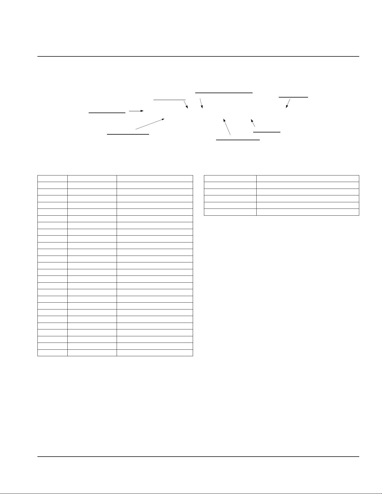
SPACING REQUIREMENTS
The oven must have 6 inches (152 mm) of clearance from
combustible surfaces. In case other equipment is located
on the right side of oven, a minimum clearance of 24 inches
(609 mm) is required from that equipment.
FOR ALL OVENS: A 24-inch (609 mm) clearance at the rear of
the oven must be obtainable for service access.
VENTILATION REQUIREMENTS
Local codes prevail. These are the authority having
jurisdiction as stated by the NATIONAL FIRE PROTECTION
ASSOCIATION, INC. in NFPA 96 latest edition.
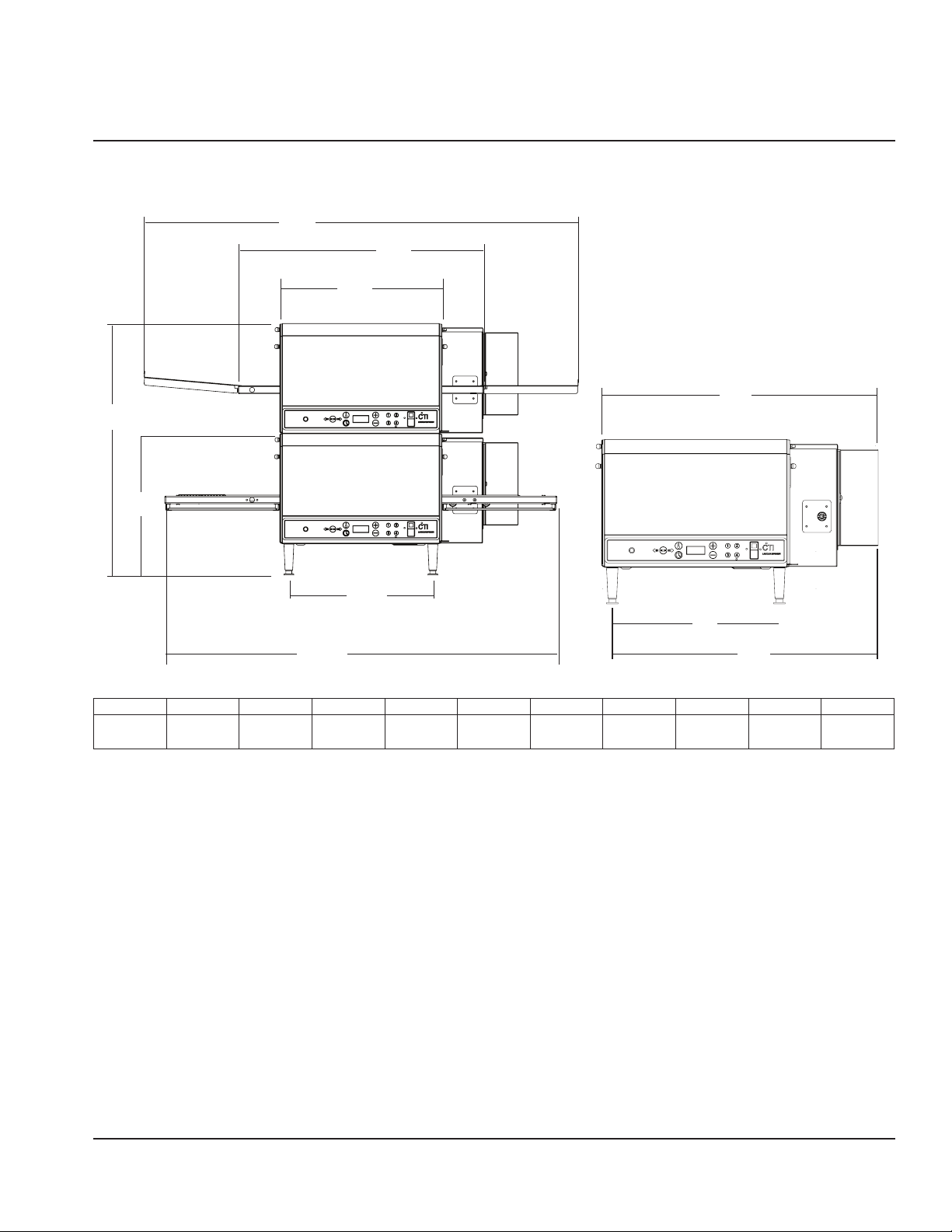
Installation
The instructions that follow are intended as a guide for
preparing for the installation of the Countertop Conveyor
oven. First and foremost, each crate should be examined
before signing the Bill of Lading to report any visible
damage caused during shipment in transit, and to account
for the proper number of crates.
IF THERE IS APPARENT DAMAGE:
UNITED STATES AND CANADA: Arrangements should
be made to file a claim against the carrier, as Interstate
Commerce Regulations require that the consignee initiate
a claim.
ALL SHIPMENTS TO OTHER COUTRIES: Freight terms will be
developed and extended on an individual basis.
Proper and secure storage facilities should be arranged for
the oven(s). If necessary, protect it from outdoor or damp
conditions at all times before installation.

Document #: LIN_EO_SM_DIGCT_S2500_DOM&INTL_4606010 – 07/21 11
Section 2 Installation
ELECTRICAL GROUNDING INSTRUCTIONS
nWarning
Domestic
As it pertains to domestic model units, this appliance
is equipped with a three-prong (grounding) plug for
your protection against shock hazard and should be
plugged directly into a properly grounded three-prong
receptacle. Do not cut or remove the grounding prong
from this plug.
nWarning
International (CE)
This appliance must be properly grounded at time
of installation. Failure to ensure that this equipment
is properly grounded can result in electrocution,
dismemberment or fatal injury.
nWarning
If the supply cord appears to be damaged, do not
attempt to operate unit. Contact a service agent or
qualified electrician to repair.
Assembly Instructions
Install legs as shown.
,Caution
Legs MUST be installed to ensure proper operation!
Failure to do so will result in damage to unit and denied
warranty claims.
,Caution
Oven must be operated on an approved base only.
When utilizing a double-stack configuration of ovens,
the bottom unit must always be mounted on the legs
provided.
,Caution
Before applying power to the oven, check to ensure
that the finger assemblies and air duct panels (upper
and lower) are properly seated and have not become
dislodged during shipment.
Front of Finger
Assembly Properly
Installed Cut-away view of interior baking
chamber noting Finger and
Plenum installation

12 Document #: LIN_EO_SM_DIGCT_S2500_DOM&INTL_4606010 – 07/21
Installation Section 2
Stacking Instructions
FOR SINGLE AND DOUBLE STACK UNITS
Important
When stacking ovens, be sure to remove the bottom
flue cap from top oven.
Upper
Oven
Lower
Oven
NOTE: When utilizing a double-stack configuration, stack
the ovens so that the small foot on the top oven fits into the
indentation on the top of the bottom oven.
,Caution
If you utilize a double-stack configuration, please note
that each oven has its own disconnect switch. Make
sure that all switches are in the OFF position before
beginning maintenance or cleaning.
,Caution
If stacking configuration consists of analog (1300 Series),
square top digital (2500 Series), or angled top digital
(2500 Series) units, always stack as illustrated. Incorrect
stacking arrangement may damage both ovens!
Mounting Instructions
Position the oven on the countertop and carefully mark
the position of the rear legs. Remove the oven from the
countertop and position the mounting rings so that the
large (center) hole is where the legs of the oven were
marked. Mark the position of the two small holes and
remove the mounting rings.
When installing on a heavy stainless steel or wood
countertop, use the four 3/16" x 9/32" drive rivets. Use a
0.218" diameter drill (7/32") and drill at least 1/2" into a
wood countertop or all the way through a steel countertop
so that the rear legs are in the large holes in the mounting
ring.
Position washers to rear legs, anchor them to
countertop using screws provided.
,Caution
Install this unit in the most convenient locations for
ease of cleaning, maintenance, and general operation.
Avoid installing in locations with drafts, close proximity
to grease or vapor-producing appliances or other high-
ambient heat equipment.

Document #: LIN_EO_SM_DIGCT_S2500_DOM&INTL_4606010 – 07/21 13
Section 2 Installation
Installation Checklist
DANGER
Check all wiring connections, including factory terminals,
before operation. Connections can become loose during
shipment and installation.
CHECKLIST
Are the correct clearances maintained?
Is the bottom unit on legs?
Are legs fastened to the counter-top with included
hardware?
If stacked, is the top unit without legs?
If stacked, is the flue cap removed between ovens?
Is the unit level?
Is the unit grounded?
Have all wiring connections including the factory
connections been checked?
Has the supply voltage been tested and verified it
matches the name plate voltage?
Are the finger assemblies correctly installed and
positioned?
Is the finger configuration written down?
Has the unit been tested for correct operation?
Has the owner been instructed in the correct operation
of the unit?

14 Document #: LIN_EO_SM_DIGCT_S2500_DOM&INTL_4606010 – 07/21
Installation Section 2
THIS PAGE INTENTIONALLY LEFT BLANK

Document #: LIN_EO_SM_DIGCT_S2500_DOM&INTL_4606010 – 07/21 15
Sequence of Operation
POWER SUPPLY Electrical Power is supplied to the oven by a three conductor cord set.
• Black conductor is HOT.
• White conductor is HOT.
• Green conductor is ground.
Line voltage is supplied through the fuses (F1, F2) and line one (L1) through the manual
resettable control box high limit (T1) to the ON/OFF switch, the Cooling Fan Thermostat (T2), the
Cool Down Timer (TD), and to the Main Fan Relay (R2).
NOTE: 50Hz Ovens with 3PH have a third conductor that is HOT and it is only supplied to the
heating circuit.
CONTROL BOX AUTO
COOL DOWN
The cooling fan thermostat is connected to the axial fan that cools the control box. Line two (L2)
connects to the other side of the Control Box Cooling Fan motor, bypassing the ON/OFF switch.
The thermostat closes at 120°F, cycling the fan, keeping the control box below 120°F.
MAIN FAN CIRCUIT Upon activating the ON/OFF switch, power is supplied to the Cool Down Timer (TD) through the
timer (TD) to the Main Fan Relay (R2), through the relay (R2) to power the Main Fan (M1).
HEATING CIRCUIT The heating contactor then closes, supplying line voltage to the SSR for the heater. Line voltage
is then supplied to the element through the SSR as needed to maintain set point temperature.
OVEN CONTROL Upon closing the ON/OFF switch, the transformer is supplied line voltage and then
supplies 24VAC to the control board and controls the conveyor motor. The control reads
the thermocouple and cycles the SSR to the heater to maintain set point temperature. The
control board also reads the input from the keypad to make adjustments for cook time and
temperature.
CONVEYOR DRIVE The control board transformer’s (XR) secondary supplies 24 VAC to the control board (CNTR). The
conveyor control supplies voltage to the conveyor motor (M3). 5-12 VAC is supplied to the motor
(M3) through 4 wires (2 sets, A+ A- & B+ B-).
AMBER LIGHT (model 2504 Australia only) T4 & T5 thermostats are (behind front panel). T4 is a normally closed
thermostat and opens at 175°F (79°C) and resets automatically at 144°F (62°C). When open
it stops 5V DC to coil of SSR. T5 is a normally open thermostat and closes at 140°F (60°C) and
will open automatically at 120°F (49°C), when closed will cause the Amber Light to illuminate
indicating dirty filter.
Section 3
Operation

16 Document #: LIN_EO_SM_DIGCT_S2500_DOM&INTL_4606010 – 07/21
Operation Section 3
THIS PAGE INTENTIONALLY LEFT BLANK

Document #: LIN_EO_SM_DIGCT_S2500_DOM&INTL_4606010 – 07/211 17
Operator Maintenance
nWarning
Disconnect power supply before servicing or cleaning
this oven. Safeguard power so it cannot be accidentally
restored. Failure to do so could result in dismemberment,
electrocution, or fatal injury.
The Lincoln Countertop Impinger® Oven contains electrical
components. Before cleaning the oven, switch off and
disconnect the oven from the electrical supply.
No electrical components should be subjected to moisture.
Therefore, it is important the oven is wiped down carefully.
NEVER throw buckets of water over the oven or subject it to
pressure washing from a hose or a pressure spray. If water
or other liquid is spilled on the oven, make sure that none
has entered the control box area before switching on. If in
doubt, call your service company.
To achieve the maximum efficiency of the oven, it is
necessary to keep it clean. The frequency listed is only the
factory’s recommendation. Your use and type of products
will actually determine the frequency of cleaning.
,Caution
Oven must be cool. Do not use power-cleaning
equipment, steel wool, or wire brushes on stainless steel
surfaces.
Daily Cleaning
1. Clean exterior surfaces of the oven by wiping it down
with a mild detergent and clean water, or a commercial
stainless steel cleaner.
2. Clean the interior by sweeping up all loose particles,
then wash with a mild detergent solution and rinse
with clean water.
3. Clean the conveyor belt by wiping with a clean, water-
dampened cloth to remove any baked on crust or food
product.
,Caution
Do not use caustic or alkaline base cleaner on interior
of oven. This will ruin the aluminized finish of the oven
interior. On exterior of oven, removal of deposits of
baked-on splatter, oil, grease, or light discolorations may
be removed with any of several commercial cleaners.
Consult with your local supplier.
nWarning
When using cleaning solutions, be sure they meet local
and national health standards.
Weekly Cleaning
1. Remove conveyor, disassemble and clean. See
Conveyor Removal section for more information.
2. Remove fingers, disassemble and clean. See Finger
Removal section for more information.
Monthly Cleaning (model 2504 Australia only)
1. Remove grease filter at front panel.
2. Remove grease filter at control box cover.
NOTE: Grease filters are dishwasher only, no friction or
abrasion cleaning. Clean both filters when the indicator
light turns on or every month whichever comes first.
Section 4
Maintenance
Filters out

18 Document #: LIN_EO_SM_DIGCT_S2500_DOM&INTL_4606010 – 07/21
Maintenance Section 4
Conveyor Removal & Reinstallation
,Caution
Conveyor and belt may be hot!
1. Remove extension shelves (if applicable).
2. Push coupling away from drive lugs.
Remove conveyor from oven cavity.
3. Reassemble in reverse order.
4. Install extension shelves (if applicable).

Document #: LIN_EO_SM_DIGCT_S2500_DOM&INTL_4606010 – 07/21 19
Section 4 Maintenance
Finger Removal & Disassembly for Cleaning
DISASSEMBLY
1. Remove 1/4-20 thumbscrews (2 per panel) then pull
back the panel.
2. Lift panel off lower retaining tabs.
3. Lift finger assembly to clear hanger on front wall of
oven. Then slide to the rear and swing out.
4. Remove finger assembly from oven.
DISASSEMBLE FINGERS FOR CLEANING
Slide finger cover from housing. Lift out inner columnating
plate.
Columnating
Plate
Orice
Panel
REASSEMBLY
1. Reassemble in reverse order.
NOTE: Check to ensure that the holes in the columnating
plate are lined up with the holes in the orifice panel.
2. Reinstall fingers in the oven. Be sure that they are fully
seated over the plenum flanges and the holes are
pointing toward the conveyor.
3. Reinstall cover panels (see Disassembly).
Fingers (configuration) may be different in each section
of oven so verify part numbers stamped into parts prior
to reassembly.
Preventive Maintenance
Although this oven has been designed to be as trouble-
free as possible, periodic preventive maintenance is
essential to maintain peak performance. It is necessary to
keep the motors, fans, and electronic controls free of dirt,
dust and debris to ensure proper cooling. Overheating
is detrimental to the life of all components mentioned.
The periodic intervals for preventive cleaning may
vary greatly depending on the environment in which
the oven is operating. You must discuss the need for
preventive maintenance with your Authorized Service
Agency to establish a proper program. If there are any
questions that the service agency cannot answer, please
contact the KitchenCare Technical Service Department at
(844) 724-2273.

20 Document #: LIN_EO_SM_DIGCT_S2500_DOM&INTL_4606010 – 07/21
Maintenance Section 4
THIS PAGE INTENTIONALLY LEFT BLANK
This manual suits for next models
12
Table of contents
Other Lincoln Commercial Food Equipment manuals
Popular Commercial Food Equipment manuals by other brands

Mibrasa
Mibrasa ROBATAYAKI RM 60 instruction manual

Duke
Duke FWM3-22 Operator's and service manual

Vollrath
Vollrath Stoelting E131-I2 Operator's manual

Polar Electro
Polar Electro CM287 instruction manual

Moffat
Moffat Vgen V2 Series OPERATING & SERVICE MANUAL

Allure
Allure Melanger 4-0.25-230-50-A owner's manual