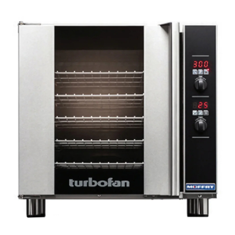
turbofan 30D Series User manual

Service Manual
E33D5
(Digital Operation)
30DSERIES
E33D5 Service Manual © Copyright Moffat Ltd. 6 May 2016
Revision 1 - Amdt 5
Service Manual
E33D5
(Digital Operation)
30DSERIES

The reproduction or copying of any part of this manual by any means whatsoever is strictly forbidden unless authorized previously in writing
by the manufacturer.
In line with policy to continually develop and improve its products, Moffat Ltd. reserves the right to change the specifications and design
without prior notice.
© Copyright Moffat Ltd. May 2016.
MANUFACTURED BY
Moffat Limited
Rolleston 7675
New Zealand
INTERNATIONAL CONTACTS
AUSTRALIA
Moffat Pty Limited
Web: www.moffat.com.au
E.Mail: [email protected]
Main Office: (tel) +61 (03) 9518 3888
(fax) +61 (03) 9518 3838
Service: (tel): 1800 622 216
Spares: (tel): 1800 337 963
Customer Service: (tel): 1800 335 315
(fax): 1800 350 281
CANADA
Serve Canada
Web: www.servecanada.com
E.Mail: [email protected]
Sales: (tel): 800 551 8795 (Toll Free)
Service: (tel): 800 263 1455 (Toll Free)
NEW ZEALAND
Moffat Limited
Web: www.moffat.co.nz
E.Mail: [email protected]
Main Office: (tel): 0800 663328
UNITED KINGDOM
Blue Seal
Web: www.blue-seal.co.uk
E.Mail: [email protected]
Sales: (tel): +44 121 327 5575
(fax): +44 121 327 9711
Spares: (tel): +44 121 322 6640
(fax): +44 121 327 9201
Service: (tel): +44 121 322 6644
(fax): +44 121 327 6257
UNITED STATES
Moffat
Web: www.moffat.com
Sales: (tel): 1800 551 8795 (Toll Free)
(tel): +1 336 661 1556
(fax): +1 336 661 9546
Service: (tel): 866 673 7937 (Toll Free)
(tel): +1 366 661 1556
(fax): +1 336 661 1660
REST OF WORLD
Moffat Limited
Web: www.moffat.co.nz
E.Mail: [email protected]
E33D5 Service Manual © Copyright Moffat Ltd. 6 May 2016
Revision 1 - Amdt 5

Contents List
E33D5 Service Manual © Copyright Moffat Ltd. 06 May 2016.
Revision 1 - Amdt 5
E33D Turbofan Convection Oven.
Model Numbers Covered in this Manual
E33D5 - Turbofan Oven - - 5 Tray Convection Oven.
1. Specifications ....................................................................................................2
2. Installation ........................................................................................................3
Installation Requirements
Unpacking
Location
Clearances
Stand Mounted Ovens
Electrical Connection
Water Connection
Positioning and Levelling of Oven
Initial Start-Up
Commissioning
3. Operation...........................................................................................................5
Oven Control Panel - E33D Series (Digital Controller)
Changing User Parameters
Table of User Settings
4
.
Error Messages and Faults ................................................................................7
Controller Fault Codes
5. Parts Replacement ............................................................................................8
5.1 Access
5.2 Replacement
5.3 Adjustment and Calibration
6
.
Controller Programming..................................................................................14
Controller Parameters
7. Circuit Schematics ...........................................................................................17
8. Wiring Diagrams..............................................................................................18
9. Exploded Parts Listings ...................................................................................19
ALL INSTALLATION AND SERVICE REPAIR WORK MUST BE CARRIED OUT BY QUALIFIED PERSONS ONLY.
IMPROPER INSTALLATION, ALTERATION, ADJUSTMENT, MAINTENANCE OR SERVICE MAY CAUSE PROPERTY
DAMAGE, INJURY OR DEATH.
ENSURE SUPPLY IS SWITCHED OFF BEFORE SERVICING.
ALWAYS TEST AFTER SERVICE REPAIRS
WARNING:

1 Specifications
2
E33D5 Service Manual © Copyright Moffat Ltd. 06 May 2016.
Revision 1 - Amdt 5
E33D5 Oven
Oven Power Ratings
230 - 240V, 50Hz or 60Hz, 6.0kW, 1P+N+E.
220V, 50Hz or 60Hz, 6.0kW, 1P+N+E.
220 - 240V, 60Hz, 6.0kW, 1P+N+E.
208V, 60Hz, 5.8kW, 1P+N+E.
Tray Capacity
5 Shelf - 1/1 GN Pan.
5 Shelf - 13” x 18” Bun Pan.
5 Shelf - 12” x 20” Steam Pan.
Tray Spacing 31/3” / 85mm.
Max Water Pressure 80psi / 550kPa.
Water Connection Size 3/4” GHT / 3/4” BSP.

Installation 2
3
E33D5 Service Manual © Copyright Moffat Ltd. 06 May 2016.
Revision 1 - Amdt 5
Installation Requirements
Unpacking
1. Remove all packaging and transit protection including
all protective plastic coating from the exterior stainless
steel panels.
2. Check the oven and supplied parts for damage. Report
any damage immediately to the carrier and distributor.
3. Check that the following parts have been supplied with
your oven:-
4 x Leg Adjustable.
Brass Adaptor.
Rubber Washer.
4. Report any deficiencies to the distributor who supplied
your oven.
5. Securely fit the 4 legs supplied with the oven.
6. Check that the available electrical supply is correct to
that shown on the Technical Data Plate located on the
front right hand side panel.
Refer to ‘Specifications’ section, ‘Oven
Specifications Tables’.
Location
1. Position the oven in its approximate working position.
2. The unit should be positioned so that the control panel
and oven shelves are easily reachable for loading and
unloading.
Clearances
To ensure correct ventilation for the motor and controls,
the following minimum installation clearances are to be
adhered to:-
Rear 50mm / 2”.
Left-hand side 50mm / 2”.
Right-hand side 75mm / 3”.
CLEARANCE FROM SOURCE OF HEAT.
A minimum distance of 300mm (12”) from appliance
sides is required.
NOTE: Fixed installations require at least 500mm - 20”
clearance at right hand side of oven for
service access.
Stand Mounted Ovens
For ovens that are to be mounted to a stand, the oven feet
are used to level the oven on the stand. Refer to the
instructions supplied with separately ordered stands for
mounting details.
Important:
The vent located on the top of the oven must NOT be
obstructed.
Important:
Installation shall comply with local electrical, health and safety requirements.
It is most important that this oven is installed correctly and that oven operation is correct before use.
If you have any questions regarding the proper installation and / or operation of this oven, please contact your local
Turbofan distributor.
Technical Data Plate - Location.
USA / Canada Only)
Oven Vent Location

2 Installation
4
E33D5 Service Manual © Copyright Moffat Ltd. 06 May 2016.
Revision 1 - Amdt 5
Electrical Connection
Each oven should be connected to an adequately protected
power supply with an appropriate three wire power cord.
An isolation switch must be mounted adjacent to, but not
behind the oven and must be readily accessible to the
operator. This switch must be clearly marked and readily
accessible in case of fire.
Check the electricity supply is correct to as shown on the
Technical Data Plate on the front right hand corner of the
oven side panel.
NOTE: All electrical connections must only be carried
out by a suitably qualified person.
1. Remove oven right hand side panel.
2. Bring the supply cable up through the grommet at the
back of oven and through the compression gland on the
electrical switchgear panel.
3. Connect the mains supply to the appropriately marked
terminals on the terminal block.
Water Connection - Optional -
(Not required for Main Oven Operation)
1. If the manual addition of water into the oven for
humidification or steaming effect on baked product is
required, the unit’s water con-
nection can be used.
2. Tighten the 2 screws securing
the water connection to the rear
of the oven. (These have
purposely been left loose to
prevent damage to the water
connection during transit).
3. A cold water supply should be fitted to the water inlet
(¾” BSP hose connection) which is located on the rear
of the right hand side of the oven.
4. Connect to the water supply.
- Max Inlet Pressure 80psi / 550kPa.
5. Turn ‘On’ the water supply and check for leaks.
This oven must be earthed / grounded.
Warning
Tighten Screws.
Positioning and Levelling of Oven
1. Correctly locate the oven into its final operating position
and using a spirit level, adjust the oven feet so that the
oven is level and at the correct height.
Initial Start-Up
Before using the new oven;
1. For first time use of the oven, operate the oven for
about 1 hour at 200°C / 400°F to remove any fumes or
odours which may be present.
2. Please refer to the Operation Section of this manual for
details on how to correctly operate and shutdown the
oven.
Commissioning
Before leaving the new installation;
Check the oven functions in accordance with the
operating instructions specified in the ‘Operation’
section of this manual.
Ensure that the operator has been instructed in the areas
of correct operation and shutdown procedure for the
appliance.
NOTE: If it is not possible to get appliance to operate
correctly, turn Off power supply at mains
supply and contact supplier of this appliance.

Operation 3
5
E33D5 Service Manual © Copyright Moffat Ltd. 06 May 2016.
Revision 1 - Amdt 5
Oven Control Panel - E33D Series (Digital Controller)
For detailed operation instructions please refer to the User Manual supplied with your E33D oven.
Temperature Display -
Shows the pre-set chamber
temperature.
When used with the ‘Temperature’ key, display
shows actual oven temperature for 5 seconds.
Shows Cooking Modes and Error Codes.
Steam Key and LED -
Activates the ‘Steam Mode’.
Temperature Adjustment Control
Time Display -
Shows cook time in full minutes only
from 180 - 1, and in seconds for the final minute
only.
NOTE; In Core Temp Mode, the display
shows ‘CP’ and Core Temperature
of item being cooked.
On / Off / Key and LED
Press ‘On / Off’ key once to turn the oven
‘On’.
Press and hold ‘On / Off’ key for 2 se-
conds to turn the oven ‘Off’.
Time Adjustment Control.
NOTE; In Core Temp Mode, Timer Knob is
used to set Core Probe Temperature.
Programming Key and LED -
Used to enter the ‘Programming’ mode.
Temperature Key and LED -
Shows actual oven temperature for 5
seconds on the Temperature Display,
LED ‘On’ when heating.
LED flashes when showing actual temperature.
NOTE; In Core Temp Mode, this key is used
to display Actual Oven and Core
Probe temperatures.
Fan Lo/High Speed Key and
LED -
Switches oven fan from high to low
speed. LED is ‘On’ when fan is in Low Speed
mode.
Start / Stop Key and LED
The ‘Start / Stop’ key is used to control
the following functions:-
Cancelling Buzzer (All Modes).
Starting Core Temp Mode (Core Temp Mode).
Starting Timer (Manual Mode).
Resetting Timer (Manual Mode).
Starting Program (Program Mode).
Cancelling Program (Program Mode).
Core Probe Connection Point.

3 Operation
6
E33D5 Service Manual © Copyright Moffat Ltd. 06 May 2016.
Revision 1 - Amdt 5
Changing User Parameters
With the Oven in ‘Stand-By’ Mode:-
1. ENTER THE OPERATOR PARAMETER MODE.
Press 'Steam' and 'Start / Stop' buttons together.
‘Upper’ Display will show ‘PAS’.
The ‘Lower’ Display will flash.
2. SET PASSWORD.
Rotate ‘Timer Control’ to set password;
(123) (Operator Password).
Press ‘Fan Lo’ key to confirm password.
‘Upper’ Display will show one of the Parameter Codes.
‘Lower’ Display will show value of the parameter.
3. SETTING THE PARAMETERS.
Rotate ‘Timer Control’ to parameter required.
Press ‘Fan Lo’ key to confirm parameter. ‘Upper Display’ will flash.
While ‘Time’ display is flashing, rotate ‘Timer Control’ to
select value required.
Press ‘Fan Lo’ key to confirm value. Lower Display will stop flashing.
4. EXITING THE PARAMETER MODE.
Press ‘On-Off’ button, to return to ‘Stand-By’ mode.
Table of User Settings
Parameter
Number Description Default
Setting
Oven Pre-Heat; - (Automatic pre-heat temperature on oven start-up).
In ‘User Settings’ the temperature setting can be changed to user preference.
Setting Range, 60 - 260°C / 140 - 500°F.
150ºC
(325ºF)
Buzzer Volume - In ‘User Settings’, the buzzer volume can be changed to user preference.
Setting Range Levels, 0 -10. 5
Program Pre-Heating Ready Condition; - This setting allows for pre-heating ‘Ready’
temperature in ‘Program Mode’, mode to be set higher than the Program Set Temperature.
Setting Range for Pre-Heat above Set Point is, 0-30°C / 0-30°F.
0

Error Messages and Faults 4
7
E33D5 Service Manual © Copyright Moffat Ltd. 06 May 2016.
Revision 1 - Amdt 5
Fault Code Cause
Door Open.
Door Microswitch, open circuit.
Err 001
Oven Temperature Probe Fault,
- Open Circuit - check temperature probe connection PT1 on board.
- Short Circuit - Probe damaged, replace probe.
- Probe value is outside the conversion range.
Err 003 Motor overload activated / tripped.
dor
Controller Fault Codes

5 Parts Replacement
8
E33D5 Service Manual © Copyright Moffat Ltd. 06 May 2016.
Revision 1 - Amdt 5
5.1 Access
5.1.1 Control Panel....................................................................................................................... 9
5.1.2 LH & RH Side Access Panels ................................................................................................. 9
5.2 Replacement
5.2.1 Controller............................................................................................................................ 9
5.2.2 Encoder .............................................................................................................................. 9
5.2.3 Door Reed Switch ...............................................................................................................10
5.2.4 Door Magnet ......................................................................................................................10
5.2.5 Temperature Probe.............................................................................................................10
5.2.6 Cooling Fan........................................................................................................................10
5.2.7 Lighting Fuse Holder ...........................................................................................................10
5.2.8 Oven Lamp Assembly..........................................................................................................10
5.2.9 Transformer .......................................................................................................................11
5.2.10 Overtemp...........................................................................................................................11
5.2.11 Capacitor ...........................................................................................................................11
5.2.12 Water Solenoid...................................................................................................................11
5.2.13 Fan Motor ..........................................................................................................................11
5.2.14 Heating Element .................................................................................................................11
5.2.15 Contactor...........................................................................................................................11
5.2.16 Door Inner Glass ................................................................................................................12
5.2.17 Door..................................................................................................................................12
5.2.18 Door Hinge ........................................................................................................................12
5.2.19 Door Pivot..........................................................................................................................12
5.2.20 Door Handle.......................................................................................................................12
5.2.21 Door Locking Dog ...............................................................................................................12
5.3 Adjustment & Calibration
5.3.1 Temperature Calibration......................................................................................................13
5.3.2 Adjust Door for Correct Alignment........................................................................................13
5.3.3 Door Locking Dog Adjustment..............................................................................................13
5.3.4 Door Switch / Magnet Adjustment ........................................................................................13

Parts Replacement 5
9
E33D5 Service Manual © Copyright Moffat Ltd. 06 May 2016.
Revision 1 - Amdt 5
5.1 Access 5.2 Replacement
5.2.1 Controller
1. Remove control panel (refer 5.1.1).
2. Disconnect cables (7).
3. Undo securing nuts (8) 7mm, 9/32”.
5.2.2 Encoder
1. With control panel
removed from the
oven, remove control
knob from control
panel.
2. Disconnect encoder
plug from digital
control board.
3. Remove oven controller
if necessary.
4. Remove encoder from the control panel by removing
the two securing screws.
NOTE:
On Units up to Serial No. 798526, the Encoders may
not be fitted with a Stop Plate. When replacing the
Encoder, the Stop Plate and Control Knob supplied
in the kit, should be fitted.
On Units from Serial No. 798527, the Encoders are
fitted with a Stop Plate. This Stop Plate is secured
with the 2 Encoder securing screws as shown
below.
5.1.1 Control Panel
1. Remove screw on
underside of control
panel.
2. Lift panel up to
unhook at top.
5.1.2 LH & RH Side Access Panels
1. Remove 2 screws on
lower corners of side
panel.
2. Pull bottom of panel
out and away from
bottom of oven.
3. Pull down on panel to
remove.
Screw
Securing Screws
Securing Nuts (qty 8)
Securing
Screws
Encoder
Stop Plate
From Ser No. 798527
Control
Knob

5 Parts Replacement
10
E33D5 Service Manual © Copyright Moffat Ltd. 06 May 2016.
Revision 1 - Amdt 5
5.2.3 Door Reed Switch
1. Remove control panel (refer 5.1.1).
2. Unscrew and remove 2 screws securing reed switch and
remove reed switch.
3. Disconnect 2 wires from reed switch to control panel.
4. Replace reed switch and refit in reverse order.
5.2.4 Door Magnet
1. Unscrew 2 screws on underside of door and remove
magnet bracket with magnet attached.
2. Unscrew 2 nuts securing magnet to magnet bracket,
remove magnet.
3. Replace magnet and refit in reverse order.
5.2.5 Temperature Probe
1. Remove control panel
(refer 5.1.1).
2. Disconnect the
temperature probe
cable from controller.
3. Remove RH side oven
rack.
4. Undo temperature
probe bracket screw.
5. Withdraw probe and cable through oven cavity.
6. Replace temperature probe and refit in reverse order.
5.2.6
Cooling
Fan
1. Remove RH side panel
(refer 5.1.2).
2. Remove screws (2).
3. Rotate LH side of
cooling fan inwards to
remove.
4. Replace cooling fan and
refit in reverse order.
5.2.7 Lighting Fuse Holder
1. Remove RH side panel
(refer 5.1.2).
2. Remove Cooling Fan
(refer 5.2.6).
3. Remove wires from
terminals on rear of fuse
holder.
4. Compress locking tabs on
rear of fuse holder and
push fuse holder out of cooling fan mounting panel.
5. Replace lighting fuse holder and refit in reverse order.
5.2.8 Oven Lamp Assy
1. Remove oven rack and LH
side rack from oven.
2. Unscrew and remove 4
screws securing light
support frame.
3. Remove light support
frame, glass lens and
gasket.
4. Remove light bulb if
required (this is a push fit
into housing).
5. Remove LH Oven side
panel.
6. Pull back insulation to
reveal rear of lamp assy.
7. Disconnect electrical
connections on rear of
lamp assy.
8. Depress spring loaded
locking tabs on rear of
light assy and push assy
into oven and remove.
9. Refit oven lamp assy in
reverse order.
Securing screws
Fuse Holder
Screws
Depress Spring
Locking Tabs
Disconnect
Securing Screw
Temperature oC (oF) Resistance ± 5%
0 (30) 1000 Ω
10 (50) 1039 Ω
20 (68) 1078 Ω
30 (86) 1117 Ω
40 (104) 1155 Ω
50 (122) 1194 Ω
60 (140) 1232 Ω
70 (158) 1271 Ω
80 (176) 1309 Ω
90 (194) 1347 Ω
100 (212) 1385 Ω
110 (230) 1423 Ω
120 (248) 1460 Ω
130 (266) 1498 Ω
140 (284) 1536 Ω
150 (302) 1573 Ω
160 (320) 1610 Ω
170 (338) 1648 Ω
180 (356) 1685 Ω
Temperature Probe Type PT1000
Magnet
Magnet Bracket
Securing
Nuts
Securing
Screws
Securing
Screws
Inside Control Panel Underside of Control Panel
Reed
Switch

Parts Replacement 5
11
E33D5 Service Manual © Copyright Moffat Ltd. 06 May 2016.
Revision 1 - Amdt 5
5.2.9 Transformer
1. Remove front control
panel (refer 5.1.1).
2. Remove RH side access
panel (refer 5.1.2.).
3. Remove 2 yellow wires
from controller.
4. Disconnect primary wires.
5. Remove screws (2).
5.2.10 Overtemp
1. Remove RH side access panel (refer 5.1.2.).
2. Remove 2 securing screws.
3. Remove wires from rear of overtemp.
4. Remove RH oven side
rack.
5. Remove Overtemp phial
holder.
6. Withdraw phial through
oven cavity.
7. Replace overtemp and
refit in reverse order.
5.2.11 Capacitor
1. Remove RH side panel.
(refer 5.1.2)
2. Remove wires from rear
of capacitor.
3. Remove securing nut.
4. Replace capacitor and
refit in reverse order.
5.2.12 Water Solenoid
1. Turn off water.
2. Remove RH side panel.
(refer 5.1.2)
3. Remove wires from water
solenoid.
4. Disconnect water pipes.
5. Remove Nylock nuts and
mounting screws.
6. Remove water solenoid.
7. Replace water solenoid
and refit in reverse order.
Securing Nut
Capacitor
Mounting
Screws Overtemp
5.2.13 Fan Motor
1. Remove oven fan.(13mm)
Counter-clockwise to
undo.
2. Remove RH side
panel. (refer 5.1.2)
3. Remove wires from
connector, note wire
positions.
4. Remove Fan Motor
mounting screws.
5. Replace Motor and Fan
and refit in reverse order.
5.2.14 Heating Element
1. Remove RHS panel.
2. Remove element wires
from terminals.
3. Remove RHS oven rack.
4. Remove element securing
screws (inside oven).
5. Replace element and
re-assemble.
5.2.15 Contactor
1. Remove RH side panel
(refer 5.1.2).
2. Remove wires from
contactor terminals.
Note position of wires.
3. Pull contactor down to
disengage clip then pull
the bottom of contactor
outwards through slot.
Nylock Nuts
13mm Nut
Screws
Screws
Element
Wires
Voltage Wattage
(Total)
Resistance
(per coil)
Current Draw
(total)
230-240V 5800W 19.7Ω25.2A @240V
208-220V 5800W 16.4Ω27.9A @220V
Overtemp Phial Holder
Securing Screws
Securing Screws

5 Parts Replacement
12
E33D5 Service Manual © Copyright Moffat Ltd. 06 May 2016.
Revision 1 - Amdt 5
5.2.16 Door Inner Glass
1. Undo inner glass retaining
clip.
2. Lift inner glass up and
pull bottom outwards to
free bottom pivot.
NOTE: Spacer is a loose
fit over pivot and
may fall out.
3. Lower inner glass to free
top pivot and remove
glass.
4. Replace and refit door
inner glass in reverse
order, remembering to
refit Pivot Spacer to
bottom hinge.
5.2.17 Door
1. Remove door inner glass
(refer 5.2.16)
2. Whilst supporting door,
unscrew and remove top
door pivot bolt from top
door hinge assembly.
3. Lift door off bottom
hinge.
4. Refit door in reverse
order.
5.2.18 Door Hinge
1. Remove door. (refer 5.2.17).
2. Remove upper and lower Hinge Plates.
3. Refit hinge plates in reverse order.
5.2.19 Door Pivot
1. Remove door. (refer
5.2.17).
2. Remove 2 Hinge Plate
screws.
3. Remove Hinge Plate.
4. Replace and refit in
reverse order.
5.2.20 Door Handle
1. Remove 2 screws
securing the door latch
cover and pull off the
cover.
2. Remove 3 Hex head
screws securing the door
handle and remove the
handle from the door.
5.2.21 Door Locking Dog
1. Open oven door.
2. Pull back rubber cover
on locking dog to reveal
locking nut, loosen nut.
3. Unscrew Locking Dog
and remove with
Stepped and Fibre
Washers and Lock Nut.
4. Always ensure when
fitting Stepped Washer
and Fibre Washer to Locking Dog, Fibre Washer should
be fitted nearest oven.
5. Use Permabond 1042 or similar on Locking Dog
threads.
6. Screw Locking Dog onto oven by hand as far as it will
go. Ensure Fibre and Stepped washers are correctly
seated with fibre washer nearest oven.
7. Ensure Locking Dog is fitted with hook facing down.
8. Re-tighten locking nut and refit rubber cover over
locking nut.
9. For door catch adjustment, refer to Section 5.3.3.
Retaining Clip
Pivot Spacer
Top Door Pivot Bolt.
Remove Top or Bottom Hinge Screws.
Remove 2 Screws
Remove
2 Screws
Remove Screws
Locking Nut
Locking Dog
Refit Rubber Cover over Locking
Nut when adjustment complete.
Hook part must
point downwards.
Ensure Fibre Washer
is against Oven.
Shoulder of Stepped Washer fits
inside Fibre Washer.
Oven Front

Parts Replacement 5
13
E33D5 Service Manual © Copyright Moffat Ltd. 06 May 2016.
Revision 1 - Amdt 5
5.3 Adjustment & Calibration
5.3.1 Temperature Calibration
1. Place temperature probe in the centre of oven.
2. Close door and allow temperature to stabilise.
3. Enter service parameters settings menu on control
panel and check P10 Temperature Offset (refer to
Section 6.1 ‘Controller Parameters’).
5.3.2 Adjust Door for Correct Alignment.
Check alignment and operation of the door. Ensure that
the door is correctly aligned horizontally and vertically.
There should be a nominal gap of 6mm from edge of
door to side of control panel.
1. To align, slacken off the upper and lower hinge plates
and correctly align the door.
2. Re-tighten both hinge plates on completion.
NOTE:
Check the nominal gap of 6mm from front edge
of door to side of control panel.
If door is adjusted for correct alignment, ensure
that the door closes correctly. Check door
closes correctly as shown at Section 5.3.3 ‘Door
Locking Dog Adjustment’.
Slacken these screws to adjust
door vertically - horizontally.
5.3.3 Door Locking Dog Adjustment
If the door sealing requires adjustment, carry out the
following to adjust the door locking dog:-
1. Check the door seals
correctly when closed, by
placing a sheet of paper
between door and the seal.
2. Close door on the paper and
attempt to withdraw paper by
firmly tugging on paper.
Paper should just pull out
with some resistance but
without tearing paper.
3. To adjust door locking dog,
pull back rubber cover to
reveal locking nut and loosen
locking nut.
4. If paper withdraws easily,
screw door locking dog
‘In’ by ½ a turn
and
repeat test above until
adjusted correctly.
5. If paper cannot be withdrawn and door springs open,
screw door catch ‘Out’ by ½ a turn
and repeat the
test above until adjusted correctly.
6. Tighten the locking nut on the door locking dog.
5.3.4 Door Switch / Magnet Adjustment
Before adjusting door reed switch, check alignment of
door. Ensure that door is correctly aligned horizontally and
vertically. (Refer to Section 5.3.2 ‘Adjust Door for
Correct Alignment).
Check Reed Switch connections to controller are secure.
To adjust door magnet position:-
1. Slacken the 2 screws on
underside of oven door
and adjust door magnet
bracket.
2. Tighten screws and
check adjustment.
To adjust door reed switch position:-
1. Remove control panel as shown at 5.1.1 ‘Control Panel’.
2. Slacken the 2 screws securing reed switch in bottom of
control panel and adjust reed switch position.
Securing
Screws
Securing
Screws
Inside Control Panel Underside of Control Panel
Reed
Switch
Locking Nut
Locking Dog
Hook part must
point downwards.
Check Gap between Door
and Control Panel.
Should be 6mm nom.

6 Controller Programming
14
E33D5 Service Manual © Copyright Moffat Ltd. 06 May 2016.
Revision 1 - Amdt 5
Controller Parameters
Controller Parameters - E33D Series Ovens
With the Oven in ‘Stand-By’ Mode:-
1.
ENTER SERVICE PARAMETER MODE.
Press 'Steam' and 'Start / Stop' keys together.
Upper Display will show .
Lower Display will flash .
2.
SET PASSWORD (Service / Factory Password - 321)
.
Rotate ‘Timer’ Knob to set password .
Press ‘Fan Lo’ key to confirm password.
Upper Display will show one of the Parameter Codes .
Lower Display will show the value of the parameter .
3.
SETTING THE PARAMETERS.
Rotate ‘Timer’ Knob to the parameter required.
Press ‘Fan Lo’ key to confirm parameter. ‘Time’ display will flash.
While Lower Display is flashing, rotate ‘Timer’ Knob to select value required.
Press ‘Fan Lo’ key to confirm value. Lower Display will stop flashing.
4.
EXITING THE PARAMETER MODE.
Press ‘On-Off’ key, to return to ‘Stand-By’ mode.

Controller Programming 6
15
E33D5 Service Manual © Copyright Moffat Ltd. 06 May 2016.
Revision 1 - Amdt 5
Parameter
Number Description Min Max Default
Unit of
Measurement Pass 0
P01
Temperature Scale.
Defines temperature scale used
(C = °C, F = °F).Changing scale from °F to °C will reset all
temperature parameters to their default values.
C F C--- U
P03 Minimum Oven Temp Set Point.
The minimum temperature that
the oven can be set to.
0 300 60 °C / °F S
P04 Maximum Oven Temp Set Point.
The maximum temperature
that the oven can be set to.
0 300 260 °C / °F S
P05 Minimum Core Temp Set Point.
The minimum core temperature
that can be set.
0 50 50 °C / °F S
P06 Maximum Core Temp Set Point.
The maximum core
temperature that can be set.
0 150 90 °C / °F S
PrH Oven Default Preheat Temp.
The temperature that the oven will
pre heat to on start-up.
PAR3 PAR4 150 °C / °F U
P08 Hysteresis Temperature Gap.
The temperature drop from the
Set Point before the heating cycles back ‘On’.
1 10 1°C / °F S
P09
Temperature Regulation Offset.
The temperature below set
point that the oven heating turns off. i.e. If P9 is set to 5 and oven tem-
perature is set to 180, ovenheating will turn ‘Off’ at 175. This is intended
to allow for thermal over-run in the oven cavity
.
0 10 0°C / °F S
P10
Oven Temperature Offset.
This offset is always added to the raw
temperature measurement, to correct the value. Value shown on display
is the corrected value).
-25 25 0°C / °F S
P11 Maximum Timer Set Point. Maximum time that can be set. 1 180 180 min S
P12 Core Temp Verification Time.
Time required for Core Probe to be
at or above the Set Temperature before the cooking done alarm sounds.
1 120 30 sec S
P13 Steam Cycle Time.
The time duration in minutes for each steam
cycle.
1 5 2min S
P14
Steam Injection Pulse Time.
The time duration in seconds for
each steam pulse within the steam cycle (P13).
Note;- The number of
steam injections per cycle is determined by the humidity level
set by the user, e.g. H1 = 1 Injection Pulse of (P14) seconds
every (P13) minutes.
0 5 1sec S
P15 Cooling Fan Timeout.
The time that the cooling fan will continue
running after the ‘On/Off’ key has been pressed.
0 60 10 min S
P16 Oven Fan Rotation Time.
The time the fan will rotate in one
direction before changing direction.
1 999 120 sec S
P17
Oven Fan Hi Speed Reversing Pause Time.
The time between
the fan stopping and re-starting in the opposite direction when in High
Speed Mode.
5 10 10 sec S
(0) Defines the password level of the parameter (S = Service / Factory. U = User).

6 Controller Programming
16
E33D5 Service Manual © Copyright Moffat Ltd. 06 May 2016.
Revision 1 - Amdt 5
Parameter
Number Description Min Max Default
Unit of
Measurement Pass 0
voL Buzzer Volume.
Volume of buzzer can be adjusted between ‘O’ -
No Buzzer and ‘5’ maximum volume.
0 10 5--- U
P20
ID2 Digital Input Polarity. Motor Thermal Overload
Switch (Set to 1).
1- = Input Closed - Normal State / Input Open - Fault State.
0 1 1--- S
PrE
Program Preheating Offset. In Program Mode only. The
temperature above ‘Set Temperature’ that the oven will pre-heat to. (To
allow for heat loss during door opening and cold product loading).
Note;- Upon starting the Program, Oven Set temperature will revert
to the Set Temperature.
0 30 0°C/°F U
P22
Maximum Open Door Time in Program Ready State. This
is the time allowance for door open when loading oven, to avoid
Pre-Heating state re-activating once the door is closed. Note;- If
door has been open longer than the time set (60) and actual
temperature has dropped below the set temperature for that
program, when the door is closed, the oven will revert to the
pre-heating mode.
30 180 60 sec S
P23
Oven Fan Low Speed Reversing Pause Time.
Time
between fan stopping and starting in opposite direction when in Low
Speed Mode.
5 10 5sec S
P24 2 Speed Fan Control Enable.
Select ‘0’ to disable.
Select ‘1’ to enable (Two Speed Fan).
0 1 1--- S
P25
Core Probe Temperature Offset. This offset is always added to
the raw temperature measurement, to correct displayed value. (Value
shown on display is the corrected value).
-25 25 0°C / °F S
(0) Defines the password level of the parameter (S = Service / Factory. U = User).

Circuit Schematics 7
17
E33D5 Service Manual © Copyright Moffat Ltd. 06 May 2016.
Revision 1 - Amdt 5
Electrical Schematic E33D5 Turbofan Oven

8 Wiring Diagrams
18
E33D5 Service Manual © Copyright Moffat Ltd. 06 May 2016.
Revision 1 - Amdt 5
Wiring Diagram E33D5 Turbofan Oven
Other manuals for 30D Series
4
This manual suits for next models
1
Table of contents
Other turbofan Commercial Food Equipment manuals
Popular Commercial Food Equipment manuals by other brands

Diamond
Diamond G17/4BFE8-AGA instructions

Vollrath
Vollrath STOELTING SU412 Service manual

Metro DataVac
Metro DataVac Mightylite ML300 Instructions for use

Electrolux Professional
Electrolux Professional IC6 48 FFS Series installation manual

Flavor Burst
Flavor Burst FB 80INT-08 manual

Bartscher
Bartscher 700378G instruction manual