Lindab PC 410 User manual
lindab | we simplify construction
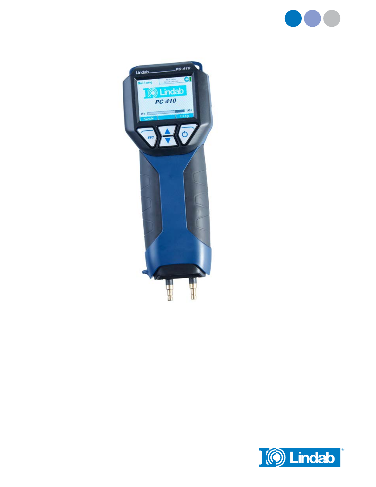
PC 410
Manual Flow and Pressure Meter

2
Content
1 General Information 3
1.1 Operation Manual Information 3
1.2 Notes 3
1.3 Intended Use 3
1.4 Basic equipment 4
1.5 Transport 4
1.6 Information on disposal 4
1.7 Direction 4
2 Specifications 5
2.1 Measured values 5
2.2 Calculated Values 6
2.3 Logger 6
2.4 Technical Data 7
3 Component explanation 8
3.1 Basic unit 8
3.2 Probes and Components 10
3.3 Function 12
3.4 Operating Mode 13
3.5 Display and key setup 13
4 Getting started 15
4.1 Check battery status 15
5 Operation 17
5.1 Turning the Meter on and Self Check 17
5.2 Measuring 17
5.3 Using the Pressure computer 18
6 Measurement modes 20
6.1 Selecting the main menu 20
6.2 Option “Air flow (k value)” 21
6.2.1 Theoretical background 21
6.2.2 Connecting the meter to the vent 23
6.2.3 Performing the Test 24
6.3 Option “K-Value Matching” 26
6.4 Option “Airflow (Pitot)” 28
6.4.1 Measuring the airflow (Pitot) 28
6.4.2 Grid-point measurements 29
6.5 Option “Air speed” 32
6.5.1 Measuring the air speed 32
6.5.2 Theoretical background 32
6.6 Option “4 PA Test” 34
6.7 Option “Heating Check” (Energy
Utilization Check) 37
6.8 Option „Volume“ 42
6.9 Option “U-value” 45
6.10 Option “Graph / Record” 46
6.11 Option „Print“ 48
6.12 Option "Setup" 47
6.13 Option "Save measurements" 49
7 Option 'Data management' 50
7.1.1 Save Customer Records 50
7.1.2 Creating a New Customer Folder 51
7.2 Option "Data management" 51
7.3 Data Transfer with the Computer or
Notebook 52
7.4 Data Logging 52
8 Troubleshooting 52
9 Maintenance 53
9.1 Maintenance work 53
10 Warranty and Service 53
10.1 Warranty 53
11 Accessories 54
12 Declaration of conformity 55

3
1. General information
1.1 Operation Manual Information This operation manual allows you to safely work with the PC
410. Please keep this manual for your information.
The PC 410 Flow and Pressure Meter should be employed by
professionals for its in-tended use only.
Liability is void for any damages caused by not following this
manual.
1.2 Notes
WARNING!
Not following this warning can cause injury or death.
ATTENTION!
Not following this note can cause permanent damage to
the device.
NOTE!
Useful information
1.3 Intended Use The meter can be used for the measurement of differential
pressure, airflow, flow speed and temperature as well as for
the registration of humidity and ambient pressure. It is especi-
ally designed for the following purposes:
• Acceptance measurements at ventilation systems accord-
ing to DIN EN 12599.
• 4 PA Pressure Test to confirm the combustion air availabil-
ity.
• Measurement of the ventilation loss and the surface loss.
• Flow pressure, installation pressure, standing pressure, jet
pressure.
• Flow measurement in air and flue gas ducts.
• Data logger.
4
1.4 Basic equipment
Device Components
PC 410 Flow and Pressure Meter with bat-
teries
Hand strap
Silicone hose, 6 m
Rubber hose, 1,5 m
Plastic case
1.2 Transport
ATTENTION!
Improper transport can harm the instrument.
Always transport the instrument in the provided carrying case
in order to prevent damage. The pressure connectors have to
be protected by the protection cap.
The case is included in the sets and also can be bought
separately.
1.6 Information on disposal Electronic equipment does not belong into domestic waste,
but must be disposed in accordance with the applicable
statutory provisions.
You may hand in any defective batteries taken out of the unit
to our company as well as to recycling places of public dis-
posal systems or to selling points of new batteries or storage
batteries.
1.7 Contact Please contact your local Lindab distributor
or send for technical questions an E-Mail:

5
2. Specifications
2.1 Measured values Description Data
Range ±100 hPa
Accuracy < 3 % of the reading, if the value is
< ± 10 Pa, better than ± 0.3 Pa
Resolution 0.1 Pa at -1100 hPa to +1100 hPa,
otherwise 1 Pa
Measurement of very small
pressures Description Data
Range ±100 hPa
Accuracy < 3 % of the reading, if the value is
< ± 10 Pa, better than ± 0.3 Pa
Resolution ± 0,01 Pa
Internal temperature
measurement Description Data
Range -20 °C to 60°C
Accuracy < ± 1 °C
Resolution 0.1°C
External temperature
measurement
(optional, e.g. with
Measuring Pliers for
Temperature Measurement
or Special Wall Temperature
Probe)
Description Data
Range 2 canals, -20.0 °C to +800.0 °C
Accuracy < ± 2 °C at 0°C to 133°C, otherwise
1.5 % of the value, according to the
directive EN 50379-2
Resolution 0.1°C
Humidity measurement
(only AF version)
(integrated humidity sensor)
Description Data
Range 0 % to 100 % RH (relative
humidity), non condensing
Accuracy < ± 2 % RH, in range 0 to 90 % RH,
otherwise < 3 % RH
Resolution 0.1 % RH
Ambient Pressure measure-
ment (only AF version with
humidity sensor)
Description Data
Range ±300 hPa, else 1100 Pa
Accuracy < ± 1.5 % hPa of reading
Resolution 0.1 hPa
6
2.2 Calculated values Variable Calculation
Pressure units hPa, Pa, mmH2O, PSI, inwc, bar,
mbar,
conversion according to the general
conversion rules.
Temperature units °C, °F,
conversion according to the general
conversion rules.
Air speed Description Data
Range 0.3 m/s to 120 m/s
Resolution 0.01 m/s
Continuous density
correction
automatic, with temperature signal.
2.3 Logger Description Data
Extent 9999 measurements, each with the
measured value of pressure and
humidity (optional) and three tem-
perature values (if the external tem-
perature sensors are connected) can
be stored in the internal memory.
The user can set the log rate from 1
second to 24 hours.
USB interface for
data transfer to a
PC
Permanent online data, already
during the registration.
User adjustable log
rate
Sampling interval of 1 second to 24
hour can be set.
NOTE!
Ensure that the meter is connected to the power supply or
that the batteries are charged.

7
2.4 Technical Data Description Data
Power
Consumption
4 AA rechargeable batteries or 4 AA
disposable batteries 1.5 volt
- working mode: ca. 60 mA,
- off-mode and log mode:
ca. 45 µA for clock and processor
Interface USB- (COM-Port),
data transfer to the PC.
It is possible to transfer the data
directly from the meter to the TD 600
thermal fast printer.
Storage
temperature
-20 °C to +60 °C
Operating
temperature
5 °C to +40 °C
Mass ca. 365 g, with batteries and
integrated magnet
Dimension 80 × 550 × 60 mm
Date and time Date and time are included in the
measurement report
Internal Memory 2 MB

8
11
12
2
9
10
1
8
45
6
7
3
3. Component explanation
3.1 Basic unit
Fig. 1: Overview

9
Number Part
1 Mini-USB-Port
2 Connection for protection cap
3 Power jack
4 Color display
5ESC key context-sensitive
Escape
NOTE!
Keeping this key depressed will always call up the main menu.
6 Arrow keys The function changes according to the context.
Scroll up and down.
7 ENTER
and On-/Off key
a) Confirm the setting.
b) The function of the key changes according to the context.
c) Press and hold the key for 3 seconds to turn off the unit.
8 Infrared interface Thermal fast printer to print out the measurement report
9 Overpressure socket (+) Main connection
10 Underpressure socket (--) Reference socket for the measurement of the differential
pressure and static socket for the S-tube probe
11, 12
14
Standard jacks for temperature probes NiCr-Ni
14 Battery cover (in Fig. 1 on the rear side)
There are diffusion openings for the internal registration of the
humidity and temperature on the rear side of the Lindab
PC 410. The internal temperature measurement is necessary
for the temperature compensation of the pressure sensor.
10
3.2 Probes and Components
S-tube probe for measuring the flow speed (see chapter 6.5)
and the airflow (see chapter 6.2).
• Insert the plug of the S-tube probe into jack 11 (Fig. 1) of
the PC 410.
• Connect the overpressure hose (turned against the flow) of
the S-tube probe to the overpressure socket (+) (Fig. 1, part
9) and the underpressure hose to the underpressure socket
(-) (fig. 1, part 10).
Fig. 2: S-tube probe
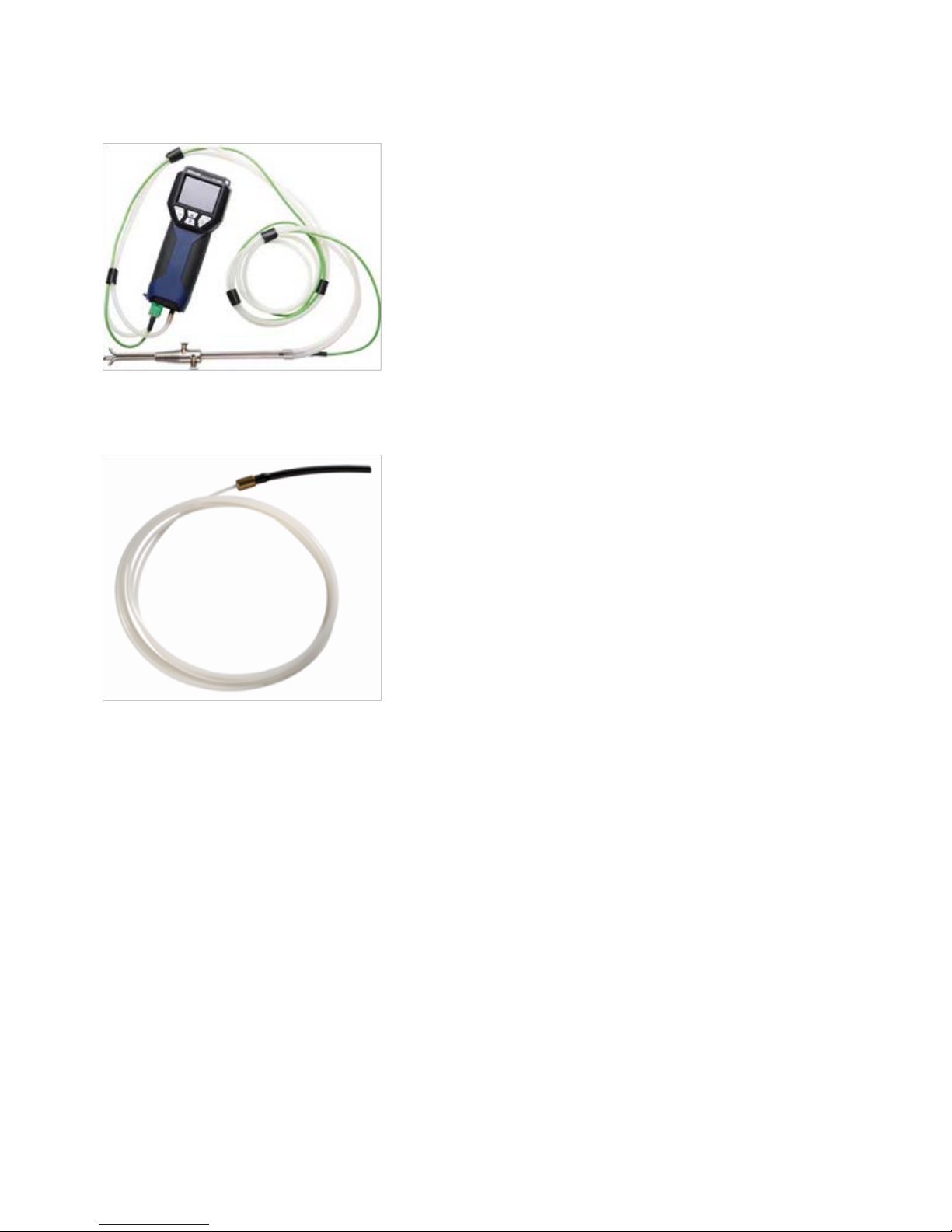
Flexible capillary
For the 4 PA test two flexible capillaries are needed.
Fig. 3: Capillary tube
Table of contents
Popular Multimeter manuals by other brands


Gossen MetraWatt
Gossen MetraWatt METRAmax 6 operating instructions

PeakTech
PeakTech 4000 Procedure of calibration

YOKOGAWA
YOKOGAWA 90050B user manual

Gossen MetraWatt
Gossen MetraWatt METRALINE DMM16 operating instructions

Fluke
Fluke 8846A Programmer's manual

Tempo Communications
Tempo Communications MM200 instruction manual


