DER EE DE-5003 User manual

- 0 -
User Manual
Digital Multimeter+LCR
Model︰DE-5003/5004
Thank you for purchasing our products. Please read this instruction
manual before using the meter and keep it properly for contingent use.
7F, No.351, Sec. 2, Chung Shan Rd.,
Chung Ho Dist., New Taipei City 23504, Taiwan
TEL: (02)2226-6789(REP.) FAX: (02)2226-7979
E-mail:deree@deree.com
http://www.deree.com.tw
V0.3

- 31 -

- 1 -
User Manual ……Table of Contents
(1) Parts Identification...........................................................05 ~ 06
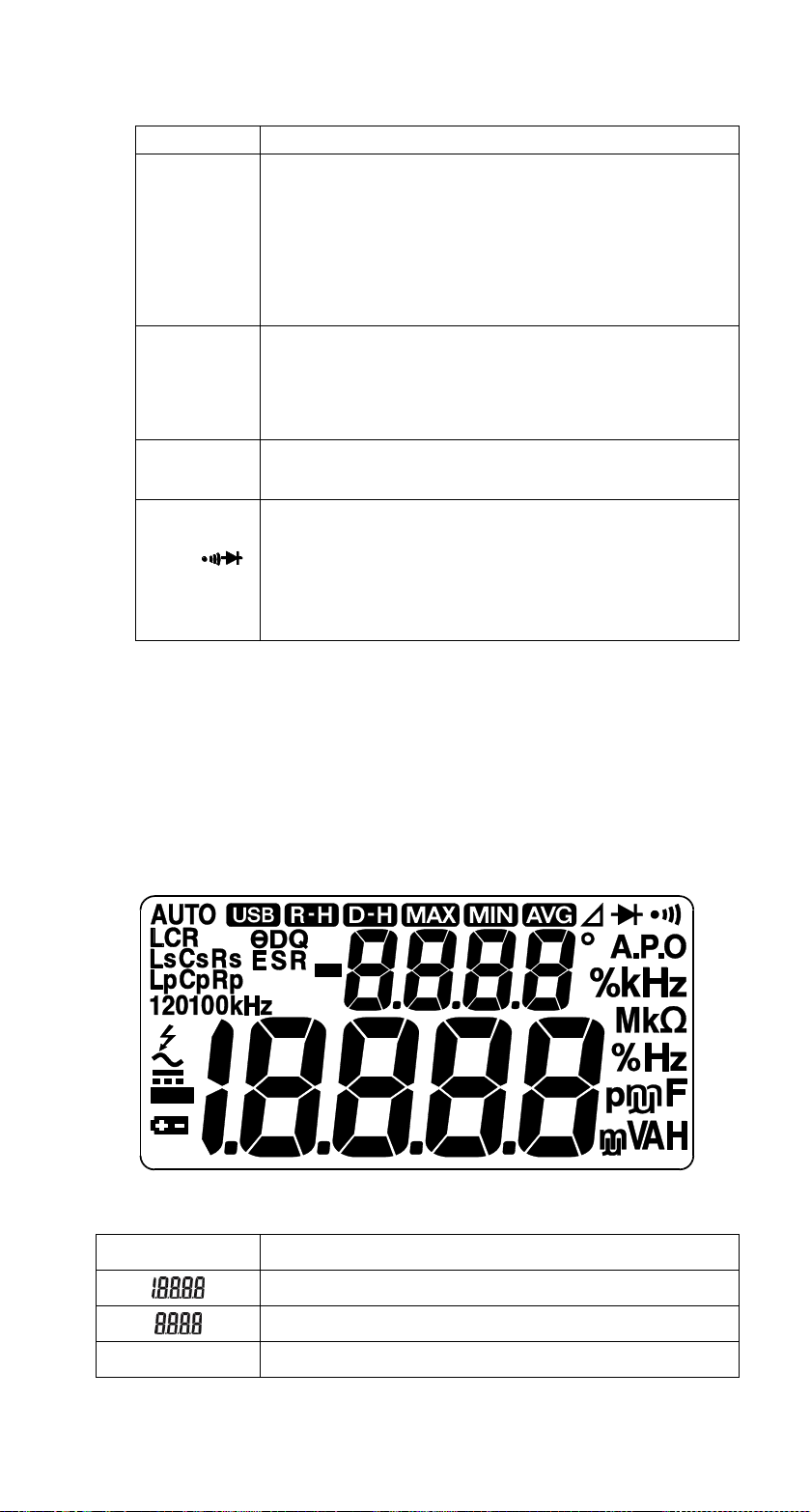
(2) Display ..............................................................................06 ~ 07
(3) Function Switch..........................................................................08
(4) Buttons Operations............................................................09 ~ 13
■SELECT ...............................................................................09
■RANGE ................................................................................09
■REL ............................................................................09 ~ 10
■HOLD...................................................................................10
■Backlit ( ).........................................................................10
■MAX/MIN.....................................................................10 ~ 11
■Integrate REL + HOLD.........................................................11
■Integrate REL + MAX/MIN...................................................11
■Integrate MAX/MIN + HOLD................................................12
■Integrate REL+MAX/MIN+HOLD................................12 ~ 13
■θDQ......................................................................................13
■Buttons vs Measuring Functions.........................................14
(5) Measurement Functions.....................................................15 ~ 23
■Measuring AC Voltage ( )................................................15
■Measuring DC Voltage ( )................................................16
■Measuring DC / AC Millivoltage (mV) ............................17
■Measuring Resistance ( Ω )..................................................18
■Continuity Check ( )........................................................19
■Diode Test( )...................................................................20
■Frequency (Hz) + Duty (%) Measurements..........................21
■LCR Measurement................................................................22
■DC & AC Current Measurement (μA、mA、A)...............23
(6) Auto Power Off Function.............................................................24
(7) Replacing Fuses................................................................24 ~ 25
(8) Replacing Battery.......................................................................25
(9) Specifications.....................................................................26 ~ 29

- 2 -
For safety, read the users manual carefully and keep it
with the meter together for further reference.
Precautions:
To avoid possible electrical shock or personal injury, please pay
extra attention on those symbols indicated on the manual and
corresponding illustration.
Warning:Improper or careless may result in
personal injury or even death.
Caution:Improper or careless may result in
damage to the meter or other
equipment
Dual Insulation
AC- Alternating Current
DC- Direct Current
Grounding –Earth Terminal
Fuse
Warning
⚫Set the function switch and function key at the
proper position and function before measuring.
⚫Remove test leads from the circuit being tested
before switching functions.
⚫Do not apply more than the rated range of function
specified.
⚫Check and make sure the meter or test leads are
intact before use. Do not use the meter or test
leads if they appear damaged.
⚫When using the test leads, always keep hands
behind the guard ring.

- 3 -
⚫When measuring resistance, first switch off the
power to the circuit under test, and verify that the
voltage is zero.
⚫Keep the meter dry. Do not use it with wet hands
or if there is moisture in or on the meter.
Warning
Maximum input voltage according to overvoltage
installation category of safety standard.
Measuring Category
Maximum input
voltage
CAT. II
1000V
CAT. III
600V
Caution
⚫Do not use the meter near equipment emitting noise
or in environments with sudden temperature
changes. Unstable or inaccurate reading may occur.
⚫When finished measurement, turn the function
switch back to OFF position to turn off the meter
completely. There is minor power exhaustion if the
meter is power off by auto-power-off function.
⚫If it is necessary to clean the meter, use a soft cloth.
Never use solvents.
⚫Do not expose the meter to direct sunlight, extreme
temperatures or moisture.
⚫Do not attempt to open the case except the battery
door for replacing battery or fuses.
⚫Any impact or drop of battery will result leakage
afterwards and possibly damage the meter. Thus,
don’t use those batteries if occurred.
⚫Take the battery out of the meter if it will not be used
for several weeks or storage.
⚫When symbol displays, replace the battery
immediately.

- 4 -
Overvoltage Installation Category:
Maximum input voltage of the meter is according to overvoltage
installation category of safety standard. Do not apply more
than the rating voltage.
Measuring
Category
Description
Example
CAT. II
Measurements in electrical circuits
which are directly connected to the
low-voltage mains via plug
in household, office and
laboratory applications
CAT. III
Measurements in building installations
stationary consumers,
distributor terminals, devices
connected permanently to the
distributor
CAT. IV
Measurements at power sources for
low-voltage installations
Meters, mains terminals,
primary over current protection
device
•Warning
Radiation immunity affects the accuracy of meter under the conditions
specified in IEC61326-1 Also may result the meter malfunctions
where has equipments emitted strong electromagnetic interference.
Entrance cable
In-house mains power
power
distributor
Equipment
wall
socket
stationary
equipments
…etc

- 5 -
(1) Parts Identification
①Trademark & model
②Liquid crystal display ( LCD )
Display measuring symbols, units and readings
Refer to functions at page 6~7
③Buttons
Refer to functions at page 9~13
④Function switch
Refer to functions at page 8
⑤Range label
Indication of functions and terminals
drawing:DE-5004

- 6 -
⑥Input terminals
Terminal
Description
A
(for red test lead)
Positive input terminal for AC or DC
current measurement to 10A.
*11~20A overload for 30 seconds maximum.
**Pause 10 minutes at least before next
measurement.
μA mA
(for red test lead)
Positive input terminal for AC microampere /
milliampere or DC microampere /
milliampere measurement.
COM
(for black test lead)
Input terminal for all measurements.
V Ω
LCR
(for red test lead)
Positive input terminal for voltage,
resistance, diode, continuity, frequency, duty
& LCR (inductance / capacitance /
Resitance) measurements.
⑦Battery door
⑧Stand rack
⑨Test leads (red & black)
⑩Sheath
(2) Symbol on Display
Symbol
Description
Primary reading
Secondary reading
A.P.O
Auto power off

- 7 -
AC measurement mode
DC measurement mode
Negative polarity
Replace battery (low power indication)
Relative mode
AUTO
Auto range
Range hold
Data hold
Maximum value
Minimum value
Continuity
Diode
Input high Voltage alert
Hz , kHz ,
MHz
Units of frequency –Megahertz, Kilohertz
and Hertz
%
Unit of Duty
Ω, kΩ, MΩ
Units of resistance –Megaohms, Kiloohms
and Ohms
mV, V
Units of voltage - millivoltage & voltage
μA, mA, A
Units of current - microampere, milliampere
and ampere
LCR
L/C/R measurement mode
Ls Lp
Inductance in series
or parallel mode is active
Cs Cp
Capacitance in series
or parallel mode is active
Rs Rp
Resistance in series
or parallel mode is active
100Hz, 1kHz,
10kHz
Test frequency indication
pF, μF, mF
Units of capacitance –picofarad,
nanofarad, microfarad , millifarad and farad
μH, mH
Units of Inductance –
microhenry, millihenry and henry
°
Unit of phase angle
θDQ
Dissipation, Quality factor or Phase angle is
active for L & C measurement mode

- 8 -
(3) Rotary Switch Positions
Positions
Description
OFF
Power off
AC voltage measurement
DC voltage measurement
mV
DC/AC millivoltage measurement
Ω
Resistance/ Continuity/ Diode measurement
--initial function is Resistance.
Hz %
Frequency / Duty measurement
LCR
Inductance/ Capacitance/ Resistance
Measurement.
-- initial function is Inductance
μA
DC/AC microampere measurement
--initial function is DC uA.
mA
DC/AC milliampere measurement
-- initial function is DC mA.
A
DC/AC ampere measurement
--initial function is DCA.

- 9 -
(4) Button Operations
■SELECT
Press SELECT button to shift the functions as below:
Rotarysw. position
Function Shift
mV
DC/ AC mode
Ω
Resistance / Continuity / Diode
LCR
Inductance / Capacitance / Inductance
μA
DC/ AC microampere
mA
DC/ AC milliampere
A
DC/ AC ampere
■RANGE
⚫Press RANGE button to enter manual range, symbol
displays and AUTO range indicator turns off. In manual
range mode, press RANGE button to choose the proper
range for measurement as list.
⚫Shift ranges as below table:
RotarySW.
position
Press RANGE button
to shift ranges
Initial
range
6.000V / 60.00V / 600.0V / 1000V
6.000V
6.000V / 60.00V / 600.0V / 1000V
6.000V
Ω
600.0Ω / 6.000kΩ / 60.00kΩ /
600.0kΩ / 6.000MΩ / 60.00 MΩ
60.00 MΩ
Hz%
600.0Hz / 6.000kHz / 60.00kHz /
600.0kHz / 6.000MHz / 20.00MHz
600.0Hz
μA
600.0μA / 6000μA
DC 600.0μA
mA
60.00mA / 600.0mA
DC 60.00mA
⚫Hold RANGE button ≧2 sec. will retrieve auto range
function, indicator turns off and AUTO symbol
displays.
■REL ( REL )
⚫Press REL button during the measurement, symbol
displays and the Relative function turns on.
⚫In REL mode ,the manual range turns on
automatically and cancel auto-range feature.

- 10 -
⚫The range is locked according to the first input value. To
prevent over range during measurement, use RANGE
key to choose proper range before entering Relative
mode.
⚫The difference (relative value) between 2 input signals
displays on LCD.
[For example:]
◼The first input is X, press REL key will store X as the
reference value and display 0 on LCD.
◼The 2nd input is Y will display Y minus X on LCD.
◼The 3rd input is Z, will display Z minus X on LCD.
And follow the same rule of the above for the next inputs.
⚫To cancel the Relative function, press REL button again.
The indicator turns off and resumes the normal
measuring mode.
⚫REL button also performs calibration process for LCR
measurement.
■HOLD
⚫Press HOLD button to retain data during measuring.
symbol displays and freeze the reading .
⚫Press HOLD again to resume normal measuring mode.
⚫In Hold mode, either REL or MAX/MIN button is disabled.
■Backlit ( )
⚫Press “ ” button to turn on the backlight of LCD.
⚫Press “ ”button again to turn off the backlight.
⚫Or the backlight will turn off automatically in around 60
seconds after activation.
■MAX/MIN
⚫Press MAX/MIN button, and symbols turn on
and the maximum value displays on the sub display. And
current value on the main display. In MAX/MIN mode the
manual range (R-H) turns on automatically and cancel
auto-range (AUTO) and A.P.O features.
⚫Press MAX/MIN button again will shift to the minimum
value on the sub display. symbol turns on and
symbol is off.
⚫In MAX/MIN mode, the maximum or minimum value on
the sub display will update according to the changes of
measuring value on the main display.

- 11 -
⚫Hold MAX/MIN button for ≧2 sec will cancel the function
and back to normal measuring mode.
⚫In MAX/MIN mode, REL button is disabled.
■Integrate REL + HOLD
⚫Press REL button during measurement to enter Relative
mode. & display. The reference value is stored
and display on sub-display and the relative value on main
display and renews according to the inputs.
⚫Press HOLD button to enter REL+HOLD mode,
symbol is on to freeze the measuring value and mode on
display. In Hold mode, either REL or MAX/MIN button is
disabled.
In normal
operation
Press”
REL”
Press”
REL”
Relative Value
Press”
HOLD”
Press”
HOLD”
Retain Relative
Value
■Integrate REL + MAX/MIN
⚫Press REL button during measurement to enter Relative
mode. & display. The reference value is stored
and display on sub-display and the relative value on main
display and renews according to later inputs.
⚫Press MAX/MIN button to enter REL+Max/Min mode,
A.P.O is off. Maximum-Relative ( & ) and
Minimum-Relative ( & )and the reference values
(, & blinking) display on sub-display and
press MAX/MIN button to shift the reading. The update
Relative value displays on main display always.
⚫REL button is disabled in REL+MAX/MIN mode.
⚫To cancel REL+MAX/MIN mode, hold MAX/MIN button
≧2 sec. first until MAX/MIN symbol is off and then press
REL button to resume normal measuring mode.

- 12 -
■Integrate MAX/MIN + HOLD
⚫Press MAX/MIN button to enter MAX/MIN value recording
mode. (*refer to MAX/MIN operation for details)
⚫Press HOLD button to enter MAX/MIN+HOLD mode to
freeze the measuring value and mode on display.
⚫Press MAX/MIN button to shift reading the maximum and
minimum values be retained.
■Integrate REL+ MAX/MIN + HOLD
⚫In REL+MAX/MIN mode, press HOLD button to enter
REL+MAX/MIN+HOLD mode to freeze the values and
mode.
⚫Press MAX/MIN button to shift reading
Maximum-Relative ( & ) and Minimum-Relative
( & ) and the reference values ( , &
blinking) display on sub-display. REL button is
disabled in REL+MAX/MIN+HOLD mode.
In normal
operation
Display MIN valueDisplay MAX value
Retain MIN value
"D-H" "R-H" "MIN"
Retain MAX value
"D-H" "R-H" "MAX"
Press MAX/MIN
Hold MAX/MIN
≧2sec.
Hold MAX/MIN ≧2sec.
Press HOLD Press HOLD
Press
MAX/MIN
Press
MAX/MIN

- 13 -
⚫To cancel this mode, first press HOLD button to relief
from HOLD mode ( is off) and then hold MAX/MIN
button ≧2 sec. to out of MAX/MIN recording mode (
& is off) and last to press REL button ( is off) to
resume normal measuring mode.。
■θDQ
⚫θDQ button is only available in LCR measurement.
⚫Press θDQ button to select the parameter at the sub
display.
Shift function lists
Parameter on sub-display
In C (Capacitance) test mode
D →θ(in cycle)
In L (Inductance) test mode
Q →θ(in cycle)
In normal
operation
Display Min. Relative
value
Display Relative
value
Display Max. Relative
value Display Relative value
[MAX & MIN symbols
blink]
Retain Min. Relative
value
Retain Max. Relative
value Retain Relative value
[MAX, MIN, D-H symbols
blink]
Press REL Press REL
Press MAX/MIN
Hold MAX/MIN ≧2 sec
Hold MAX/MIN ≧2 sec
Hold MAX/MIN ≧2 sec
Press MAX/MIN
Press HOLD Press HOLD Press HOLD
Press MAX/MIN
Press MAX/MIN Press MAX/MIN

- 14 -
■The following table lists the available button function
versus every measurement mode.
Button
function
SELECT
RANGE
HOLD
MAX
MIN
REL
(CAL)
θDQ
─
●
●
●
●
●
─
─
●
●
●
●
●
─
mV
●
─
●
●
●
●
─
Ω
●
●
●
●
●
●
─
●
─
●
●
●
●
─
●
─
●
●
●
●
─
Hz+ Duty
─
●
●
●
─
●
─
LCR
●
─
●
─
●
●
●
●
●
●
●
●
●
─
●
●
●
●
●
●
─
●
●
●
●
●
●
─
●
●
●
●
●
●
─
●
─
●
●
●
●
─
●
─
●
●
●
●
─
Note: ●: available ─:unavailable

- 15 -
■Measurement Functions
AC Voltage Measurement ( )
Caution
To prevent possible personal injury or damage the meter, do
not apply the circuits exceed 1000V.
Range: 0.000V~1000V
(4 ranges : auto range and manual range mode for option )
1. Set rotary switch to position.
2. Plug black test lead into the COM terminal and red test
lead into the V terminal.
3. Connect test leads to the circuit to be tested. Allow time
for the value to stabilize and then read the AC voltage
measurement on the LCD.
4. When input exceeds 1010V, “OL”& high voltage alert
symbol display and buzzer is on to alarm a high voltage
presents.
5. The corresponding frequency of the AC voltage value
syncs displaying on sub-display. It may not display
properly if the input AC voltage is too small to be
detected.
6. When finished, turn rotary switch to OFF position to turn
off the meter.

- 16 -
■DC Voltage Measurement ( )
Caution
To prevent possible personal injury or damage the meter, do
not apply the circuits exceed 1000V.
Range: 0.001V~1000V
(4 ranges: auto range & manual range mode for option)
1. Set rotary switch to position.
2. Plug black test lead into the COM terminal and red test
lead into the V terminal.
3. Connect test leads to the circuit to be tested. Allow time
for the value to stabilize and then read the DC voltage
measurement on the LCD.
4. When input exceeds 1010V, “OL”& high voltage alert
symbol display and buzzer is on to alarm a high voltage
presents.
5. When finished, turn rotary switch to OFF position to turn
off the meter.
(-) black test lead
(+) red test lead

- 17 -
■DC/AC millivoltage Measurement ( mV )
Caution
To prevent possible personal injury or damage the meter, do
not apply the circuits exceed 1000V.
Range: 600.0mV
1. Set rotary switch to mV position.
2. Plug black test lead into the COM terminal and red test
lead into the V terminal.
3. Press SELECT button to choose ACmV( ) or
DCmV( ) for measurement.
4. Apply test leads to the circuit to be tested. Allow time
for the value to stabilize and then read the voltage
measurement on the LCD.
5. The corresponding frequency of the AC voltage value
syncs displaying on sub-display. It may not display
properly if the input AC voltage is too small to be
detected.
6. When exceed 600mV, “OL”displays on LCD.
7. When finished, turn rotary switch to OFF position to
turn off the meter.
* For DC measurement, connect to correct polarity is
necessary.
(-) black test lead
(+) red test lead

- 18 -
■Resistance Measurement ( Ω )
Warning
To prevent damaging the meter, must switch off the power
of the circuit to be tested before conducting the
measurement.
Range: 600.0Ω~60.00MΩ
(6 ranges: auto range & manual range mode for option)
1. Set rotary switch to “Ω ”position. and OL with MΩ
unit display on LCD.
2. Plug black test lead into the COM terminal and red test
lead into the Ωterminal.
3. Connect test leads to the object to be tested. Allow time
for the value to stabilize and then read the resistance
measurement on the LCD.
4. Polarity is not in consideration when measuring
resistance.
5. When finished, turn rotary switch to OFF position to turn
off the meter.
Note: During measuring, do not touch the probes of test
leads with bare hands to prevent affecting the accuracy.
(-) black test lead
(+) red test lead
This manual suits for next models
1
Table of contents
Popular Multimeter manuals by other brands

Extech Instruments
Extech Instruments 380224 instruction manual

Elenco Electronics
Elenco Electronics M-2666K Assembly and instruction manual

KPS
KPS KPS-MT420 instruction manual

HoldPeak
HoldPeak 39B Operator's manual

Wavetek
Wavetek Meterman CR 50 Operator's manual

Klein Tools
Klein Tools ET200 instruction manual