Lindsay Broadband DOCSIS LBDG-S90 User manual

Printed 11/12/2020 1 of 12 Rev. 1
INSTALLATION MANUAL
5-1930
PoE++ DOCSIS®Gateway LBDG-S90

Printed 11/12/2020 2 of 12 Rev. 1
LBDG-S90
IMPORTANT SAFETY AND INSTALLATION WARNINGS
WARNING: DO NOT ATTEMPT TO SERVICE THIS PRODUCT YOURSELF AS
OPENING OR REMOVING COVERS MAY EXPOSE YOU TO DANGEROUS
VOLTAGES OR OTHER HAZARDS. REFER ALL SERVICING TO QUALIFIED
SERVICE PERSONNEL.
MOUNTING:
Mount this product only as described in the installation instructions, otherwise
it may fall causing serious personal injury and/or damage the unit. Use only
with the brackets supplied with the product. Do not use attachments not
recommended for this product as they may cause hazards.
SERVICING:
Remove power from this device and refer servicing to qualified personnel
under the following conditions:
1. If the inside of the station has been exposed to rain or water.
2. If the station does not operate normally by following the operating
instructions. Adjust only those controls that are covered by the
operating instructions as an improper adjustment of the controls may
result in damage and will often require extensive work by a qualified
technician to restore the unit to its normal operation.
3. If the unit has been dropped or the chassis has been damaged.
4. If the unit exhibits a distinct change in performance.
REPLACEMENT PARTS:
When replacement parts are required, be sure the service technician has used
replacement parts specified by the manufacturer or have the same
characteristics as the original part. Unauthorized substitutions may result in
fire, electric shock or other hazards.
SERVICE DEPOT:
Lindsay Broadband Inc.
2-2035 Fisher Dr.
Peterborough, ON K9J 6X6
Canada
+1.705.742.1350
Printed 11/12/2020 3 of 12 Rev. 1
LBDG-S90
SECTION 1 PRODUCT DESCRIPTION
1.1 Introduction
This manual is written to help service personnel understand and install the
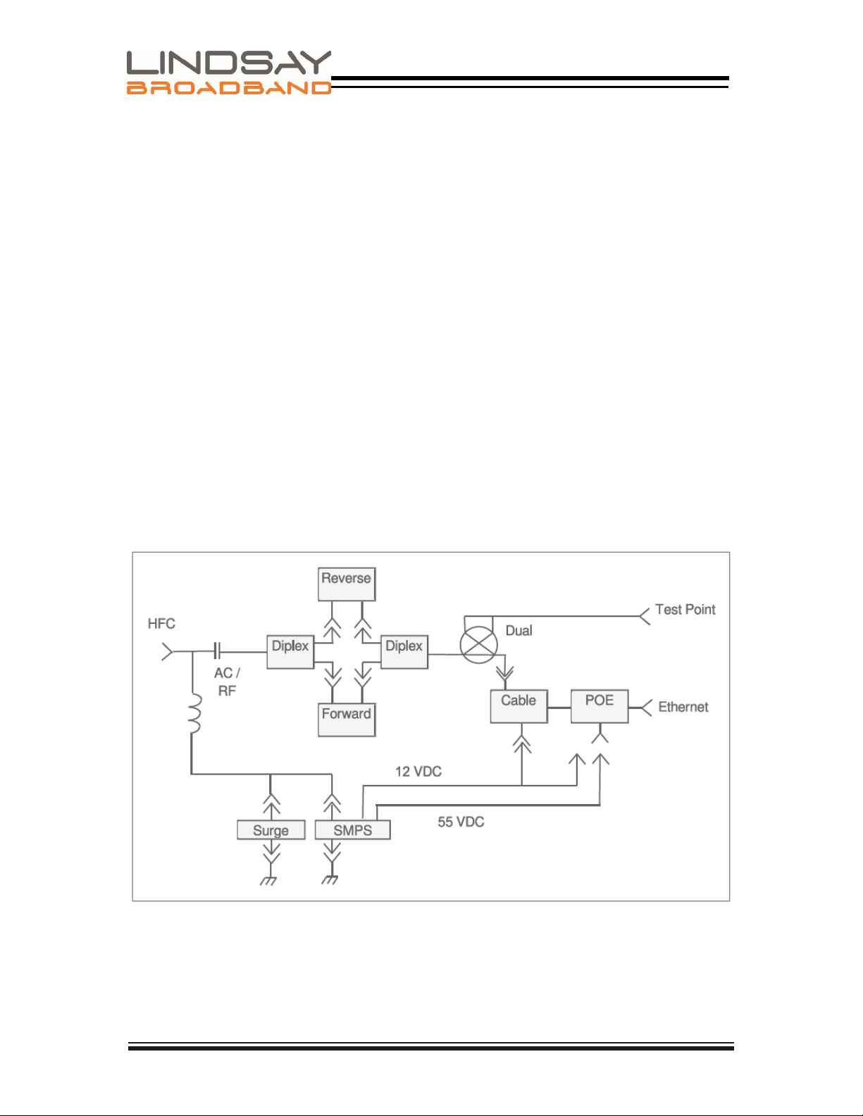
Lindsay DOCSIS Gateway LBDG-S90. This first section gives a full product
description and a block diagram. The remaining sections provide component
identification diagrams, installation instructions, and specifications.
1.2 General Description
This Gateway uses the HFC network to power and backhaul IP based, 48 Volts
DC powered devices. The Gateway can provide up to 90W by using four pairs
of AWG22 black and red wires. It can be connected to the HFC network
through any power -passing tap or coupler. The cable modem is configured,
as usual, by your DOCSIS provisioning software.
The modem within this Gateway, in conjunction with the standard CableLabs®
SNMP MIB, can also be used to monitor plant conditions.

Printed 11/12/2020 4 of 12 Rev. 1
LBDG-S90
1.3 Housing
A rugged die cast aluminum housing of clamshell design is used. Externally, the housing
base has installation mounts and three connectors:
• A type F test point connector. Signal levels read at this connector are -20 dB relative to
the cable modem F port.
• A 5/8-24 threaded hole for KS type connect ion to the HFC network.
• A 5/8-24 threaded hole for RJ45 and power wires access to the unit.
Dual gaskets provide RFI isolation and an airtight seal to 15psi. The housing can be strand
mounted. An optional hardware kit for wall, mast or pedestal mounting is available. The
station size is approximately 254 x 432 x 165 mm (10 x 17 x 6.5 in.). Its weight is around
7.6 Kg (16.8 lbs).
1.4 Major Components
Internally, the housing bottom harbors the HFC interface board and POE power injector.
The power supply and cable modem are housed in the lid. There are a large number of
cable modem options available. A high efficiency switch mode power supply is used.
Filtering to prevent the switching regulator noise from reaching the AC and DC lines is
provided.
The lid interconnects to the housing base with a harness of power, coax and data cables.
1.5 Interface Board
The interface circuit board, which is located in the housing base, provides the interface
to the HFC network. The following features are provided:
• An AC/RF filter is used to separate the AC power from the RF carriers.
• Sockets for the separate padding of forward and reverse DOCSIS signals.
• A Test Point provides 20dB coupling of forward and reverse power at the cable modem
port.
• Plug-in SVP type surge protection.
• Socket for optional solid state, crowbar type surge protection.
• A power-interrupt to disconnect ac power.
Printed 11/12/2020 5 of 12 Rev. 1
LBDG-S90
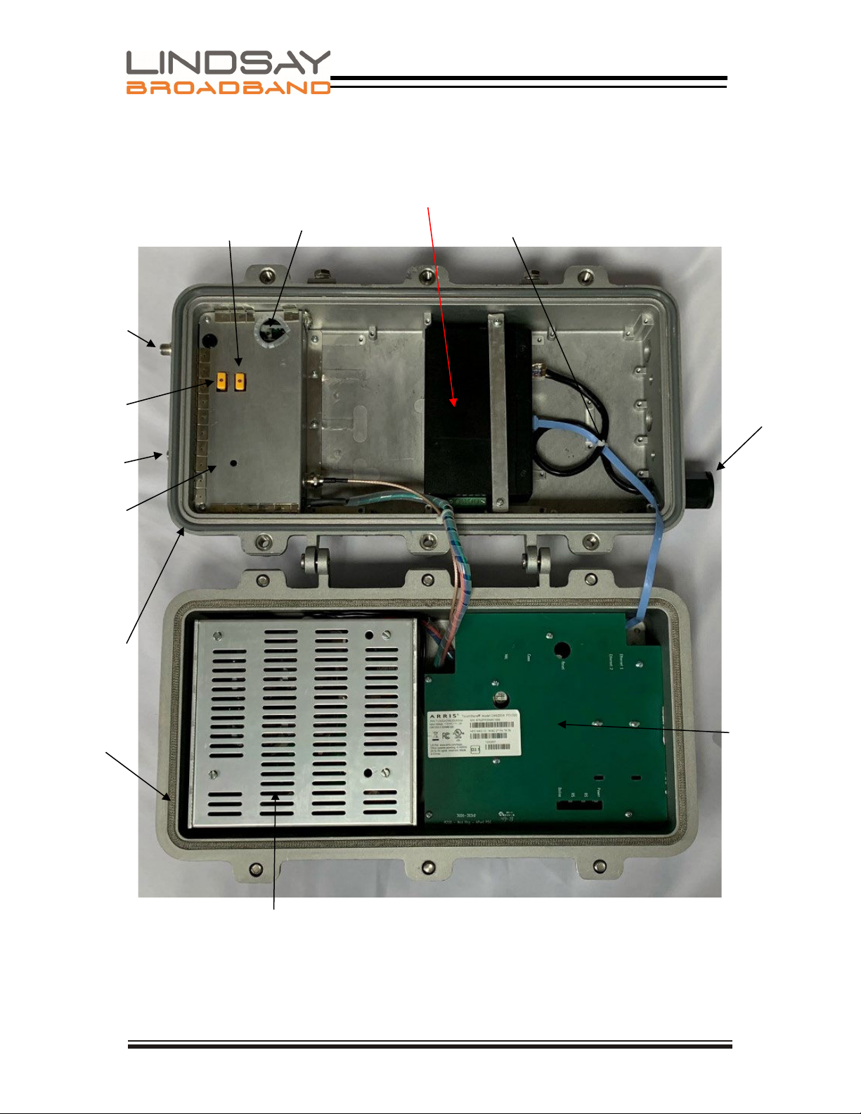
SECTION 2 COMPONENT IDENTIFICATION
Dual Rail PSU
55 Vdc/ 100 Watts
12 Vdc/ 40 Watts
EMI Seal
HFC Shielding
Cover
Weather Seal
Testpoint
Reverse Pad
HFC Input
Forward Pad
Surge Arrestor
Cable Modem
Eth Cables
RJ-45 Connector
POE Output
POE Injector

Printed 11/12/2020 6 of 12 Rev. 1
LBDG-S90
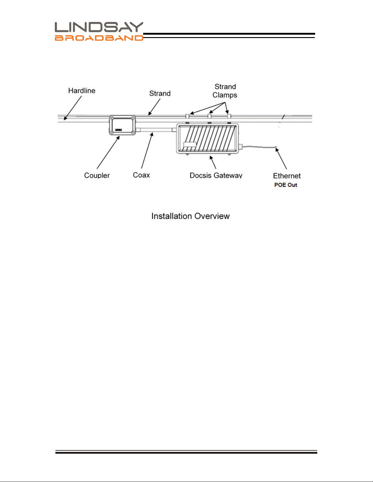
SECTION 3 INSTALLATION
Installation of the Gateway is similar to the installation of a line extender, or
any other piece of CATV equipment. The Gateway can be connected to any
power passing tap, splitter, or coupler.
3.1 Pre-Installation
Upon receipt of the Gateway, inspect the carton for any external damage. If
damage is present inspect the Gateway exterior for damage. Report any
apparent damage to the shipping agent and Lindsay Broadband sales office.
Measure the CATV system voltage at the installation site and verify that, once
it is loaded, it will be greater than the minimum input voltage spec.(40 to 90
Vrms [Quasi Square])
The output level of your splitter/tap/coupler and the value of the internal
Gateway pads should be determined ahead of time. The loss of the HFC
interface board should be allowed for when calculating these values. There is
4dB of loss in the reverse direction, and 5 dB of loss in the forward direction.
The forward pad should be selected so that power incident on the cable
modem is 0 dBmV (5 dBmV at the Gateway KS connection). For best return
path S/N, the reverse pad should be selected so that the cable modem
operates near its maximum output level.
The cable modem can be provisioned ahead of time using the MAC address
located on the label on the outside of the lid.
A 1/2” wrench is needed for both the strand clamp and housing bolts.
Printed 11/12/2020 7 of 12 Rev. 1
LBDG-S90
Printed 11/12/2020 8 of 12 Rev. 1
LBDG-S90
3.2 Installation
1. Pull the AC interrupt in the power passing tap or coupler.
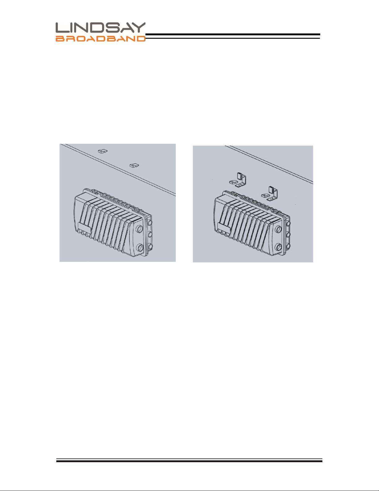
2. Using the diagrams in this section as guide, mount the gateway at its final
location. If using hanger brackets, the existing strand clamps should be left
in place to act as spacer allowing the same bolts to be used.
3. Make a coaxial connection to your HFC network at the power-passing
coupler or splitter.
4. Replace the two 0 dB RF pads with pad values that were determined before
entering the field.
5. Re-install the AC interrupt. Indicator LEDS on the cable modem will
indicate startup, discovery and provisioning. (Refer to the cable modem
installation guide for more information).
6. The forward and reverse RF levels at the cable modem can be measured
at the single test point. Readings are 20dB below the levels seen at the
cable modem F port. Make adjustments to pad values as required.
7. Without connecting a load to the Gateway verify that the Gateway output
voltage is correct. Measure at POE injector power socket (55 Vdc, Red
wire= +Vdc, Blue wire= Return)
Strand Mount
Strand Mount with
Hanger Brackets
Printed 11/12/2020 9 of 12 Rev. 1
LBDG-S90
8. Assuming your load equipment is ready to be powered, connect an outdorr
rated ethernet CAT5/6 to the load equipment Then verify that the
equipment is powered with the correct voltage.
9. (Optional) Silicone Grease can be applied to the exposed part of the O-
ring before swinging the lid back into place. This will reduce any tendency
of the O-ring to stick to the lid and ensure a weather-tight seal. To be clear,
use Silicone Grease, not Silicone Sealant, nor any other type of Grease.
10. If the EMI gasket has any frayed or loose ends tuck them back into the
channel and close the lid while ensuring that the wire harness does not
interfere with the base and lid sealing surfaces.
11.
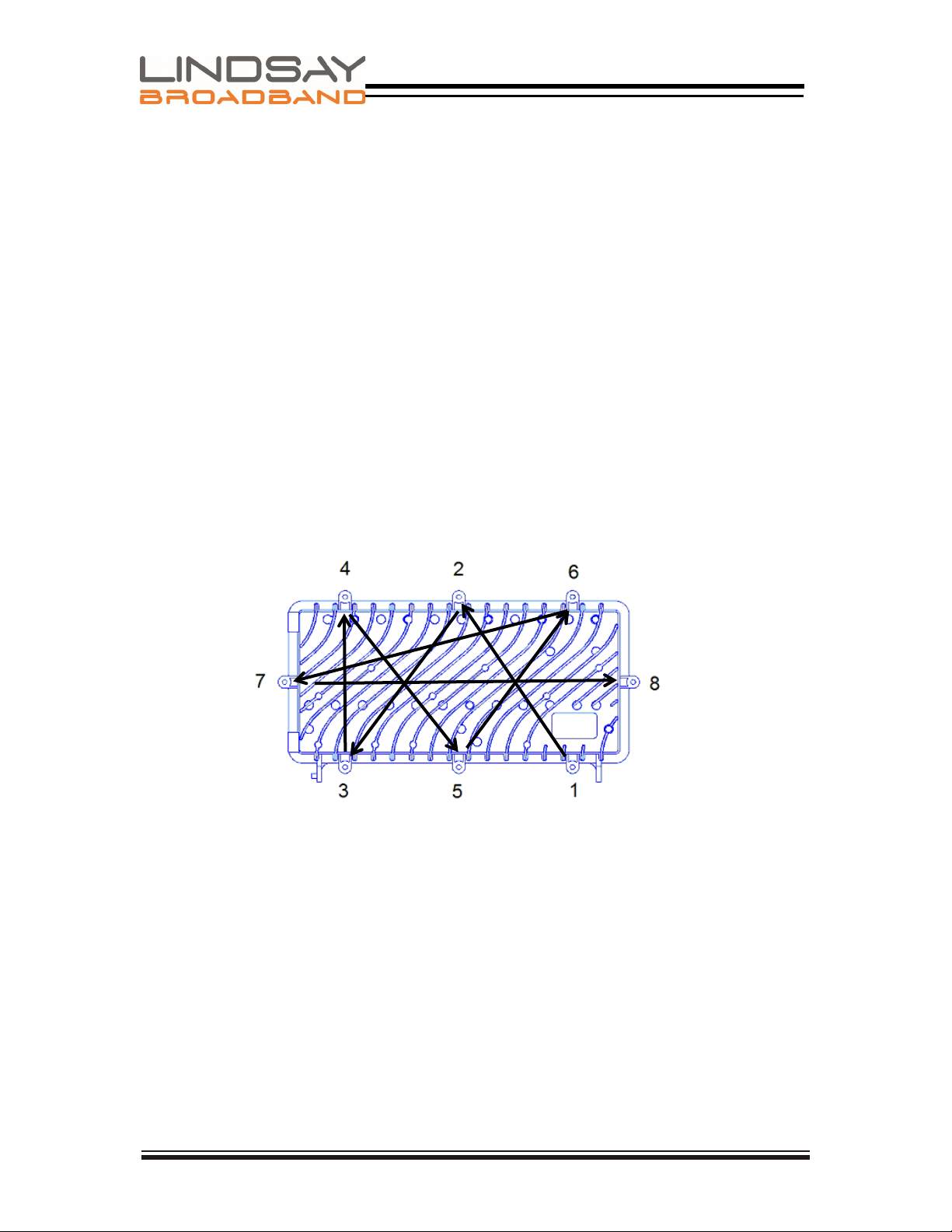
To ensure proper alignment of lid and base, finger start all lid bolts before
tightening any of them. Tighten the lid bolts, alternating diagonally to avoid
stress or warp on the housing sealing surfaces.
12.To ensure the proper functioning of the environmental gaskets, the lid bolts
should be tightened to the specified 17-ft LB or 24 Nm torque. The required
torque is easily met by using a socket wrench or, the box end of a
combination wrench, but cannot be reached using a nut driver.
13.Tape all connections to reduce moisture intake.
Lid Bolt Tightening Pattern

Printed 11/12/2020 10 of 12 Rev. 1
LBDG-S90
3.3 Power Requirements
The DOCSIS Gateway can be connected to any power passing tap, splitter, or coupler. A
DOCSIS Gateway delivering 90Watts to an IP device will draw up to 1.7 amp from a 90V
supply or 3.4 amps from a 40 V supply. You can use the following formula to calculate the
maximum current draw for your installation:

Printed 11/12/2020 11 of 12 Rev. 1
LBDG-S90
SECTION 4 SPECIFICATIONS
Parameter
Cable Modem
Band Plans
DOCSIS®3.1
Network Configuration & Management
TFTP, SNMP (V1, V2c, V3), Telnet, HTTP
Input Impedance
75 Ω
Privacy
BPI+
Downstream Modulation
Up to 32 SCQAM or 2 OFDM
RF Input Sensitivity (1)
Modem F-port
+15 to -15 dBmV
Housing 5/8" Port
+20 to -10 dBmV
Upstream Modulation
Up to 8 SCQAM or 2 OFDMA
Upstream Data Rate (Max.)
Over 1 Gbps
Transmit Power (Max.)
Modem F-port
+65 dBmV for OFDMA
+57 dBmV for 16 QAM, 4-8 upstreams
Housing 5/8" Port
+61 dBmV for OFDMA
+53 dBmV for 16 QAM, 4-8 upstreams
HFC
Return Loss
-16 dB (min.) with 75 Ω termination
-8 dB (min.) with termination by modem
Insertion Loss (1)
Downstream: -5 dB (± 1 dB)
Upstream: -4 dB (± 1 dB)
Test Point
-20 dB relative to cable modem RF-port
Pad Type
JXP, separate forward & reverse
EMI Isolation
100 dB (5-1000 MHz)
Surge Withstand (HFC)
ANSI-IEEE C62.41 Cat B3 6 kV (gas tube or solid state crowbar)
Input Powering
40-90 VAC (pseudo sine)
Ethernet
Throughput
10/100/1000 Mbps
Reach
109.4 yd (100 m)
Interface
RJ45
PoE
Type
802.3bt Type 4, 802.3at
Voltage
55 VDC
Output Wattage
90 W using all 4 pairs
92.5 W peak
Environmental & Physical
Ingress Protection
IP68 (15 PSI for 10 seconds)
Operating Temperature
-40°C to +60°C (-40°F to +140°F)
Dimensions (H x W x D)
10"H x 17"W x 6.5"D (25.4H x 43.2D x 16.5W cm)
Weight
16.8 lb (7.6 kg)
NOTE:
(1) Levels reported by modem management interfaces reference the modem F-port. Levels at the gateway KS-port
incorporate the internal -5 dB/-4 dB loss of the HFC interface

Printed 11/12/2020 12 of 12 Rev. 1
LBDG-S90
SECTION 5 HOUSING DIMENSIONS
Table of contents
Other Lindsay Broadband Gateway manuals


Popular Gateway manuals by other brands


Honeywell
Honeywell LyricLCP300-L Installation and reference guide

M-system
M-system R7G-SC-SHL instruction manual

weintek
weintek cMT Series user manual

Emerson
Emerson Smart Wireless Gateway 1410 Reference manual

Teltonika
Teltonika TRB141 quick start guide

SST Automation
SST Automation GT200-DP-RS user manual


