Anybus Communicator - PROFINET IRT (2.32) Interface Installation Guide
www.anybus.comSP2193 1.01 Dec 2016
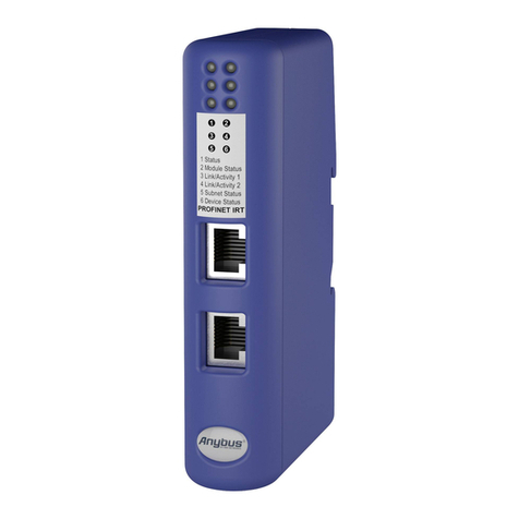
Front View
Bottom View
1
4
1
2
1
5
6
9
PC Connector
1. GND
2. GND
3. RS232 Rx
4. RS232 Tx Subnetwork Connector
1. +5V OUT
2. RS-232 Rx
3. RS-232 Tx
4. NC
5. Signal GND
6. RS-422 Rx+
7. RS-422 Rx-
8. RS-485+/RS-422 Tx+
9. RS-485-/RS-422 Tx-
Power Connector
1. +24 V DC
2. GND
Accessories Checklist
The following items are required for installation:
• Anybus Configuration Manager - Communicator RS-232/422/485
(available at www.anybus.com)
• RS-232 configuration cable
• Subnetwork connector
• PROFINET network cable and connector (not included)
Installation and Startup Summary
1. Mount the gateway on the DIN rail
2. Connect the gateway to the PROFINET network
3. Connect the gateway to the subnetwork
4. Power on the gateway
5. Connect the configuration cable between the gateway and
the PC containing Anybus Configuration Manager
6. Configure the gateway using Anybus Configuration Manager
7. Configure and start the PROFINET network
LED Indicators
LED Indication Meaning
1 (Network Status)
Off Offline
- No power
- No connection with IO Controller
Green Online (RUN)
- Connection with IO Controller established
Green, 1 flash Online (STOP)
- Connection with IO Controller established
- IO Controller in STOP state or IO data bad
- RT synchronization not finished
Green, blinking Node identification (see manual)
Red Fatal error
Red, 1 flash Station name error
Red, 2 flashes IP address error
Red, 3 flashes Configuration error
Alternating Red/Green Firmware update in progress
2 (Module Status)
Off No power or initializing
Green Normal operation
Green, 1 flash Diagnostic event present
Red Fatal error
Alternating Red/Green Firmware update in progress
3/4 (Link Activity)
Green Link OK
Green, flickering Transmitting/receiving data
Off Link not detected or no power
5 (Subnet Status)
Green, flashing Running, one or more transaction errors
Green Running
Red Transaction error/timeout or subnet stopped
6 (Device Status)
Off No power
Green Initializing
Green, flashing Running
Red Bootloader mode
Alternating red/green Configuration error
1
3
5
2
4
6
Network Status
Device StatusSubnet Status
LAN Port 1
LED Indicators
Link Activity 1
Module Status
Link Activity 2
LAN Port 2
LAN Connector (RJ-45)
1. TD+
2. TD-
3. RD+
4. (reserved)
5. (reserved)
6. RD-
7. (reserved)
8. (reserved)
1
8
