SECURECOM SC-GSM Owner's manual

Dcument revision: 5
S
SC
C-
-G
GS
SM
M
Universal GSM Gateway
and
Security Monitoring Service Emulation Device
Installing and programming
Manual
2017-02-02
-for version 3.14 and later-

Copyright © 016 - SECURECOM
Table o Contents
Table of Contents ....................................................................................................................................... 1
1.Short functional description of device .................................................................................................... 3
. Product Layout ................................................................................................................................... 4
3. Connection ......................................................................................................................................... 4
3.1 Power.......................................................................................................................................... 5
3. Emulated phone line .................................................................................................................. 5
3.3 Trigger inputs .............................................................................................................................. 5
4. Configuration of device .................................................................................................................. 5
4.1 Software connection .................................................................................................................. 5
4. Moving data between the PC and the device ............................................................................ 6
4.3 Device code lock (protection) ..................................................................................................... 6
4.4 Device Status .............................................................................................................................. 7
4.5 General setting ........................................................................................................................... 7
4.6 Transparent mode ...................................................................................................................... 8
4.7 Standalone mode ....................................................................................................................... 9
5. LED signals ........................................................................................................................................ 1
6. Most frequently used Contact ID codes .......................................................................................... 1

3
Copyright © 016 - SECURECOM
1.Short functional description of device
In Standalone mode the unit behaves like a monitoring station receiver which receives and handles
the CONTACT ID communication of alarm control devices. It compares the report codes with the filled
in event codes of the program table and at the occurrence of the desired event it sends the assigned
SMS message and initiates a call (siren sound is played). By this means the users of the alarm control
panel can be notified of any signals, differed by the event and subject of event (user, zone, partition).
Notifications are not limited to differ only few kind of events as it is usual with all other GSM (SMS)
communicators, with trigger inputs only. The best describing definition for this feature would be:
Converting Contact ID messages to programmable SMS messages and phone call notifications
Further function is that by controlling the contact inputs the communicator sends the assigned SMS
messages and calls the pre-set telephone numbers.
In transparent mode fully replaces phone line. By this means the alarm control panel can send the
report codes to monitoring station, or a simple phone device can be used on places where the phone
line is not available (elevators, SOS or INFO call points, weekend houses,…)
By controlling the contact inputs the communicator immediately sends the CONTACT ID messages
assigned to the inputs to the given monitoring station number and this way shorting down the
signaling time of the alarm state to monitoring station, providing more precious time to react, while
complete communication to monitoring station with full information of events in progress can take it’s
time.
Main features
•2 separate modes of operation in one device
•PSTN line simulation for monitoring station signal transmission
•SMS/CALL about 32 different kinds of C NTACT ID reports
•Signals to 4 telephone numbers
•2 contact inputs with independent signals SMS/CALL
•Handling SIM PIN code
•Forwarding SMS
•Setting and diagnostics via USB connection
Technical specifications
• Power 9-30V (DC)
Power consumption 300mA (max.) / 100mA (idle)
• Telephone line data
Line voltage 48V
Loop current 25mA
Load impedance 100-470 hm
Dial tone 425Hz
• perating temperature 0…+70°C
• Size 40x75x15mm

4
Copyright © 016 - SECURECOM
2. Product Layout
3. Connection
In order to operate properly, the device must be equipped with a valid SIM card and the
external antenna must be connected to the antenna connector. Use the supplied antenna
or any other GSM antenna that suites the needs for installation. The SIM card should be
inserted to the card holder “door” (the moving part of card holder), as shown on picture.
The Door must be pushed toward the PCB until completely “closed”, i.e. the two parts of
card holder are overlapping, and after that the card holder should be L CKED, by puling
the holder ”door” toward the terminals (as marked on the holder). The locking of card
holder gives a click sound. If the card was not placed as it should be, the card holder door
can not be locked and turning the PCB in horizontal position with card holder toward the
ground will cause the holder to open. In this case, the device will not operate properly,
and may cause the damaging of SIM card. Please be sure that the SIM card is placed
properly before powering up the device.
Warning: The SIM card should never be removed or added while the device is
powered up.
USB connection
to connect to PC USB port and then the setting PC
program of the communicator storage can be started
Antenna connector
GSM 900/1800MHz antenna with SMA connector
LED indicators
SIM holder
Simulated PSTN landline output (T/R)
Contact inputs to be for COM, negative
voltage
Power supply input

5
Copyright © 016 - SECURECOM
3.1 Power
Securecom communicators can be powered from USB connection for checking,
programming or basic operation of device. However, the external power (connected to
terminals +12V and COM) is required for proper operating, especially during the DATA
WRITE procedure, i.e. uploading of data through the USB connection. The device will be
functional with any power voltage between 9 and 30 V DC is applied to the terminals.
3.2 Emulated phone line
The TIP and RING terminals of the Securecom device provides an emulated phone line.
Connect these terminals where the PSTN (regular phone line) is supposed to be connected
to the device that will use this communicator. In case of connecting to alarm panel, use
the INC MMING LINE terminals, (usually marked with TIP/RING or T/R, or Ti/Ri...). The
UTG UNG line terminals (usually marked as Tip1/ring1, or T1/R1, or To/Ro) can be used
as described in manual for alarm panel ( to connect a phone, or other device), but no
voice calls can be made or received on this connection. nly the “line signal” is available.
3.3 Trigger inputs
There are 2 C NTACT inputs on device, marked as Z1 and Z2. These inputs are used to
trigger a voice call to a user, send a SMS message, or to send a specified Contact ID code
to a monitoring station ( when device is set to transparent mode). These inputs are
triggered when connected to the COM, i.e. to the supply negative line. When connecting
the device to an alarm panel, if the power is supplied from alarm panel ( connected to it’s
AUX terminals) these inputs can be directly connected to PGM outputs of alarm panel,
that are “open collector” type, since when activated, these outputs provide a shortcut to
the panel ground. With such connection, no other wiring is required. If the PGM is REELAY
type (two connection points), than one pole of the output relay must be connected to the
same place with the communicator COM terminal, and the other to Z1 or Z2, in balance
with programming.
. Configuration of device
Connect the device with USB cable to a windows PC (Compatibility: Windows 7, 8.1, and
10) , and a new drive will be installed. When connected to that machine for first time, the
driver will be installed first, then the new drive will be found. This drive is the flash
memory of Securecom device, and contains the software and this manual. You can run the
software from device, or copy it to your PC and run it from there. When the device is
powered through terminals, the USB cable can be plugged or unplugged at any time, it will
not affect the device. The windows machine might require a proper closing of USB
connection before unplugging the cable.
4.1 Software connection
If the device is L CKED or a wrong type of device is connected on USB port, the
PASSW RD field is displayed. If a wrong password is entered, the software will display the
status fields only Settings are not displayed and can not be changed. This mechanism
prevents unauthorized access to device settings.
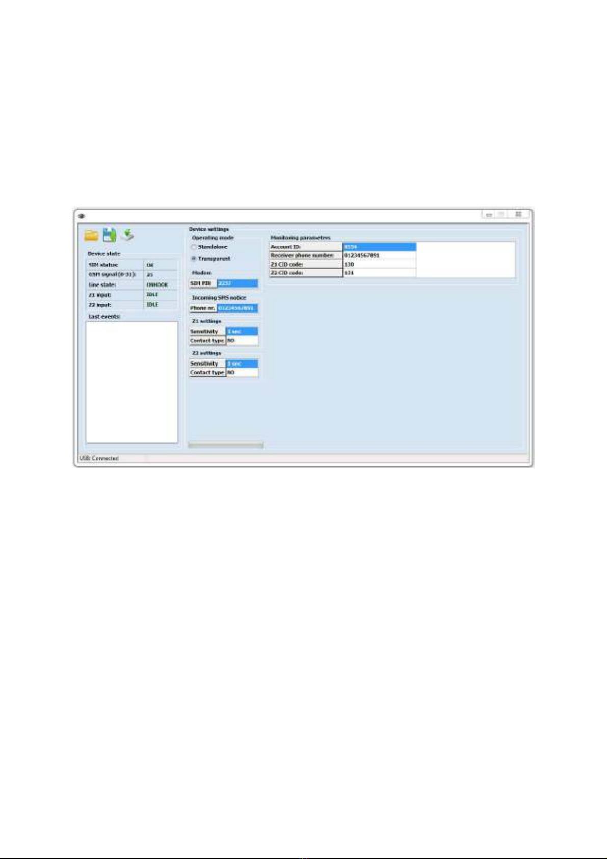
As the software successfully connects to the device, it reads out the device and shows the
status, device version and actual settings in device (marked red on following picture):

6
Copyright © 016 - SECURECOM
In case that software does not show a “connected” status or the firmware version, the USB
connection was not made properly. Please select a different USB port check the USB cable.
If the problem persist, the device USB driver might be in conflict with some other driver in
windows, check the device manager or try the connection on another machine.
If the software and connected device are not the same TYPE ( GSM/GPRS), it will result
bad operation- programming errors and device malfunction. Therefore, after
connecting the device to the software, ensure that the software and the
device firmware are the same TYPE (GPRS setup, and GPRS firmware)!
4.2Moving data between the PC and the device
Reading out data from the device happens automatically as soon as connection is
established. Settings can be saved to PC or loaded from PC file. These icons are used to
handle the settings data:
(File_reading / File_saving / Upload to device
IMPORTANT NOTICE: if a new settings file is loaded or ANY setting is modified on
software screen, all data needs to be uploaded onto the device. You can make all required
changes in software, and then upload data. Changes that were not uploaded will be
terminated when the software is closed or the connection is cut cable unplugged).
4. Device code lock (protection)
The device can be locked with a security code. By default, there is no code but once
entered, the code will be required for each connection. After connecting, the new code can
be entered with the icon:
After connecting via USB, if the device was set with a code, the software requests
to enter the device code. If you cancel the code entry, the software will display only the
status and no settings can be red or edited. After closing re-starting the software, the code
entry box is displayed again. nly after the right code was entered, the software will be
fully functional, presenting the whole window with all settings displayed and editable.

7
Copyright © 016 - SECURECOM
WARNING: If the code is lost or forgotten, only way to access to device setting is
with FACTORY DEFAULT. For that procedure, the device must be sent to
appropriate service
4.4 Device Status
The left side of the software window is showing the device status. This part is
ALWAYS VISIBLE, even when the device is protected with code lock. These are the
fields in the status view:
4.5General setting
The General setting parameters are valid for both operating modes, and in this area the operating
mode (transparent or standalone) is selected
Field name Options (description)
SIM status
Waiting / OK / PIN request (Connecting to GSM network / OK / PIN
requested)
GSM signal A value between 0 and 31, 16 is minimal for reliable functionality
Line state ONHOOK / OFFHOOK (emulated phone line idle / active)
Z1 input state IDLE / ACTIVE (Input Z1 idle / active)
Z2 input state IDLE / ACTIVE (Input Z idle / active)
Communicational event messages:
Dialed The number dialled by the alarm control panel
CID The CONTACT ID code sequence sent by the alarm control panel
Z1 Event Activated input one
Z1 Restore Input one got back to default
SMS sending Sends the SMS messages belonging to the event
CA (1) Calls the first set number
DTMF recd. got DTMF code, that is acknowledgement from the notified number
USB Status of USB connection (Connected or Disconnected)
Field name Options (description)
Operating mode TRANSPARENT operating mode (chapter 3.6)
STANDALONE operating mode (chapter 3.7 )
PIN code PIN code of the SIM card must be entered here if the card is set to request
a PIN. If a wrong PIN is entered, the device will „lock” the PIN card by trying
to activate the SIM with entered code, over and over. After 3 unsuccessfull
PIN code entries, the SIM requires a PUK code. This code must be entered
with a different device (mobile phone)
Incomming SMS notice Incomming SMS messages will be forwarded to the given telephone number
Z1 input setting the sensitivity and type of contact input Z1
Z2 input setting the sensitivity and type of contact input Z2
Fields available in Standalone mode ONLY:
Phone numbers user phone numbers where the unit can send the signal in the
form of SMS and/or call (to maximum 4 numbers).
ACK If the ACK field is selected next to a number, the device requests
an acknowledge signal for every call made to this number.
Acknowledge signal is any DTMF signal ( any number from
telephone keypad). If the acknowledge is not received, the call is
repeated until the acknowledge is made, but maximum 3 times. If
the Acknowledge is received, all further calls for that event are
terminated. This means that the called party who acknowledges
the call will STOP the calls to numbers that are next in order (T1/T4)

8
Copyright © 016 - SECURECOM
4.6Transparent mode
In this mode, device can be used as a transparent GSM Gateway, to forward signals
(sounds) from a phone device or alarm panel through a GSM network, to called party or a
monitoring station receiver. The phone device (alarm panel) connected to the RING/TIP
terminals make the dialing, the Securecom device just dials that number, and opens the
V ICE channel to transfer all sounds in high quality through GSM network. In case of
incomming call, the device will generate a RING signal on his emulated phone line, toward
phone device or alarm panel.
Z1 and Z2 contact inputs are used as inputs of independent alarm communicator,
triggering them causes the sending of programmed event code (Contact ID protocol) to
the programmed Receiver Phone Number, paired with the programmed Account Id.
The partition number in the message is 01 and the value of the zone in the message is
001 and they cannot be changed. Communication format is C NTACT ID. You can find the
requested Contact ID code in the Chapter 6, or the “Contact-ID-codes-with-
explanation.PDF” file.
The best example of usage of these inputs is when the securecom is used with alarm
panel, to send a QUICK signal of an alarm state, while the dialer in alarm panel slowly
makes the complete reporting of complete events through the emulated phone line. To
achieve this, it is enough to connect a PGM or BELL output from alarm panel to a zone
input, along with ring/tip lines and the AUX (power supply) wires.

9
Copyright © 016 - SECURECOM
4.7Standalone mode
This mode is used to send notifications and informations from alarm panel directly to
USERS. When a alarm panel transmits a selected Contact ID event Code (through
emulated phone line on ring/tip terminals), Securecom device simulates a receiver,
accepts the code and confirms the event reception to alarm panel. After that, the
received Code is compared to all codes set in the „Alarm Event Handling”, and if it
exists in the tabble, the communicator makes the programmed procedure- starts a voice
call or sends SMS messages to selected user numbers (1-4). The two inputs do the set
procedure same way, but activated with an external triger (contact).
In this mode the device expects to receive signal in the format defined by the C NTACT ID
standard. The Contact ID Message is defined this way:
SUBSCRIBER
ID
XXXX
EVENT
QUALIFIER
Event or
Restore
EVENT CODE
XXX
PARTITION
XX
ZONE or USER
XXX
8556 1 01 01 001
In the example , the received Contact ID code /8556 18 1 01 01 001/ means that a
system with ID number (“account number”) 8556, has sent a signal that EVENT (1) of
ARMING ( 01) was made in Partition 01, by user 001. With settings as shown on
picture on top of this page, Appropriate SMS message for this code ,”ANGIE left home”
(Angie is user 001), will be sent to sent to T1 telephone number.
Another example: When the alarm occurs in zone 2 of the alarm system, the code 8556
18 1 130 01 002 will be transmitted, and the Securecom device will call the phone
numbers T1 ( 01234567891) and expect the ACKN WLEDGE from the called party (any
button on dialer pressed) will be expected. After that, the T2 ( 01234567892) will be
called, and after that the “Burglary in the Hall!” text message will be sent to these two
numbers.

10
Copyright © 016 - SECURECOM
Setting the signaling in standalone mode:
Each line of the table should be set like this:
Code E/R Part Zone /
User
C1,C2,C3,C SMS
message
S1,S2,S3,S
3 digit
CID code
E: event
R: restore
digit
partition code
3 digit zone or
user code
Telephone
numbers (T1-T4)
designated to
voice call
SMS
message to
be sent if a
code occurs
Telephone
numbers (T1-
T4) designated
to SMS sending
If the received Contact ID Code fits the setting in one line of the table, the Securecom
will perform the procedure of calls and messages as set in that line. Each line is
independent from another. You can use the same Code in several lines, if any of other
“filters” that are used for the received code comparation (E/R, Part, Zone/User) differ
from each other.
1. The code comparation:
Code: Contact ID code that should be received in the Contact ID message from
alarm panel, in order to make the procedure that is defined in same line of the
table. You can find the requested Contact ID code in the Chapter 6, or the
“Contact-ID-codes-with-explanation.PDF” file.
E/R: Event or restore of the event defined by the code, along with the C DE it
presents the event that is being transmitted. For example 1-130 is Event for
Burglary alarm, and the 3-130 is REST RE of Alarm state (zone closed or
system dissarmed). Also 1-401 means ARMING, while 3-401 means
DISARMING.
Part: The Partition number that should be received in the Contact ID message from
alarm panel in order to perform the procedure defined in that line of the table.
If this field was left empty, the “partition filter is off”, so the device will not
check the Partition number in the received Contact ID message, and the
procedure will be performed for ANY partition signal, if the rest of receive
message fits the settings.
Zone/User: The Zone or User number that should be received in the Contact ID
message from alarm panel in order to perform the procedure that is defined in
that line of the table. If this field was left empty, the “zone filter is off”, so the
device will not check the Partition number in the received Contact ID message,
and the procedure will be performed for ANY partition signal, if the rest of
receive message fits the settings.

11
Copyright © 016 - SECURECOM
2. The procedure that will be performed if the received message fits the values
in table:
C1-C : The marked field means that that phone number will be called if the received
message fits the setting for the code comparation. The C1 means „call phone number 1”,
C2 means „call number 2”, etc. If the field is left empty, that number will not be called
even if the received message fits the setting for the code comparation. The „ACK” field
next to number affects the call order. Please refer to field explanation on chapter 4.5
„General setting” (page 7), or the „imortant Notices” below.
SMS Message: The text that will be sent to the selected numbers when the received
Contact ID message fits the setting for the code comparation.
S1-S : The marked field means that that the set text will be sent in the SMS message
to that phone number if the received message fits the setting for the code comparation.
The S1 means „Send message to phone number 1”, S2 means „Send message to number
2”, etc. If the field is left empty, message will not be sent to that number even if the
received message fits the setting for the code comparation.
Important Notices:
•The procedure will be performed in following order : first the SMS messages are sent
to all required numbers, after that the required calls are made, in numeric order from
T1 to T4). If the acknowledge from some number is required, that call will be repeated
until acknowledged or timed out. The next call will be made only after time out.
•Acknowledge confirms call to THAT number and stops all other calls for that event that
are following in order 1-4).
•Maximum duration of call is 20 seconds including the ring time. If the acknowledge is
received, the call is immediately finished.
•If „ACK” reception acknowledgement is set and the acknowledge signal is not received
during the call time, the device will end the call and repeat the call, maximum three
times. After that the call is timed out and next call is made.
•When a number is called, a SIREN SOUND is played, until the end of call.
• If Part partition) or Zone/User zone/user) is left blank, that value in the Contact
ID message will be disregarded, the securecom will make the calls and sent the
messages that are set in this line, no matter what value was sent by alarm panel if
the other fields fit the received message)

1
Copyright © 016 - SECURECOM
5. LED signals
The LED signals show the communicator’s operating state. Following the LEDs on device,
you can see the momentary situation i.e. the status.
NORMAL OPERATION
If some fault is valid, red TR UBLE will lit continuously, while green LED shows the cause
of the fault with blinks
GSM NETWORK FAILURE
6. ost frequently used Contact ID codes
120
Panic
130
Burglary
144
Sensor tamper
300
System Trouble
301
AC Loss
302
Low system battery
311
Battery Missing/Dead
316
System Tamper
321
Bell 1
383
Sensor tamper
401
Arm/disarm by user
602
Periodic test report
626
Time/Date trouble
627
Installer programming
Other manuals for SC-GSM
1
Table of contents
Other SECURECOM Gateway manuals