Lindsay Broadband LB-1310TC Series User manual

LB-1310TC Series (V1.2)
1310nm Optical Transmitter
User Manual

2035-2 Fisher Dr., Peterborough, ON CANADA K9J 6X6 Ph: (705) 742-1350 or (800) 465-7046 Email: contactus@lindsaybroadbandinc.com
ii
LB-1310TC Series
User Manual
TABLE OF CONTENTS
TABLE OF CONTENTS ................................................................................................................ii
1.0 PRODUCT OVERVIEW & FEATURES ......................................................................... 1
1.1 Description...................................................................................................................... 1
1.2 Features .......................................................................................................................... 1
2.0 SAFETY NOTES ............................................................................................................... 2
3.0 LB1310TC SERIES FUNCTIONAL BLOCK DIAGRAM.............................................. 3
4.0 LB1310TC SPECIFICATIONS ........................................................................................ 3
5.0 FRONT & REAR PANEL DESCRIPTION...................................................................... 4
6.0 INSTALLATION.................................................................................................................. 5
6.1 Required Equipment & Tools ....................................................................................... 5
6.2 Installation of Transmitter ............................................................................................. 5
7.0 LCD DISPLAY & MENU FUNCTIONS........................................................................... 7
7.1 System Initialization ...................................................................................................... 7
7.2 System Menu ................................................................................................................. 8
7.3 Voltage Menu ................................................................................................................. 8
7.4 Laser Menu..................................................................................................................... 9
7.5 RF Menu ......................................................................................................................... 9
8.0 SNMP FUNCTIONALITY ............................................................................................... 10
8.1 RJ45 Communication Interface................................................................................. 10
8.2 WEB network management functions .......................................................................11
8.3 Simple Network Management (SNMP) functions................................................... 12
9.0 WARRANTY & RMA POLICY........................................................................................ 13

2035-2 Fisher Dr., Peterborough, ON CANADA K9J 6X6 Ph: (705) 742-1350 or (800) 465-7046 Email: contactus@lindsaybroadbandinc.com
1 | P a g e
LB-1310TC Series
User Manual
1.0 PRODUCT OVERVIEW & FEATURES
1.1 Description
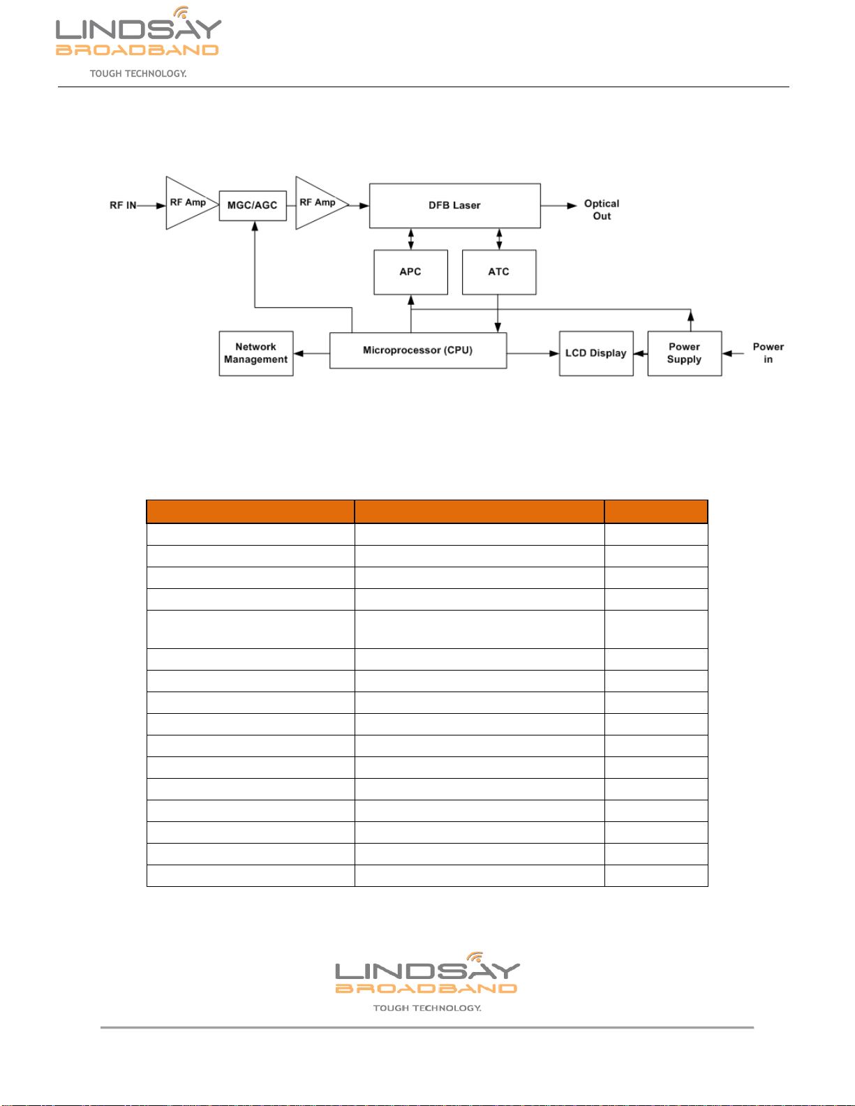
Lindsay Broadband LB-1310TC series of 1RU rack mount optical transmitters are high linearity,
low noise 1310 nm high performance direct modulated DFB optical transmitters. The LB-
1310TC use high performance DFB direct modulated lasers, with single optical output powers
from 4mw to 20mw, in 2mw steps. RF broadband input (47 – 1000MHz) is directly modulated
into 1310 nm DFB laser via pre-distortion circuit for optimum distortion and noise performance.
Auto output laser power stability control (APC) and auto laser temperature control (ATC) are
standard features. The LCD front panel display is used to monitor all functional transmitter
parameters; output laser power, laser temperature, laser bias current, cooling current, power
supply voltages, MGC/AGC state and OMI value. The LB1310TC is equipped with an RJ45
communication interfaces for system network management. Optional redundant power supply
module is available upon request.
1.2 Features
1RU standard rack mounted case
High performance DFB laser with narrow spectrum and good linearity.
1310 ± 20 nm wavelength
Available Output power (4mw to 20mw in 2mw steps)
47 – 1000MHz RF input with AGC
100 – 260 VAC (50 to 60Hz) powering
APC and ATC control circuits
Built-in Microprocessor monitors laser performance
Front panel LCD display, displays all functioning parameters

2035-2 Fisher Dr., Peterborough, ON CANADA K9J 6X6 Ph: (705) 742-1350 or (800) 465-7046 Email: contactus@lindsaybroadbandinc.com
2 | P a g e
LB-1310TC Series
User Manual
2.0 SAFETY NOTES
NO SERVICEABLE PARTS INSIDE. REFER SERVICING TO QUALIFIED SERVICE PERSONNEL.
•The LB1310TC employs an infrared laser device that emits invisible light, which
can permanently damage the retina of an eye.
•Avoid direct exposure to the laser light source.
•Never stare directly into a fiber or at any mirror-like surface that could reflect
light emitted from an un-terminated fiber.
•Never view an active fiber through optical instruments.
•Always ground the transmitter before turning on power (grounding
resistance should be less than 4 ohms), so as to prevent laser and user
from static damage.
2035-2 Fisher Dr., Peterborough, ON CANADA K9J 6X6 Ph: (705) 742-1350 or (800) 465-7046 Email: contactus@lindsaybroadbandinc.com
3 | P a g e
LB-1310TC Series
User Manual
3.0 LB1310TC SERIES FUNCTIONAL BLOCK DIAGRAM
4.0 LB1310TC SPECIFICATIONS
PARAMETER
SPECIFICATION
UNIT
RF input Bandwidth
47- 1000MHz
MHz
Flatness
±0.75
dB
RF Input level w/AGC control
18
dBmV
AGC Control
Input level ± 5
dB
Return Loss
≥16 (47-550MHz); ≥14 (550-
1000MHz)
dB
CTB
≥65
dB
CSO
≥60
dB
C/N
≥51
dB
Optical Wavelength
1310±20
nm
Optical Power
4-20 (in 2mw steps)
mW
Optical Connector
SC/APC or FC/APC
Optical Fiber Type
Single Mode
Voltage
100 - 260VAC (50 to 60Hz)
VAC
Power Consumption
≤ 30
W
Dimension:
480 × 320 × 44 (W×D×H)
mm
Weight
≤5
kg

2035-2 Fisher Dr., Peterborough, ON CANADA K9J 6X6 Ph: (705) 742-1350 or (800) 465-7046 Email: contactus@lindsaybroadbandinc.com
4 | P a g e
LB-1310TC Series
User Manual
5.0 FRONT & REAR PANEL DESCRIPTION
The front panel display allows you to monitor the transmitter parameter; (ie. output laser power
(mw), the laser bias current (mA), temperature (℃), cooling current (mA), and RF Level) and
power supply parameters of +24V, +5V, and -5V.
At this point check the parameters using the Menu Button.
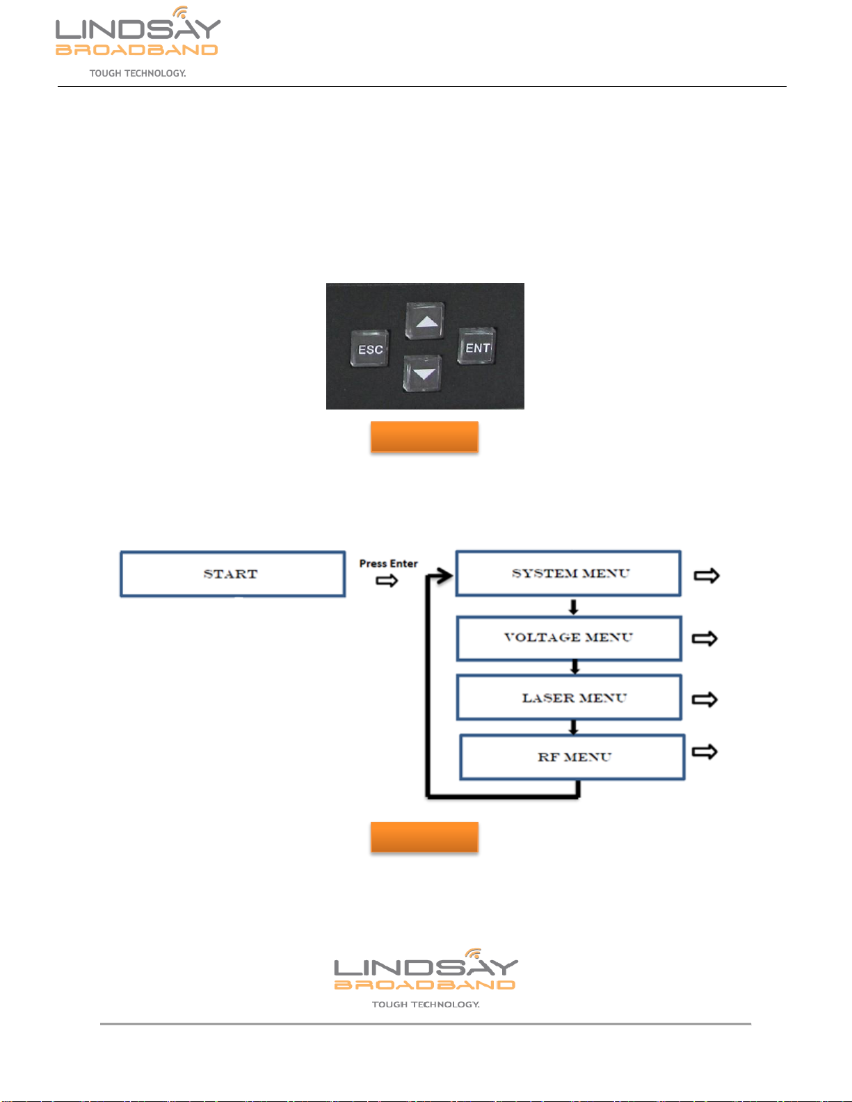
Menu Buttons:When the menu buttons “ENT” is pushed, it will show the various menu options
to choose from. After a period of inactivity (approx. 30 seconds) the backlight display will shut
off and directed to Home Screen. Push the “ , ” menu buttons to browse through or change
the transmitter parameters. Press “ENT” menu button to select any parameter or enter any
menu/sub-menu. Press “ESC” menu button to exit out of any parameter or menu/sub-menu.

2035-2 Fisher Dr., Peterborough, ON CANADA K9J 6X6 Ph: (705) 742-1350 or (800) 465-7046 Email: contactus@lindsaybroadbandinc.com
5 | P a g e
LB-1310TC Series
User Manual
6.0 INSTALLATION
6.1 Required Equipment & Tools
Digital multimeter
Optical power meter
Cable TV RF meter or spectrum analyzer
Standard fiber test jumper
Denatured or 99% pure isopropyl alcohol and lint free fiber optic cleaning wipes
6.2 Installation of Transmitter
1) Installation of the LB-1310TC should be in a controlled environmental Hub or Closure to
avoid excessive temperature and humidity.
2) UPS power supply and an air conditioned environment are highly recommended for
stable and long-time transmitter operation.
3) Install the transmitter in the 19” rack. Leave ½ inch of space between the transmitter and
other equipment installed in the rack for proper heat dissipation.
4) Ensure the LB-1310TC is grounded and is mounted in a properly grounded rack,
grounding resistance should be smaller than 4Ω. Always ground the transmitter before
turning on power, so as to prevent laser and user from static damage.
5) Ensure optical jumper connectors are matched properly to the device adapters. (ie.
SC/APC to SC/APC).
6) Carefully clean all the fiber optic connectors. The suggested way of cleaning a fiber optic
connector is to use a dedicated and dry cloth (Kimwipes ®’s fine cloth).
7) A microscope (at 100 times, 200 times) can be used to check the cleanliness of fiber
optic connector surface from any contamination or blemish.
8) Clean the LB-1310TC connector before installing the optical test cable. 2.5 mm cleaning
swabs are available. Connect the fiber to the LB-1310TC.
9) Using a digital multi-meter, verify the input voltage is in accordance with power
requirements. Then turn on power.

2035-2 Fisher Dr., Peterborough, ON CANADA K9J 6X6 Ph: (705) 742-1350 or (800) 465-7046 Email: contactus@lindsaybroadbandinc.com
6 | P a g e
LB-1310TC Series
User Manual
10) Checking the LCD display verify that the System Initialization is in process.
11) After initialization press the “ENTER” menu buttons to query the parameters of the
transmitter.
12)Connect the fiber test cable and optical power meter to the transmitters optical output.
Measure the optical output power and confirm it is the same or close to the value
displayed on the LCD display. Ensure the optical power meter is set for 1310 nm
wavelength and that the fiber test jumper is clean.
13) Again, Clean the LB-1310TC connector before installing the optical cable. 2.5 mm
cleaning swabs are available. Connect the fiber to the LB-1310TC.
14) Measure the input RF signal level with a Signal level meter or a spectrum analyzer.
Make sure the RF signal level is in the range of 15 dBmV and 25 dBmV (Optimum value
is 20 dBmV). You can now connect the RF signal to the RF signal input port of the
equipment. With the proper RF signal input the Laser LED lamp will turn from Red to
Green.
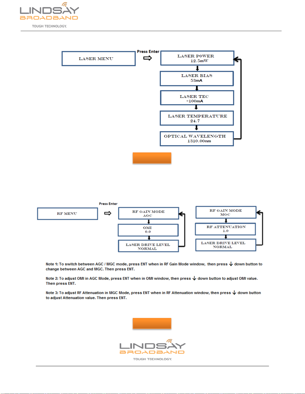
15) RF AGC/MGC: Follow the RF menu to adjust the RF attenuation if required. It is
recommended to put the transmitter into Automatic Gain Control (AGC) mode. Test point
is -20 dB below the RF input level.
16) The OMI (Optical Modulation Index) is factory set for 3.5% OMI based on 79 NTSC
channels and digital channels 6db level offset above 550MHz. This adjustment should
not be touched unless done in a laboratory environment with proper equipment to
measure OMI.
2035-2 Fisher Dr., Peterborough, ON CANADA K9J 6X6 Ph: (705) 742-1350 or (800) 465-7046 Email: contactus@lindsaybroadbandinc.com
7 | P a g e
LB-1310TC Series
User Manual
7.0 LCD DISPLAY & MENU FUNCTIONS
7.1 System Initialization
Power up device, the LCD panel will show “LB-1310TC-xx” (xx is the output power in milli-
watts). You then can use the Menu buttons to navigate through the different menus. There are
4 menus that you can use to monitor the transmitter parameters, and adjust some parameters.
See Figure 2.
Figure 1
Figure 2

2035-2 Fisher Dr., Peterborough, ON CANADA K9J 6X6 Ph: (705) 742-1350 or (800) 465-7046 Email: contactus@lindsaybroadbandinc.com
8 | P a g e
LB-1310TC Series
User Manual
7.2 System Menu
7.3 Voltage Menu
Figure 3
Figure 4
2035-2 Fisher Dr., Peterborough, ON CANADA K9J 6X6 Ph: (705) 742-1350 or (800) 465-7046 Email: contactus@lindsaybroadbandinc.com
9 | P a g e
LB-1310TC Series
User Manual
7.4 Laser Menu
7.5RF Menu
Figure 5
Figure 6

2035-2 Fisher Dr., Peterborough, ON CANADA K9J 6X6 Ph: (705) 742-1350 or (800) 465-7046 Email: contactus@lindsaybroadbandinc.com
10 | P a g e
LB-1310TC Series
User Manual
8.0 SNMP FUNCTIONALITY
8.1 RJ45 Communication Interface
Standard RJ45 head as connector pin is defined as follows:
1:TX+ 2:TX- 3:RX+
4:No Connect 5:No Connect 6:RX-
7:No Connect 8:No Connect
A: green indicator light indicates when the network connection is normal
B: yellow light flashes to indicate the LAN port is sending data
Select port which is connected to LB-1310TC transmitter and click “OK”
2035-2 Fisher Dr., Peterborough, ON CANADA K9J 6X6 Ph: (705) 742-1350 or (800) 465-7046 Email: contactus@lindsaybroadbandinc.com
11 | P a g e
LB-1310TC Series
User Manual
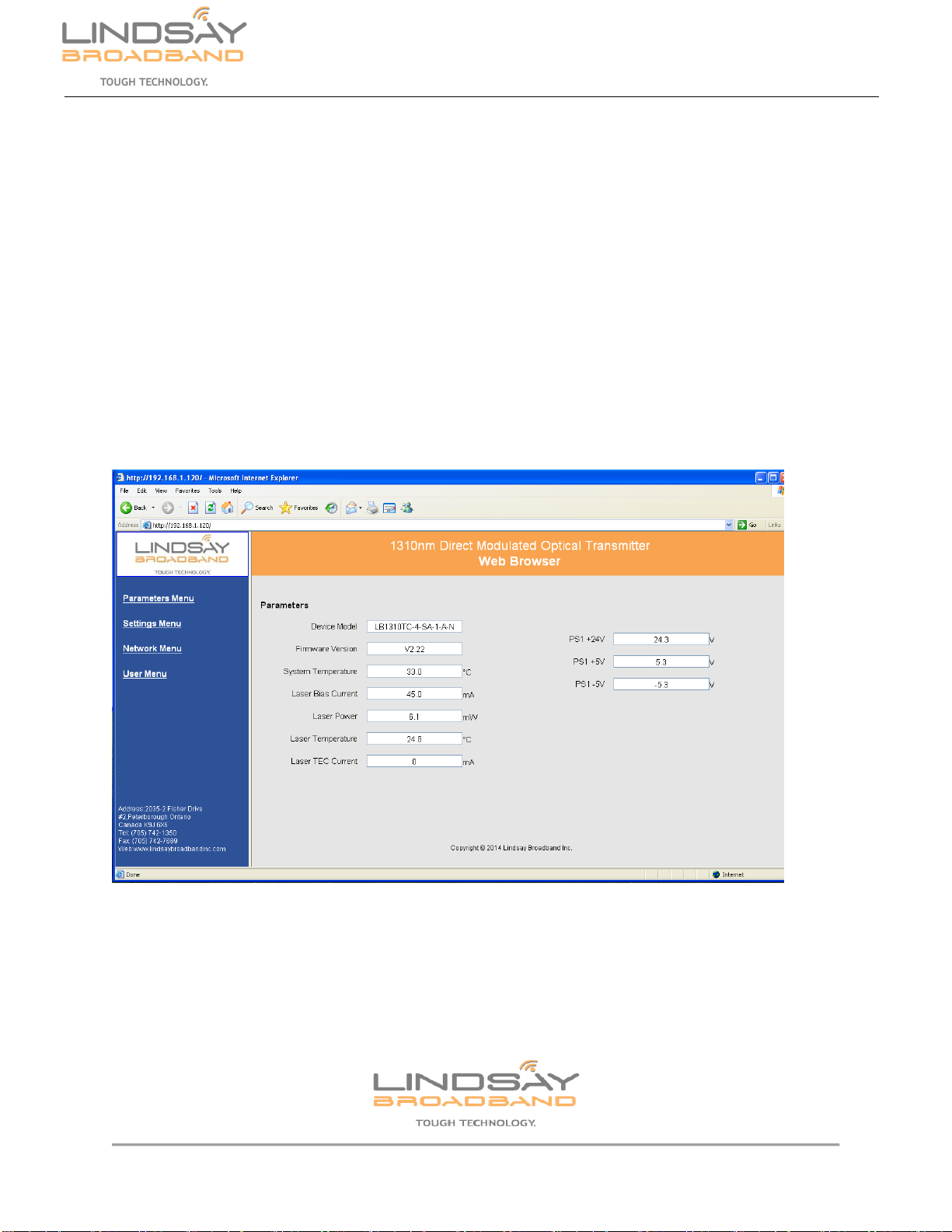
8.2 WEB network management functions
Connect the optical transmitter with a network cable to the PC RJ45 interface. Factory network
parameters of the optical transmitter:
IP: 192.168.1.120 Mask: 255.255.255.0 Gateway: 192.168.1.1.
WEB NMS factory default login password is "1234."
Open a Web Browser. In the address bar enter 192.168.1.120, Press Enter, enter the login
password in the login screen pop up to access the device web interface, display as shown
below.
The navigation menu is to the left of the page. Click on the required menu. The transmitter
content is displayed for the corresponding menu chosen.
2035-2 Fisher Dr., Peterborough, ON CANADA K9J 6X6 Ph: (705) 742-1350 or (800) 465-7046 Email: contactus@lindsaybroadbandinc.com
12 | P a g e
LB-1310TC Series
User Manual
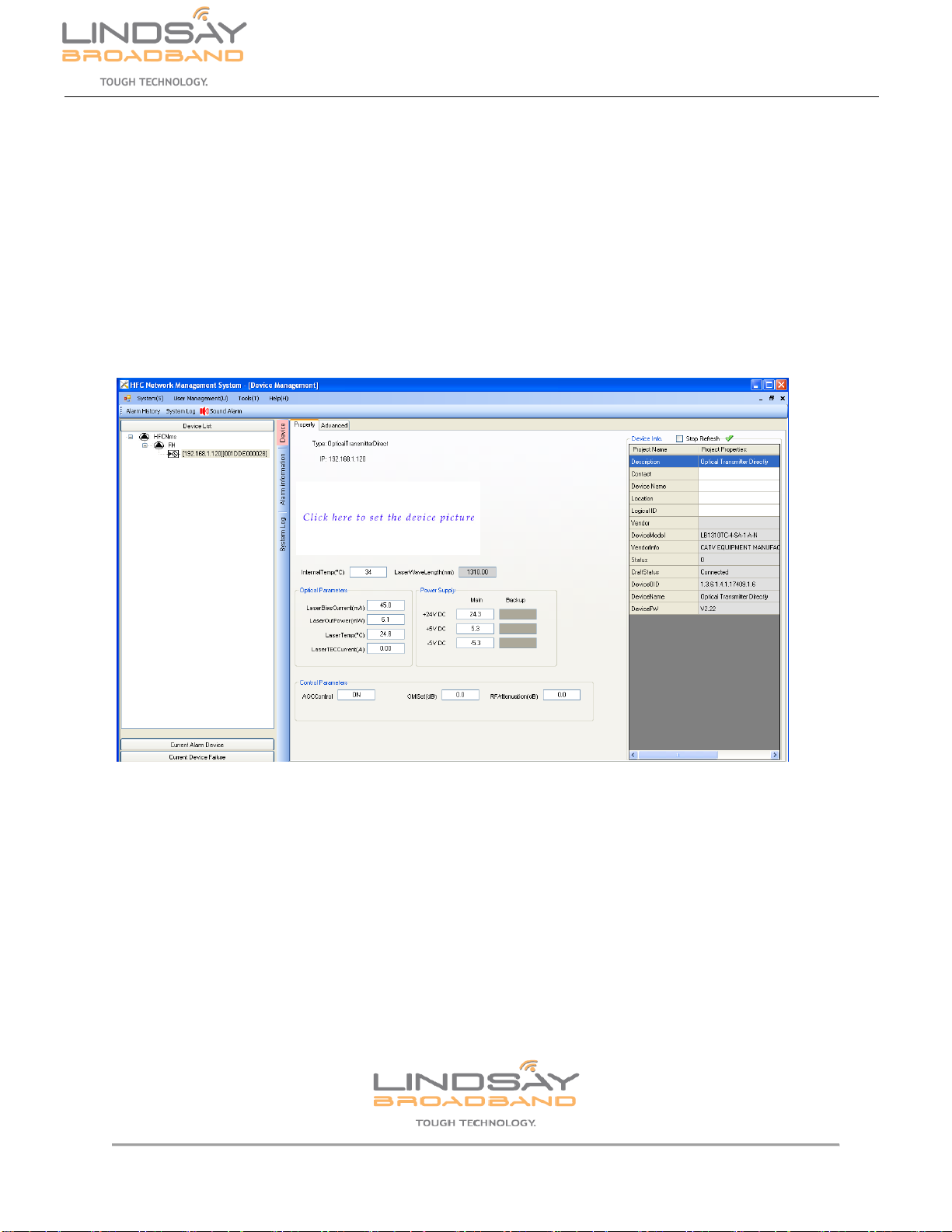
8.3Simple Network Management (SNMP) functions
Simple Network Management function application packet layer protocol is SNMPv1 that
supports the operation of SNMP commands.
Proprietary MIB repository of information related to the transmitter can be found "HFC network
equipment management system standard" and the NMS software for real-time parameters and
configuration of the transmitter. The following screen shot is an optical transmitter on the
network management system.

2035-2 Fisher Dr., Peterborough, ON CANADA K9J 6X6 Ph: (705) 742-1350 or (800) 465-7046 Email: contactus@lindsaybroadbandinc.com
13 | P a g e
LB-1310TC Series
User Manual
9.0 WARRANTY & RMA POLICY

2035-2 Fisher Dr., Peterborough, ON CANADA K9J 6X6 Ph: (705) 742-1350 or (800) 465-7046 Email: contactus@lindsaybroadbandinc.com
14 | P a g e
LB-1310TC Series
User Manual
Lindsay Broadband Return Material Authorization Policy
Send your returns to:
Lindsay Broadband Inc.
2035-2 Fisher Dr.
Peterborough, ON Canada K9J 6X6
Attn: Product Returns
All shipments are to be pre-paid by the sender. No COD’s will be accepted.
A Return Material Authorization (RMA) Number is Required On all Product Returns
(Regardless if Product is Being Returned to Repair or credit)
Product Received at the Lindsay Broadband Factory
Without an RMA Number will be Returned to Sender
RMA number must be used when returning product for credit or repair. Use of RMA numbers
will ensure efficient processing. When returning product to Lindsay Broadband, please follow the
simple steps below (in the order that they appear):
RETURNS
1. Fill out the Product Return Authorization Form indicating product information. Repair items do not require original invoice
information, but it is helpful to determine warranty eligibility.
2. Contact Lindsay Broadband Inc. Service Department in one of three ways:
E-mail to: [email protected] (recommended method) Include all of the information from the
product Authorization Form, or,
Fax the Product Authorization Form to 1-705-742-7669 or,
Call Lindsay Broadband Inc. @ 800-465-7046 Ext 235 / 261
3. After completing Steps 1 & 2, an RMA number will be assigned to you.
4. Securely pack the product and mark the box with your RMA #. If shipping multiple boxes, all boxes should be marked with
the RMA #. The RMA # must be placed near your return address in large, bold print (approximately 2” in height). Please see
the address label below as an example of the relative size location of the RMA #.
Sample Address label with RMA #
John Smith
ABC Company RMA 1234
123 Smith Street
Anytown, USA 00000
Lindsay Broadband Inc
2035 Fisher Dr.,
Peterborough, ON K9J 6X6
Attn: PRODUCT RETURNS

2035-2 Fisher Dr., Peterborough, ON CANADA K9J 6X6 Ph: (705) 742-1350 or (800) 465-7046 Email: contactus@lindsaybroadbandinc.com
15 | P a g e
LB-1310TC Series
User Manual
Lindsay Broadband Return Material Authorization (RMA) Form
Company
Contact Name:
Address:
City:
Prov/State:
Postal Code/Zip:
Phone: #:
Fax #:
Email address (if applicable)
RMA #
(To be supplied by Lindsay Broadband)
Date: ___________
Reason for return
Qty.
LBI Part #
Description
P.O. #
P.O.
Date
Service Repair Policy
Lindsay Broadband product may be
returned for repair under the following
condition:
1. Please contact Lindsay Broadband
Service Dept. to obtain an RMA#.
2. Please supply requested
information to verify 2warranty
coverage.
Any shipments received by Lindsay
Broadband without an RMA # will be
refused.
Credit Return Policy
Lindsay Broadband products may be
retuned for credit under the following
conditions:
1. Products are unused and
undamaged.
2. Products are accompanied by a one
dollar (new purchase) for one
dollar (credit return) order.
3. Products were purchased within on
year from credit return date and are
in a current catalog.
4. Products are subject to a 10% per
RMA and $2.00 per line item.
5. Products that are custom made are
subject to an additional charge for
conversion of not less than 20%
and not more than 50% of the FFP
price.
6. Product that require factory
repacking are subject to an
additional charge for material and
labour.
7. Please contact Lindsay Broadband
Customer Service to obtain an
RMA#.
Any shipments received by
Lindsay Broadband without
an RMA# will be refused.
Note: Products that are judged by
Lindsay Broadband Inc. upon receipt as
being unacceptable for credit shall be
returned to sender at their expense.
SHIPPING INSTRUCTIONS
1. Make Sure to Obtain an RMA# and
mark a box(s) accordingly
2. Ship Only Items Authorized
3. Enclose Packing Slip & Product
Return Authorization Form
4. Ship Prepaid Only to :
Lindsay Broadband Inc
2035-2 Fisher Dr.
Peterborough, ON CANADA
K9J 6X6
Attn: Product Returns
Table of contents


