LINEAR LEDS LTL.BL154 User manual

Linear Technologie • 11 rue du Puits Rochefort • 42 100 Saint-Etienne
Tél: +33 (0)4 77 81 49 49 • Fax: +33 (0)4 77 81 49 40 • www.lineartech.fr V.2016
LED BAR (4 IN 1) LTL.BL154
Operation manual

2
TABLE OF CONTENTS
Page 3
Page 4
Page 5
Page 7
Page 15
1. Before you begin
2. Introduction
3. Setup
4. Operating instructions
5. Appendix

3
1. BEFORE YOU BEGIN
What is included
• 1 x Fixture
• 1 x Power cable with plug
• 1 x User manual
Unpacking instructions
Immediately upon receiving a xture, carefully unpack the carton; check the contents
to ensure that all parts are present, and have been received in good condition. Notify the
shipperimmediatelyandretainpackingmaterialforinspectionifanypartsappeardamaged
fromshippingorthecartonitselfshowssignsofmishandling.Savethecartonandallpacking
materials.Intheeventthataxturemustbereturnedtothefactory,itisimportantthatthe
xturebereturnedintheoriginalfactoryboxandpacking.
AC power
Thisxturehasanauto-switchingswitch-modepowersupplythatcanaccommodateawide
rangeofinputvoltages.Theonlythingnecessarytodobeforepoweringontheunitistomake
surethelinevoltageyouareapplyingiswithintherangeofacceptedvoltages.Thisxturewill
accommodatebetween100Vand240VAC50-60Hz.Eachlightisconnectedendtoendby
thepowersocket“POWERIN”and“POWEROUT”onthelight,orusethewaterproofpower
cord.Pleaseensuretheheadandthetailtighteningwhenconnectthelights,topreventthe
powerleakageoccurredbywaterseepagetotheplug.
Helppreservetheenvironment!Ensurethatthisproductisrecycledattheendofits
life. Your supplier can give details of local arrangements for the disposal of products.
Safety instructions
WARNING!
Pleasereadtheseinstructionscarefully,whichincludesimportantinformationabout
theinstallation,usageandmaintenanceofthisproduct.
DANGER!
Safetyhazard.
Riskofsevere
injury or death.
DANGER!
Hazardous
voltage.Riskof
lethal or severe
electricshock.
WARNING!
Firehazard.
WARNING!
LEDlight
emission.Riskof
eye injury.
WARNING!
Refertouser.

4
• Thislightbelongstogradeprotectiondevice,thereforethelightmustconnecttotheearth
excellently. And the power connection must be operated by the professional technician.
• Makesurethattheworkingvoltagewillnothigherorlowerthantheratedvalue.
• Makesurethatthecabledidn’tbedamageorlaceratedbysharp.
• Thelightmustbepowerowhenit’sstandingidleorbeforeclearing.
• Thecablemustwithplug,andyoumustpulloutthecablebyhandletheplug.
• Pleasebecarefulwheninstallingthelighting.Nevertouchthebaredcable,oritwillcause
thedeadlyelectricshock.
• Please use the suitable and safe cable to connect the light.
• Pleaseneverremodelthelightrandomly,wewillnottaketheguaranteeforthefaultyand
damage which caused by dismantle repair or remodel of the nonprofessional person.
• Maximumambienttemperature40°C.Donotoperatextureattemperatureshigherthan
this.
• Neverconnectthedevicetoadimmerpack.
• Do not daisy chain power to more than 8 units @ 120V and 12 units @ 230V.
2. INTRODUCTION
Specications
• Voltagerating:AC100V240V50-60Hz
• Powerrating:110W
• LEDquantity:15X4-in-1(RGBW)
• LED:380mA
• Beamangle:20°/30°/40°(option)
• Ingressprotection:IP65/indoor(option)
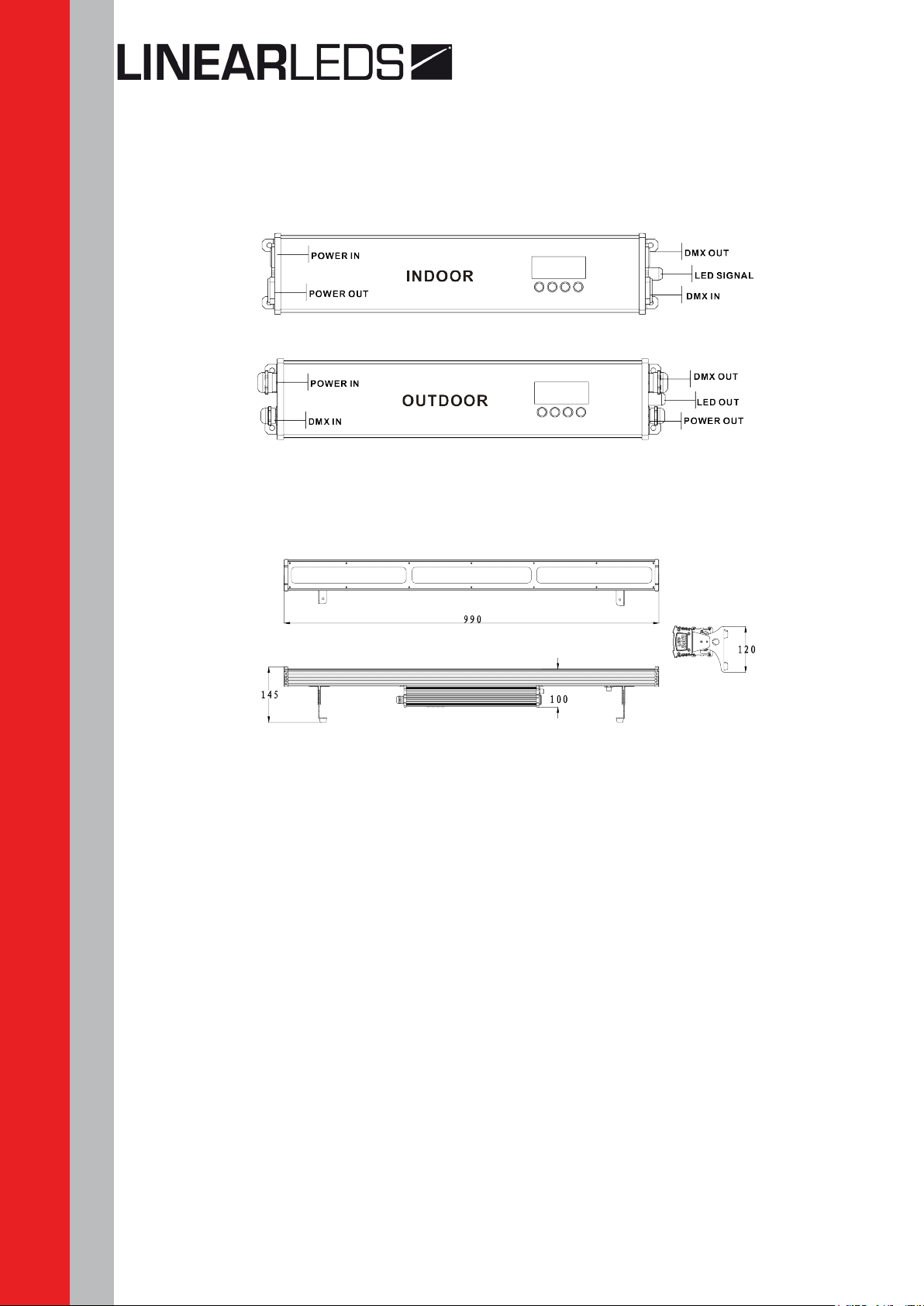
• Productsize:990X120X145mm
• Packagesize:1070X160X170mm
• N/W:5.7Kg
Features
• RGBWcolormixingwithorwithoutDMXcontroller
• Specialeect(minimum16psconegroup)
• 5 distinct dimming curves
• LEDdisplaywithpasswordprotection
• OperatingModes:DMX512connection/Master&Slave...
• DMXChannels:11/04/06/11/15/17/21/60channels
5
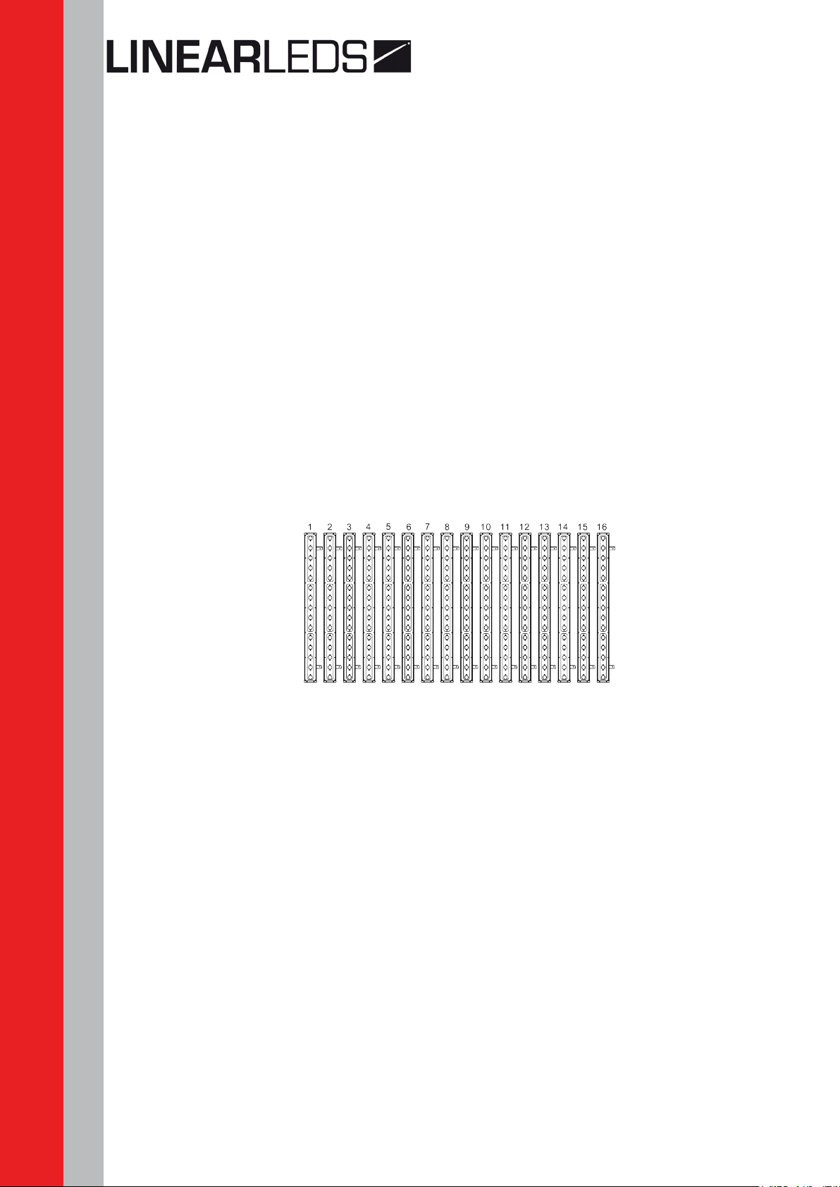
Product overview
Dimensions
3. SETUP
Installation requirement
Thisproductcanbeusedinavarietyofsituations,canhangandputontheground.
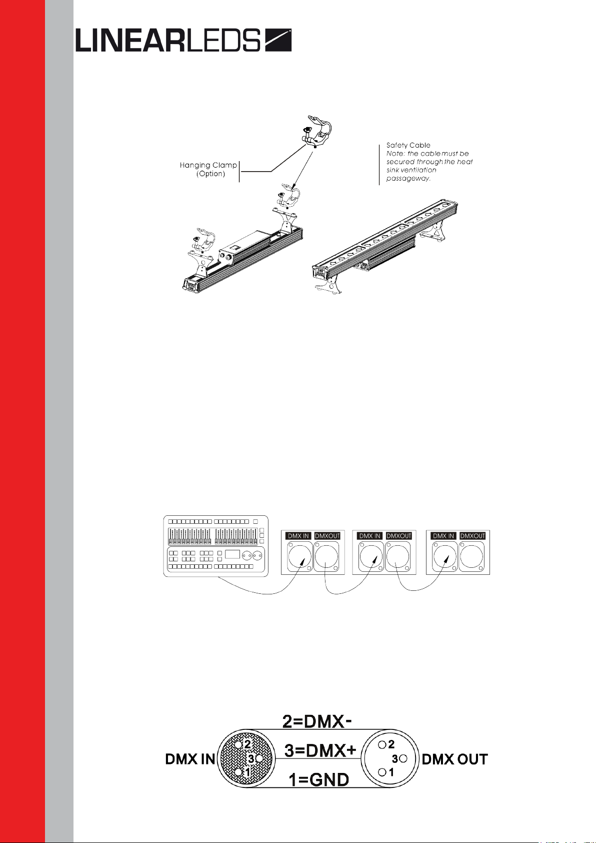
Ifhangingthextureforoverheaduse,thenpleasefollowthebelowsteps.
Please choose the suitable location to put or hang the light when installing it. You must use the
exclusiveclamphangerandscrewwhenhangingit,andmakesuretheweightofthelightis
within limits of the hanger.
Pleasemakesurewithoutanyammableobjectswithin0.5mwheninstallingthelight.
Theinstallationshouldbeoperatedbyprofessionalperson;anyirregularinstallationwillcause
thebodyinjuryorequipmentdamage.
Block access below the work area and use suitable and stable platform when installing or
servicingxture.
6
Connection of DMX signal wire
1. PleaseusethexturecontrollerwirespeciallywhenusetheDMX512controller.Connect
the(male)3pinconnectorsideoftheDMXcabletotheoutput(female)3pinconnectorof
therstxture.
2. Connecttheendofthecablecomingfromtherstxturewhichwillhavea(male)3pin
connectortotheinputconnectorofthenextxtureconsistingofa(female)3pinconnector.
Then,proceedtoconnectfromtheoutputasstatedabovetotheinputofthefollowingxture
and so on.
3. This product can be connected numerous lamps in series without the need for the signal
amplier;thesignalwillnotbeweakened.
3-PIN to 5-PIN conversion chart
Note:Ifyouuseacontrollerwitha5pinDMXoutputconnector,youwillneedtousea5pinto
3 pin adapter.

7
Conductor 3 Pin Female (output) 5 Pin Male (Input)
Ground/Shield Pin 1 Pin 1
Data(-)signal Pin2 Pin2
Data(+)signal Pin 3 Pin 3
Do not use Do not use
Do not use Do not use
4. OPERATING INSTRUCTIONS
Control panel functions
Button Function
Mode Exitsfromthecurrentmenuorfunction
Enter Enablesthecurrentlydisplayedmenuorsetsthecurrentlyselectedvalueintothe
selected function
Up Navigatesupwardsthroughthemenulistandincreasesthenumericvaluewhen
in a function
Down Navigatesdownwardsthroughthemenulistanddecreasesthenumericvalue
when in a function
Menu map
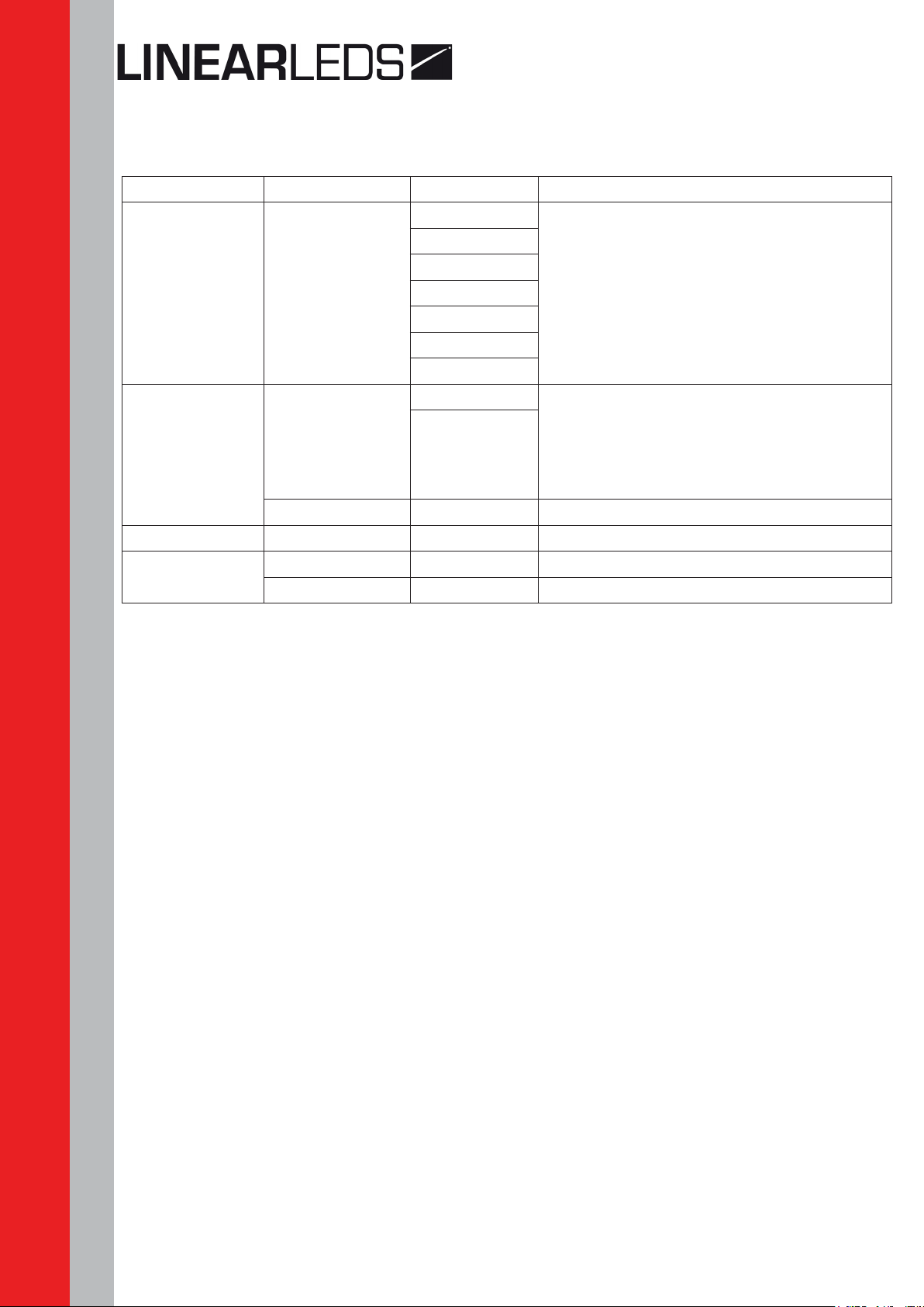
Main function Subfunction Selection Instruction
DMX d001 001~512 SetDMXstartaddress
Colo
R000
000~255
(0~100%)
Usercancombinered,green,blue
and white to generate a custom color
G000
b000
W000
5000 00~20 Selectstrobefrequency
AUTO
AT00 (01~50) SP00-20 Auto programs available
AP00 (01~50) SP00-20 Combine auto program
CP00 01~25 Combinecartooneects
SLAV SLA Slaves
8
Operating instructions
Enable password lock
(KEY) (ON) / (OFF){ENTER}
(ON)enablelock, (OFF)disablelock
Enable the password lock, control panel in the boot or go into standby automatically take
eect,thistimetooperatelampsneedtoenteryourpassword.{MODE,UP,MODE,DOWN,
MODE,UP,MODE,DOWN}{ENTER}
DMX512 controller mode
1. Setting DMX512 address
(DMX) (001--512)
AccesscontrolpanelfunctionbypressingMODEuntil(DMX) is displayed.
PressENTER,addorreducechannelsbypressingUP/DOWNbetween001and512.
PressMODEtoexit.
2. Setting channels
(PERS) (11CH/04CH /06CH /15 CH /17 CH /21 CH /60 CH)
AccesscontrolpanelfunctionbypressingMODEuntil(PERS) is displayed.
PressENTERbutton,selectDMXchannelbypressingUP/DOWN.
PressMODEtoexit.
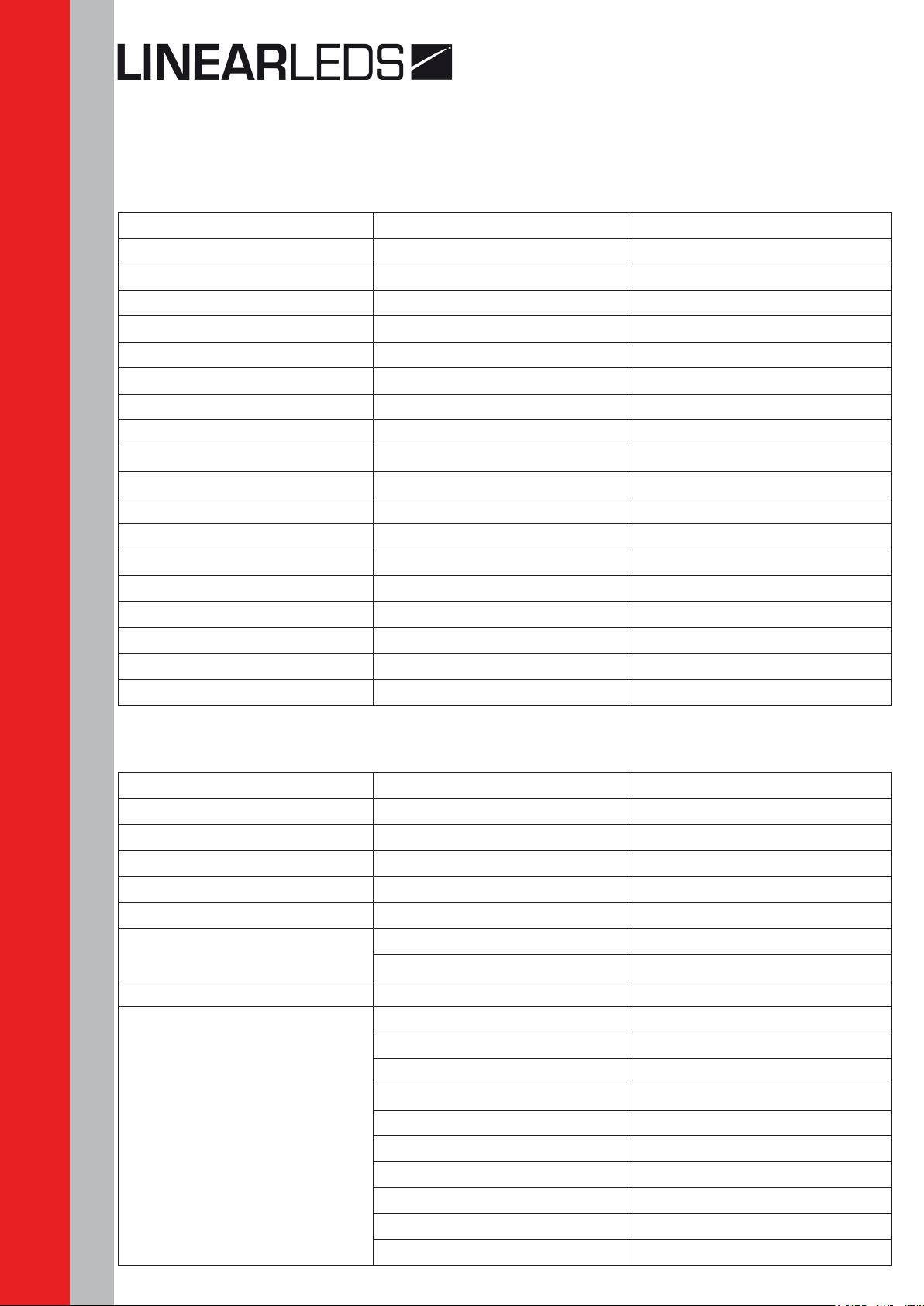
Main function Subfunction Selection Instruction
PERS
11CH
Select11/04/06/15/17/21/60channel
setting
04CH
06CH
15CH
17CH
21CH
60CH
SET d1M
OFF «O»meansselectlineardimming,or
choosedimmer1-4tocontrolthe
dimmingspeed,dimming1ofthefastest
dimmingcurves,4forthemostslowly
dimming curve
DIM1/2/3/4
VER Version number
KEY ON~OFF EnablesorDisablespasswordlockout
CoMP C.SUM 01~16 Amount set of combined lights
C.id 01~16 Numbersetofcombinedlights

9
DMX512 channel values
4 channels :
Channel Value Description
1 000~255 Red
2 000~255 Green
3 000~255 Blue
4 000~255 White
Channel6haspriorityoverchannels1-5.
When activating the auto programs, then it is possible to control the auto speed by using
channel 5.
15 channels
Channel Value Description
1.LED 000 ~015 Nofunction
2.LED 016~031 R
3.LED 032 ~047 G
4.LED 048~063 B
5.LED 064~079 R+G
6.LED 080~095 G+B
7.LED 096~111 R+B
8.LED 112 ~127 R+G+B
9.LED 128 ~143 W
10.LED 144~159 R+W
11.LED 160~175 G+W
12.LED 176~191 B+W
13.LED 192~207 R+G+W
14.LED 208 ~223 G+B+W
15.LED 224~239 R+B+W
240 ~255 R+G+B+W
6 channels
Channel Value Description
1 000~255 Red
2 000~255 Green
3 000~255 Blue
4 000~255 White
5000~255 Nofunction
006~255 Strobe / Auto speed
6000~005 Nofunction
006~255 AUTO(AT01~50)
10
17 channels
Channel Value Description
1.LED 000 ~015 Nofunction
2.LED 016~031 R
3.LED 032 ~047 G
4.LED 048~063 B
5.LED 064~079 R+G
6.LED 080~095 G+B
7.LED 096~111 R+B
8.LED 112 ~127 R+G+B
9.LED 128 ~143 W
10.LED 144~159 R+W
11.LED 160~175 G+W
12.LED 176~191 B+W
13.LED 192~207 R+G+W
14.LED 208 ~223 G+B+W
15.LED 224~239 R+B+W
240 ~255 R+G+B+W
16.Strobe 000 ~255 Strobe(0~20HZ)
17. Fade 000 ~255 Dimmerspeed(fasttoslow)
11 channels
Channel Value Description
1. Dimming 000~255 0-100%
2.Red 000~255 0-100%
3.Green 000~255 0-100%
4. Blue 000~255 0-100%
5.White 000~255 0-100%
6.Macrocolorcontrol 000~009 Nofunction
010~255 Macro color control
7. Strobe 000~255 Strobe(00~20Hz)
8. Module selection
000~004 #1=ON,#2=ON,#3=ON,
005~034 #1=ON
035~064 #2=ON
065~094 #3=ON
095~124 #1=ON,#2=ON
125~154 #1=ON,#3=ON
155~184 #2=ON,#3=ON
185~214 #1=ON,#2=ON,#3=ON,
215~244 #1=OFF,#2=OFF,#3=OFF,
245~255 Convertto11CH-2
11
Master dimmer
Channel 1 controls the intensity of the currently projected color when the slider is at the highest
position(255),thentheintensityoftheoutputisatthemaximum.
Red, green, blue and white color selection
Channels2,3,4and5controltheintensityratioofeachoftheRed,Green,Blue&WhiteLEDs.
1,2,3,4and5channelscanbeusedincombination.
Color macros
Channel6selectstherequiredcolormacro.
Channel6haspriorityoverchannels2,3,4&5.
Channel 1 is used to control the intensity of the current color macro.
Strobe
Channel7controlsthestrobeofchannels1through6.
Channel7haspriorityoverchannels2,3,4&5.
Speedofthestrobeisadjustablefrom0to20Hz.
Module selection
Channel8providesindividualcontrolofthethreeLEDmodulesineachxture.
245~255switchtothe11CH-2mode.
Auto programs
Chanel9selectsthepresetautoprograms1~50.
Whenactivatingtheautoprograms,thenitispossibletocontrol.
the auto speed by using channel 10.
Channel9haspriorityoverchannels2-8.
Dimmer speed
Channel 11 is for selecting the dimmer mode and dimmer speed.
Whenchannel11isnotactivated,thenRGBWandmasterdimmerarelinear.
Thedimmermodes1,2,3and4aredierentspeedsofthenonlineardimmingcurves.
Channel Value Description
8. Module selection 245~255 Convertto11CH-2
9.Auto 000~005 Nofunction
006~025 Auto(AT01~50)
10 000~255 Auto speed
11 000~255 Dimmer speed

12
21 channels
Channel Value Description
1.LED1 000~015 Nofunction
2.LED2 016~031 R
3.LED3 032~047 G
4.LED4 048~063 B
5.LED5 064~079 R+G
6.LED6 080~095 G+B
7.LED7 096~111 R+B
8.LED8 112~127 R+G+B
9.LED9 128~143 W
10.LED10 144~159 R+W
11.LED11 160~175 G+W
12.LED12 176~191 B+W
13.LED13 192~207 R+G+W
14.LED14 208~223 G+B+W
15.LED15 224~239 R+B+W
240~255 R+G+B+W
16.Module1 000~005 Nofunction
17. Module 2
18. Module 3 006~255 Strobe(0~20HZ)
19.Module1fade 000~255 Dimmer speed
20. Module 2 fade 000~255 Dimmer speed
21. Module 3 fade 000~255 Dimmer speed
Attention:Module1iscomposedof1-5LED.
Module2iscomposedof6-10LED.
Module3iscomposedof11-15LED.
60 channels
Channel Value Description
1.LED1 000~255 Red(0~100%)
2.LED1 000~255 Green(0~100%)
3.LED1 000~255 Blue(0~100%)
4.LED1 000~255 White(0~100%)
5.LED2 000~255 Red(0~100%)
... ? ...
57.LED15 000~255 Red(0~100%)
58.LED15 000~255 Green(0~100%)
59.LED15 000~255 Blue(0~100%)
60.LED15 000~255 White(0~100%)
13
Master / Slave control mode
1. Setting master machine
AccesscontrolpanelfunctionbypressingMODEuntil(AUTO) is displayed.
PressENTER,select(AT00)/(AP00)/(CP00)bypressingUP/DOWNbuttons.
PressENTERandthenpressMODEtoexit.
You can choose (AT00)pre-setprograms,therangeis(o1--50).
Or you can choose (AP00)customprograms,therangeis(o1--50).
2. Setting slave machine
AccesscontrolpanelfunctionbypressingMODEuntil(SLAV)is displayed.
PressENTER.
Group working
1. Amount set of combined lights
AccesscontrolpanelfunctionbypressingMODEuntil(COMP)isdisplayed.
PressENTER,select(C.SUM)bypressingUP/DOWNbuttons.
PressENTER,amountsetofcombinedlights,bypressingUP/DOWNbetween01and16.
PressMODEtoexit.
2. Number set of combined lights
AccesscontrolpanelfunctionbypressingMODEuntil(COMP)isdisplayed.
PressENTER,select(C.ID)bypressingUP/DOWNbuttons.
PressENTER,Amountsetofcombinedlights,bypressingUP/DOWNbetween01and16.
PressMODEtoexit.
Attention : The number of the light could not bigger than the amount of the combined lights.
3. Setting master machine
AccesscontrolpanelfunctionbypressingMODEuntil(AUTO)isdisplayed.
PressENTER,select(AT),(AP)or(CP)bypressingUP/DOWNbuttons.

14
Channel Value Description
1. Module 1
2. Module 2
3. Module 3
000 ~ 015 Nofunction
016~031 R
032 ~ 047 G
048~063 B
064~079 R+G
080~095 G+B
096~111 R+B
112 ~ 127 R+G+B
128 ~ 143 W
144~159 R+W
160~175 G+W
176~191 B+W
192~207 R+G+W
208 ~ 223 G+B+W
224~239 R+B+W
240 ~ 255 R+G+B+W
4000 ~ 005 Nofunction
006~255 Strobe020HZ
5
000 ~ 005 Nofunction
006~255 Combineautoprogram(AP
1~50)
6
000~009 Nofunction
010 ~ 255 Combinecartooneects(CP
1~25)
7 000 ~ 255 Nofunction
8. Mode selection 000 ~ 244 Convertto11CH-1
245 ~ 255 Convertto11CH-2
9000 ~ 005 Nofunction
006~255 AUTO(AT1~50)
10 000 ~ 255 CH5/6/9autospeed
11 000 ~ 255 Dimmer speed
4. Setting slave machine
AccesscontrolpanelfunctionbypressingMODEuntil(SLAV)is displayed.
PressENTER.
Group working (DMX512 mode)
11CH-2
15
Auto programs
Chanel5selectsthepresetcombineautoprogram(AP1~50)
Chanel6selectsthepresetcombinecartooneects(CP1~25)
Chanel9selectsthepresetautoprogram(AT1~50)
When activating the auto programs, then it is possible to control the auto speed by using
channels 10.
Channel9haspriorityoverchannels2-8.
Channel5haspriorityoverchannels2-6.
Channel6haspriorityoverchannels2-4.
5. APPENDIX
Service maintenance guide
Symptom(s) Possible Solution(s)
1ormoreLED’s
are not illuminating
Cleanthextureregularlytoavoidanysuchfailure.Thisxtureis
convectioncooled,whichmeansthatifthesurfaceiskeptcleanand
freeofdebris,thenpropercoolingwillbeallowedtooccur.
AnLEDmayhavefailed,resultinginanopencircuit.Inthisevent,all
ofthered,green,orblueinasinglemodulewillnolongerilluminate.
ThisdoesnotmeanthatalloftheLEDshavefailed,butthecircuitis
wired in series.
AnLEDmayhavefailed,resultinginashortcircuit.Inthisevent,
onlythesingleLEDwhichhasfailedwillnolongerfunction.This
doesnotmeanthatalloftheLEDshavefailed,butthecircuitis
wired in series.
Note:IntheeventofLEDfailure,areplacementLEDPCBassembly
may be purchased directly from our company.
Breaker/Fusekeeps
blowing
Checktotalloadplacedontheelectricalcircuit.
Checkforashortintheelectricalwiring:internaland/orexternal.
Device has no power
Checkforpoweronmains.
Note:Intheeventofautoswitchingtransformerfailure,theunitcan
besentinforrepair;however,areplacementpartcanbeordered
directly from our company.
Fixture is not
respondingtoDMX
Checkcontrolpanelsettingsforcorrectaddressing.
CheckDMXcables.
Checkpolarityswitchsettingsonthecontroller.
Checkcableconnections.
Call service technician.
Note:IntheeventofdisplayPCBfailure,areplacementPCBcan
be ordered directly from our company.
16
Symptom(s) Possible Solution(s)
Loss of signal
UseonlyDMXcables.
Install terminator.
Note:KeepDMXcablesseparatedfrompowercablesorblack
lights.
COLOR-CON
controller does not
function,ordoesnot
function properly
Makesureconnectorisrmlyconnectedtodevice.
Thisxturemustbeinthecorrectmodeinordertoproperlyrespond
totheCOLOR-CONcontroller.Thecorrectmodeis“DMX”inthe
onboard control panel.
Stand alone
operation
Thisxturehasbuilt-in,automaticprogramsthatmaybetriggered
from the onboard control board.
The display is only
showing : ####
Thepasswordlockouthasbeenenabled.Youcanusethepassword:
{MODEUPMODEDOWNMODEUPMODEDOWN}

Linear Technologie • 11 rue du Puits Rochefort • 42 100 Saint-Etienne
Tél: +33 (0)4 77 81 49 49 • Fax: +33 (0)4 77 81 49 40 • www.lineartech.fr
Table of contents


