Linear Security LSE.CD700VAR User manual

Linear Technologie • 11 rue du Puits Rochefort • 42 100 Saint-Etienne
Tél: +33 (0)4 77 81 49 49 • Fax: +33 (0)4 77 81 49 40 • www.lineartech.fr V.2017
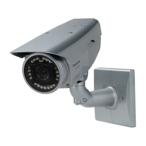
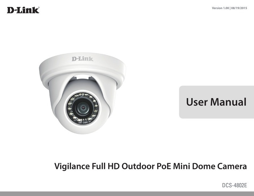
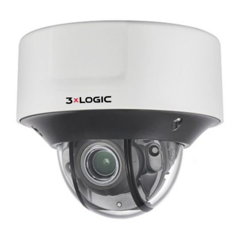
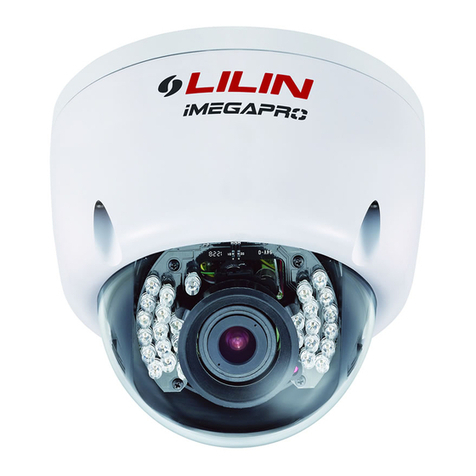
DOME CAMERA 700 TVL LSE.CD700VAR
Operation manual

2
TABLE OF CONTENTS
1. Specications
2. Dimensions
3. Pack content
4. Installation
5. Camera adjustment
Page 4
Page 4
Page 5
Page 5
Page 7

3
The lightning with an arrowhead symbol, within an equilateral triangle is
intended to alert the users to the presence of uninsulated “dangerous voltage”
within the product’s enclosure that may be sucient magnitude to constitute a
risk of electric shock to persons.
TO REDUCE THE RISK OF ELECTRIC SHOCK
DO NOT REMOVE COVER (OR BACK)
NO USER SERVICEABLE PARTS INSIDE.
REFER SERVICING TO QUALIFIED
SERVICE PERSONNEL.
The exclamation point with an equilateral triangle is intended to alert the user to
the presence of important operating and maintenance (servicing) instructions
in the literature accompanying the appliance.
This equipment has been tested and found to comply with limits for a Class A digital device,
pursuant to part 15 of the FCC Rules. These limits are designed to provide reasonable
protection against harmful interference when the equipment is operated in a commercial
environment. This equipment generates, uses, and can radiate radio frequency energy,
if not installed and used in accordance with the instruction manual, may cause harmful
interference to radio communications.
Operation of this equipment in a residential area is likely to cause harmful interference in
which case the user will be required to correct the interference at his own expense.
Changes or modifcations not expressly approved by the manufacturer could void the user’s
authority to operate the equipment. To prevent electric shock and risk of fre hazards : Do not
use power sources other than that specifed.
This installation should be made by a qualifed service person and should conform to all local
codes.
* Operation is subject to two conditions :
1.This device may not cause harmful interference,
2. This device must accept any interference received, including interference that may cause
undesired operation.

4
1. SPECIFICATIONS
2. DIMENSIONS
Sensor 8.5mm (1/3’’) SONY CCD
Objectif 2.8-12mm Varifocal Day/Night Lens
Technology Advanced Digital Noise Reduction (DNR)
Shadow Reduction (ATR)
Menu OSD Menu Control
Hiding Privacy Masking / Motion Detection
Output Video (BNC)
Power supply 12V DC or 24V AC (option)
LEDS 21 LEDs IR 850nm
Power supply 12V DC / 12V DC et 24V AC
ConsoPower consumption 3W max.
Scanning system 2:1 i nterlace
Scanning frequency 15.734kHz(H), 59.95Hz(V)
Min. illumination 0 Lux IR LED On
Video output 1.0 Vp-p (75Ohm, composite)
S/N ratio more than 50dB (AGC OFF)
Video output BNC Connector (2nd video RCA)
Lens mount Fixed mount
Lens 2.8 - 12mm varifocal
Operating temperature De -10°à 50°C
Operating humidity 0 - 99% (non-condensing)

5
3. PACK CONTENT
3 screws 70mm 3 screws 30mm 3 plug 04mm
Camera in housing..................................... 1
Camera Locking screw (PM3 Type)........... 1
Instruction guide (This Document)............. 1
Surface Mounting Template....................... 1
RCA - BNC test cable.............................. 1
PMounting screw pack............................ 1
Star Shape Dome Cover Tamper key...... 1
4. INSTALLATION
a) Remove the three tamper screws using the star key provided.
b) Install Method 1 : use included mounting template to mark
and pre-drill the required holes. Use included 2.8” screws to
mount the camera directly to the mounting surface. Proceed to
step 4
Install Method 2 : remove the camera base by unscrewing the
base locking screw (indicated with a padlock marking) and turn
camera module approx. 5 degrees counter-clockwise to detach
camera base from the camera module. Proceed to step 3.
a) If you plan on installing onto a junction box, attach provided mounting plate rst to the
junction box and then attach camera base to the mounting plate.
b) Reinsert camera module into camera base by ligning up the arrow notches, and turning
camera module clockwise to lock into place.
c) Reinstall base locking screw as indicated by padlock mark to secure camera base to
camera module.

6
a ) Remove camera cover by squeezing the back and front of
the cover as indicated by the “PRESS” indicators at the same
time and lifting it up and away from the lens.
b ) Insert the included video test cable into the RCA jack and
connect to test monitor to set up camera. (see page 8)
c ) Adjust camera viewing angle and secure into place by
tightening thumb screw using a at head screwdriver. Make lens
and OSD adjustments as required.
a ) Re-attach the camera cover, using the locking nut as a guide,
until it snaps into place.
b ) Use the Hex key to tighten the tamper screws to create a
proper weatherproof seal.

7
5. CAMERA ADJUSTMENT

8
OSD MENU control
Press down on the function joystick to access the setup menu.
SETUP MENU
Select a function by moving the joystick up and down and move left or right to change setting
value and press joystick to conrm selection.
If a menu option features a , a sub menu is available which can be accessed by pressing
down on the joystick.
Select ‘NEXT ’ to view remainder of the OSD setup menu Once nished updating settings,
highlight ‘EXIT’ and press down on the joystick to exit setup menu.
To retain the changed settings after a power on/o of the camera you need to select SAVE
ALL option on the menu.
LENS
LANGUAGE
TYPE
MODE
• AUTO: The mechanical iris is controlled automatically
• CLOSE: The mechanical iris is set to the closed position
• OPEN: The mechanical iris is set to the open position
Default setting is Auto
SPEED 000-255
Sets the convergence speed of the mechanical iris. Default setting is 80
SHUTTER/AGC
Shutter has two options : AUTO or MANUAL.

9
AUTO SETUP HIGH LUMINANCE
MODE : SHUT
BRIGHTNESS: 000 - 255
Default setting is 32
MODE : SHUT (FERMé) + AGC
SHUTTER : 1/60 1/120 1/250 1/500 1/1000 1/2000
1/4000 1/10000.
Shutter speed in fractions of a second. Default setting is 1/60
AGC : 6.00 / 12.00 / 18.00 / 24.00 / 30.00 / 36.00 / 42.00 /
44.80 - AGC value in [dB] Default setting is 6.00
WHITE BAL
White Balance can be set to following :
ATW / PUSH / USER1 / USER2 / ANTI CR / MANUEL / PUSH LOCK
SPEED : 000 - 255 Default setting is 239
DELAY CNT : 000 - 255 Default setting is 16
ATW FRAME : x0.50 / x1.00 / x1.50 / x2.00 Default setting is x1.00
ENVIRONNEMENT : INDOOR / OUTDOOR. Default setting is
OUTDOOR
USER 1 (utilisateur 1)
User dened gain adjustment on B and R
USER 2 (utilisateur 2)
B-GAIN 000-255 B Gain adjustment for WB
R-GAIN 000-255 R Gain adjustment for WB
User dened gain adjustment on B and R

10
ANTI CR
MANUEL ATW
Picture and display control settings
MIRROIR : ON / OFF Horizontally ip the display output
BRIGHTNESS : 000 - 255 Screen brightness
CONTRAST : 000 - 255 Screen contrast
SHARPNESS : 000 - 255 Screen sharpness
HUE : 000 - 255 Adjust the hue
GAIN : 000 - 255 Adjust the gain
Digital Noise Reduction (NR)
This function reduces the background noise in a low luminance environment.
NR MODE : Y/C / OFF / Y / C Noise reduction Filter mode
Y LEVEL : 000 - 015 Adjustment of the Y lter strength, Default
setting is 004.
C LEVEL : 000 - 015 Adjustment of the C lter strength. Default
setting is 004
NEXT
From the main setup menu select NEXT to enter second
page of main setup menu.
LEVEL (niveau)
0 - 255
Species the R and B gain values for manual WB.
Default setting is 58

11
BACKLIGHT
OFF / BLC / HLC
- OFF : Backlight compensation OFF
- BLC : Backlight compensation ON
- HLC : High light compensation ON
SHADOW REDUCTION (ATR)
This function compensates for darker areas surrounding the object to provide naturally sharp
picture and improves contrast in bright/dark areas.
LUMINANCE : Sets the extent of the luminance compression MID /
HIGH / LOW (MOYENNE / HAUTE / BASSE)
CONTRASTE : MID / MIDHIGH / HIGH / LOW / MIDLOW)
PRIVACY
Hide an area so that it is not displayed on the monitor.
MOTION DET CAMERA ID
SYNC (synchronisation)
INT (Internal) / LL (Line Lock)
And LL setting for camera model when connected to a AC supply. Adjust the phase in the
vertical direction when the line lock mode is available.
CAMERA RESET : This will reset all settings for all menus to manufacturer defaults. This
allow you to return to shipped settings from the manufacturer.
EXIT / SAVE ALL
EXIT : Exit OSD menu
SAVE ALL : Saves the settings to camera

Linear Technologie • 11 rue du Puits Rochefort • 42 100 Saint-Etienne
Tél: +33 (0)4 77 81 49 49 • Fax: +33 (0)4 77 81 49 40 • www.lineartech.fr
Table of contents
