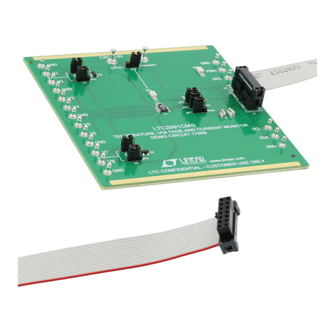
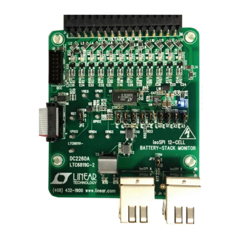
Linear Technology LTC6801 Quick setup guide

1
dc1469bf
DEMO MANUAL DC1469B
Description
LTC6801
Multicell Li-Ion Battery
Monitor
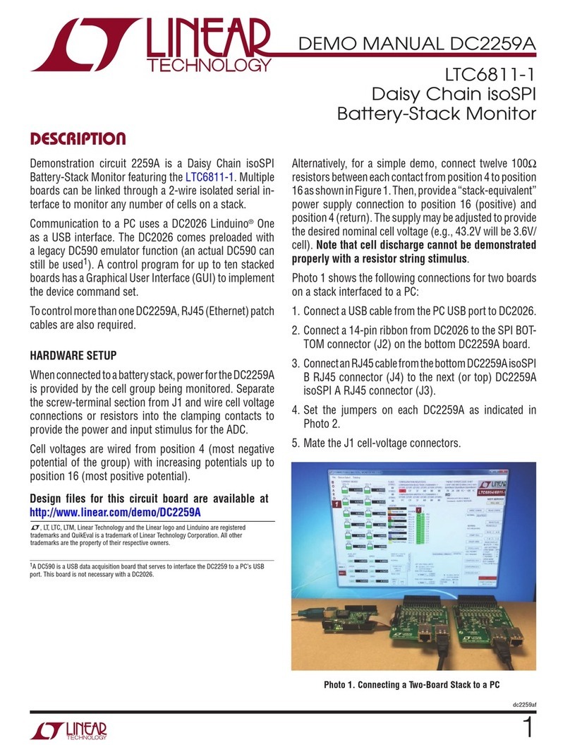
Demonstration circuit 1469B is a multicell Li-Ion battery
monitorfeaturingtheLT C
®
6801.Thiscircuitautonomously
detects individual over- and undervoltage conditions
on up to 12 series connected lithium-ion cells and two
temperature limits using suitable sensors. Pin-strapping
establishes the cell count to monitor, the threshold for
OV, threshold for UV, alarm hysteresis, and measurement
interval. A square wave is used to excite the alarm circuit,
and a returned signal duplicates this if no alarms are pres-
ent, but returns a static signal when a fault condition is
present. The circuit also provides a means of cascading
L, LT, LTC, LTM, Linear Technology and the Linear logo are registered trademarks of Linear
Technology Corporation. All other trademarks are the property of their respective owners.
performance summary
numerous monitors together so that very large series con-
nected arrays of cells can be monitored simultaneously.
Additional support features are provided on the demo
circuit, including a digital excitation source and an alarm
indicator LED, so that standalone evaluations can be per-
formed. Jumpers are provided to provide for local signal
loop back and to activate the desired support circuits.
The following table indicates the performance and control
ranges of the LTC6801.
Design files for this circuit board are available at
http://www.linear.com/demo/DC1469B
Specifications are at TA= 25°C
SYMBOL PARAMETER CONDITIONS MIN TYP MAX UNITS
VIN Total Input Supply Range Total Potential of Series-Connected Cells 10 60 V
IQS Supply Current, Idle Current into V+Pin When Idle 30 µA
IMSupply Current, Measuring 15ms (Continuous)
130ms
500ms
700
200
90
µA
µA
µA
N Number of Cells Monitored 9 Strappable Choices 4 12 Cells
VUV Individual Cell Undervoltage Threshold 9 Strappable Choices 0.77 2.88 V
VOV Individual Cell Overvoltage Threshold 9 Strappable Choices 3.74 4.51 V
HYSUV Individual Cell Undervoltage Alarm Hysteresis 3 Strappable Choices 0 500 mV
HYSOV Individual Cell Overvoltage Alarm Hysteresis 0 200 mV
TCYCLE Measurement Cycle Time 3 Strappable Choices 15 500 ms
VERR Measurement Error –1 1 %
TEMPOP Operational Temperature Range –40 25 85 °C
TEMPLIM Temperature Alarm Limits (Nominal) Set by Onboard Thermistors –20 60 °C
FIN Alarm Enable Input Frequency Digital Square Wave 1 10 50 kHz

2
dc1469bf
DEMO MANUAL DC1469B
operating principles
The LTC6801 accepts a differential logic enable input EIN
and duplicates it on EOUT to drive a cascaded LTC6801
EIN port. A differential logic sense input SIN receives a
signal the same as EOUT (but usually from a cascaded
LTC6801) and performs a phase detection function. When
thephase detection finds a good correlation AND noalarms
are detected, the EIN signal propagates to the SOUT of the
LTC6801 and can drive the SIN port of an LTC6801 lower
in the cascade. For a single LTC6801, the EOUT signals are
simply looped back to the SIN port and the SOUT signal is
used to determine the alarm state. Logic signals passing
between cascaded LTC6802 devices are AC-coupled to
provide dielectric isolation. On the DC1469B, the coupling
is performed by 500V rated capacitors.
DC1469B provides an onboard 10kHz oscillator that can
be jumper configured to activate and drive the local EIN.
In a cascaded arrangement of demo circuits, only the
bottom-of-stack unit would be so configured, and only
in the event that an external stimulus wasn’t available.
The oscillator must be disabled to demonstrate minimum
power (i.e. in the idle condition).
An LED indicator circuit is also provided to allow visual
indication of the alarm condition. If activated by the jumper
configuration,the green indication shows thatall measure-
ments are within normal limits. Since the LED consumes
a few milliamperes, the feature should be disabled to
demonstrate lowest battery drain.
ConnectorsareprovidedtointerconnectmultipleDC1469B
boards in cascade. Ribbon cables perform the daisy chain,
and jumpers allow configuring the cascade connection as
a loop back for the top-of-stack unit.

3
dc1469bf
DEMO MANUAL DC1469B
Quick start proceDure
Demonstration circuit 1469B is easy to set up to evalu-
ate the performance of the LTC6801. Refer to Figure 1
for proper measurement equipment setup and follow the
procedure below:
1. Place jumpers in the following positions:
JP1 to JP5 GND position (horizontally)
JP6, JP7 VREG position (horizontally)
JP8 GND position (horizontally)
JP9 Both shunts in LOOP position (horizontally)
JP10 SE position
JP11 ON position
JP12 Both shunts in ON position (vertically)
2. J1 is a two-piece connector. The removable section
has the screw-clamp array, and may have been shipped
either mated, loose, or parked on the pass-through
fingers at the right edge of the board. This connector
allows for quick assembly of a wire harness to a cell
array (or cell array simulator). If such harnessing or
cell simulator has already been set up to work with
other Linear battery monitor demo circuits (DC1393B
for example), the movable part may be clamped to the
DC1469B battery pass-through fingers to form a simple
extender assembly. The harness connects to taps in
the cell array, supporting 4 to 12 cells of monitoring.
For cell counts less than 12, the topmost contact must
share a connection with the uppermost cell potential
of the group to properly power the LTC6801, and JP6
and JP7 reconfigured accordingly.
3. Turn on the power at the cell simulator, and adjust to
about 3V per cell (i.e. 36V for 12 cells).
NOTE: Make sure that the total input potential does not
exceed 60V. Individual cell potentials must not exceed
6V or protective Zener diodes will conduct.
4. The LED should illuminate, indicating that the monitor
is detecting nominal operating conditions. SOUT will
be a square wave like that furnished to EIN (SOUT/ is
the complement of SOUT).
5. Vary the cell simulator supply to see the alarm condi-
tion occur (LED dark and SOUT low). For the settings
given, thresholds are at about 9V and 45V for the total
12-cell potential. Refer to the data sheet and schematic
diagram (see Figure 2) for specific configurations of
other thresholds and parameters that may be of interest.
6. If multiple DC1469B assemblies are being evaluated,
they may be cascaded by attaching a ribbon from J3
to the J2 of another board. Board(s) with a ribbon at-
tached to J3 must have JP9 jumpers relocated to the
LINK position (horizontally). Board(s) with a ribbon
attached to J2 must have JP10 set to DIFF and JP12
jumpers in the OFF position (vertically) or removed.
7. To demonstrate standby power conditions, place both
JP12 jumpers to the OFF position (vertically) to inhibit
the enable clock. Supply current can be calculated
by the voltage drop on R13 (100Ω). Supply current
is somewhat dependant on the jumper configuration
strapping.

4
dc1469bf
DEMO MANUAL DC1469B
Quick start proceDure
Figure 1. Proper Evaluation Equipment Setup

5
dc1469bf
DEMO MANUAL DC1469B
Information furnished by Linear Technology Corporation is believed to be accurate and reliable.
However, no responsibility is assumed for its use. Linear Technology Corporation makes no representa-
tion that the interconnection of its circuits as described herein will not infringe on existing patent rights.
schematic Diagram

6
dc1469bf
DEMO MANUAL DC1469B
Linear Technology Corporation
1630 McCarthy Blvd., Milpitas, CA 95035-7417
(408) 432-1900 ●FAX: (408) 434-0507 ●www.linear.com
LINEAR TECHNOLOGY CORPORATION 2015
LT 0315 • PRINTED IN USA
DEMONSTRATION BOARD IMPORTANT NOTICE
Linear Technology Corporation (LT C ) provides the enclosed product(s) under the following AS IS conditions:
This demonstration board (DEMO BOARD) kit being sold or provided by Linear Technology is intended for use for ENGINEERING DEVELOPMENT
OR EVALUATION PURPOSES ONLY and is not provided by LT C for commercial use. As such, the DEMO BOARD herein may not be complete
in terms of required design-, marketing-, and/or manufacturing-related protective considerations, including but not limited to product safety
measures typically found in finished commercial goods. As a prototype, this product does not fall within the scope of the European Union
directive on electromagnetic compatibility and therefore may or may not meet the technical requirements of the directive, or other regulations.
If this evaluation kit does not meet the specifications recited in the DEMO BOARD manual the kit may be returned within 30 days from the date
of delivery for a full refund. THE FOREGOING WARRANTY IS THE EXCLUSIVE WARRANTY MADE BY THE SELLER TO BUYER AND IS IN LIEU
OF ALL OTHER WARRANTIES, EXPRESSED, IMPLIED, OR STATUTORY, INCLUDING ANY WARRANTY OF MERCHANTABILITY OR FITNESS
FOR ANY PARTICULAR PURPOSE. EXCEPT TO THE EXTENT OF THIS INDEMNITY, NEITHER PARTY SHALL BE LIABLE TO THE OTHER FOR
ANY INDIRECT, SPECIAL, INCIDENTAL, OR CONSEQUENTIAL DAMAGES.
The user assumes all responsibility and liability for proper and safe handling of the goods. Further, the user releases LT C from all claims
arising from the handling or use of the goods. Due to the open construction of the product, it is the user’s responsibility to take any and all
appropriate precautions with regard to electrostatic discharge. Also be aware that the products herein may not be regulatory compliant or
agency certified (FCC, UL, CE, etc.).
No License is granted under any patent right or other intellectual property whatsoever. LT C assumes no liability for applications assistance,
customer product design, software performance, or infringement of patents or any other intellectual property rights of any kind.
LT C currently services a variety of customers for products around the world, and therefore this transaction is not exclusive.
Please read the DEMO BOARD manual prior to handling the product. Persons handling this product must have electronics training and
observe good laboratory practice standards. Common sense is encouraged.
This notice contains important safety information about temperatures and voltages. For further safety concerns, please contact a LT C applica-
tion engineer.
Mailing Address:
Linear Technology
1630 McCarthy Blvd.
Milpitas, CA 95035
Copyright © 2004, Linear Technology Corporation
Table of contents
Other Linear Technology Monitor manuals
