Linear Technology LTC4245CUHF User manual


Table of contents
Other Linear Technology Motherboard manuals
Linear Technology
Linear Technology DC1763A Quick setup guide
Linear Technology
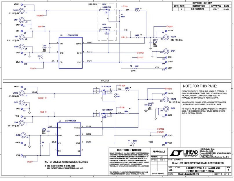
Linear Technology 1635A Administrator Guide
Linear Technology
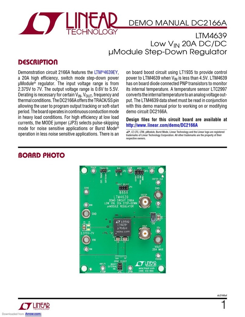
Linear Technology DC2166A Quick setup guide
Linear Technology
Linear Technology DC1705C Quick setup guide
Linear Technology
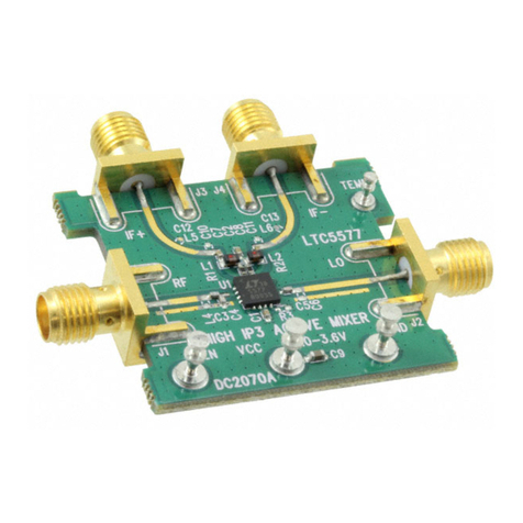
Linear Technology DC2070A Quick setup guide
Linear Technology
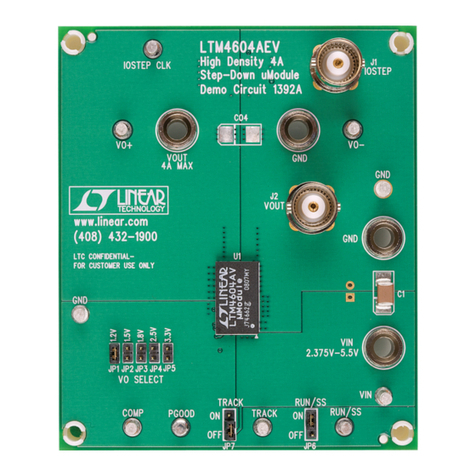
Linear Technology DC1392A Quick setup guide
Linear Technology
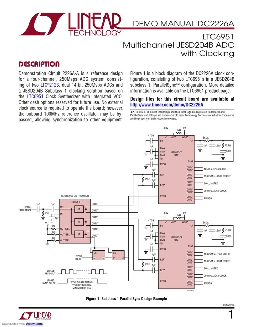
Linear Technology DC2226A Quick setup guide
Linear Technology
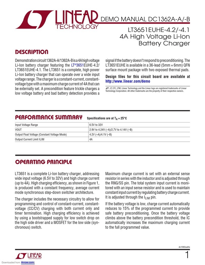
Linear Technology DC1362A-A Quick setup guide
Linear Technology
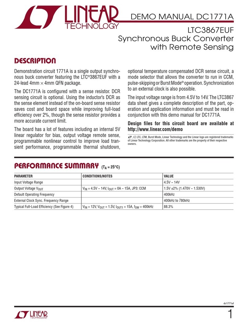
Linear Technology DC1771A Quick setup guide
Linear Technology
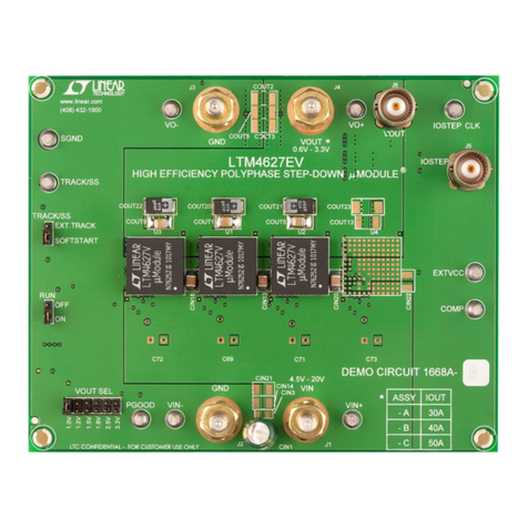
Linear Technology DC1668A-B Quick setup guide
Linear Technology
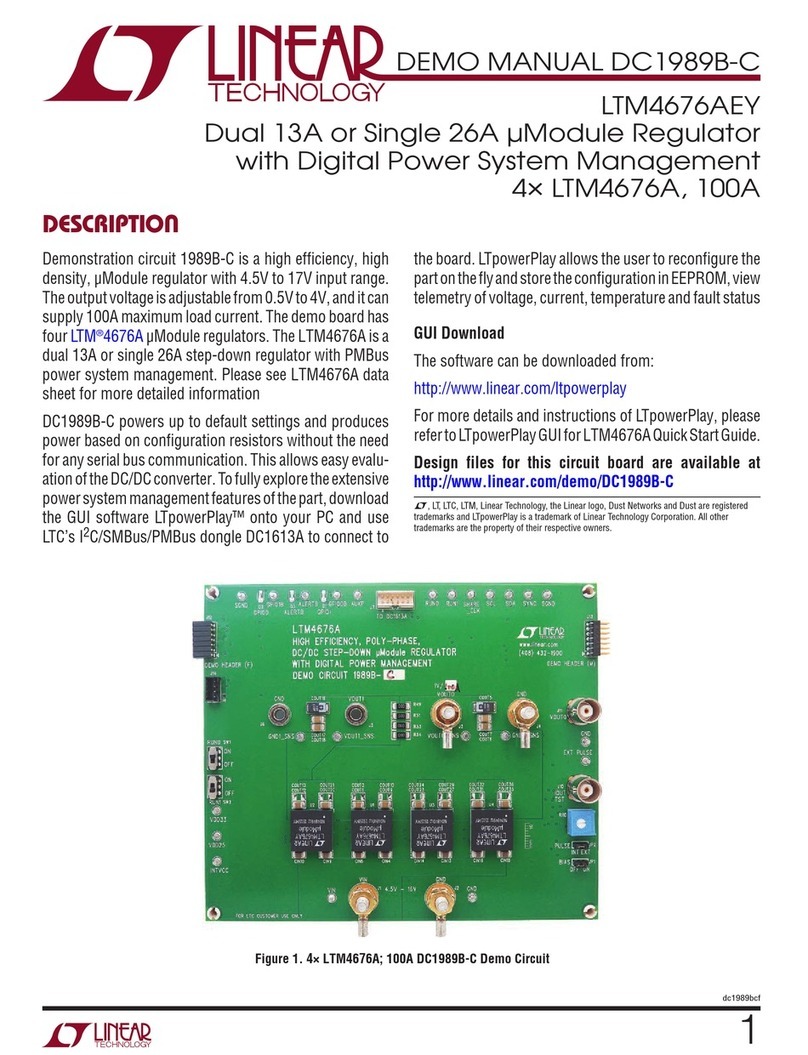
Linear Technology DC1989B-C Quick setup guide
Linear Technology
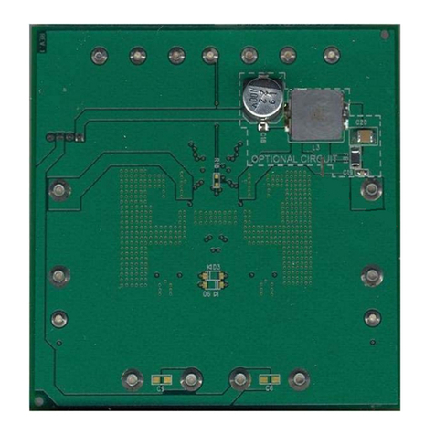
Linear Technology DC1537A Quick setup guide
Linear Technology
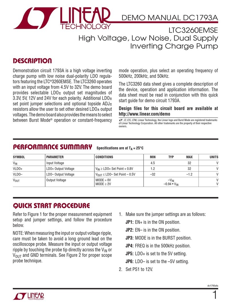
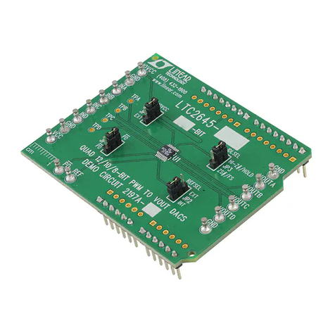
Linear Technology DC1793A Quick setup guide
Linear Technology
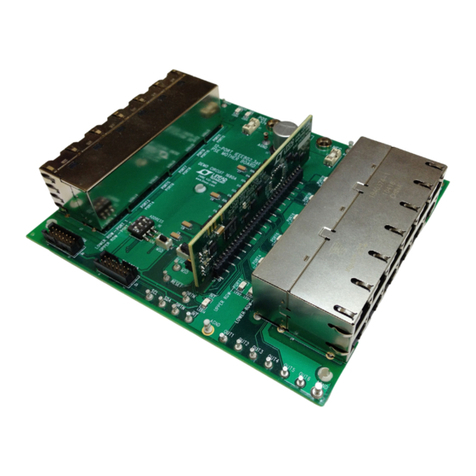
Linear Technology DC2197A Quick setup guide
Linear Technology
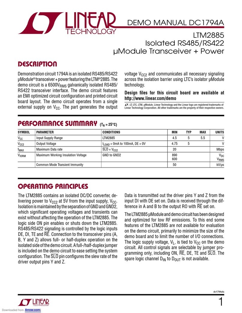
Linear Technology DC1682B Quick setup guide
Linear Technology
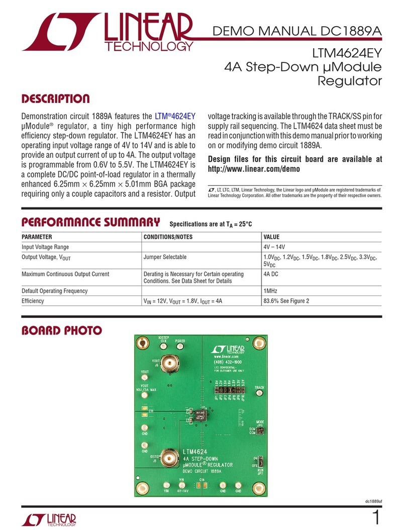
Linear Technology DC1794A Quick setup guide
Linear Technology
Linear Technology DC1889A Quick setup guide
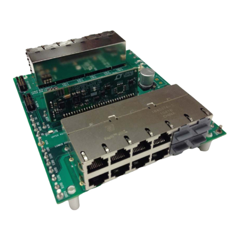
Linear Technology
Linear Technology DC1842A Quick setup guide
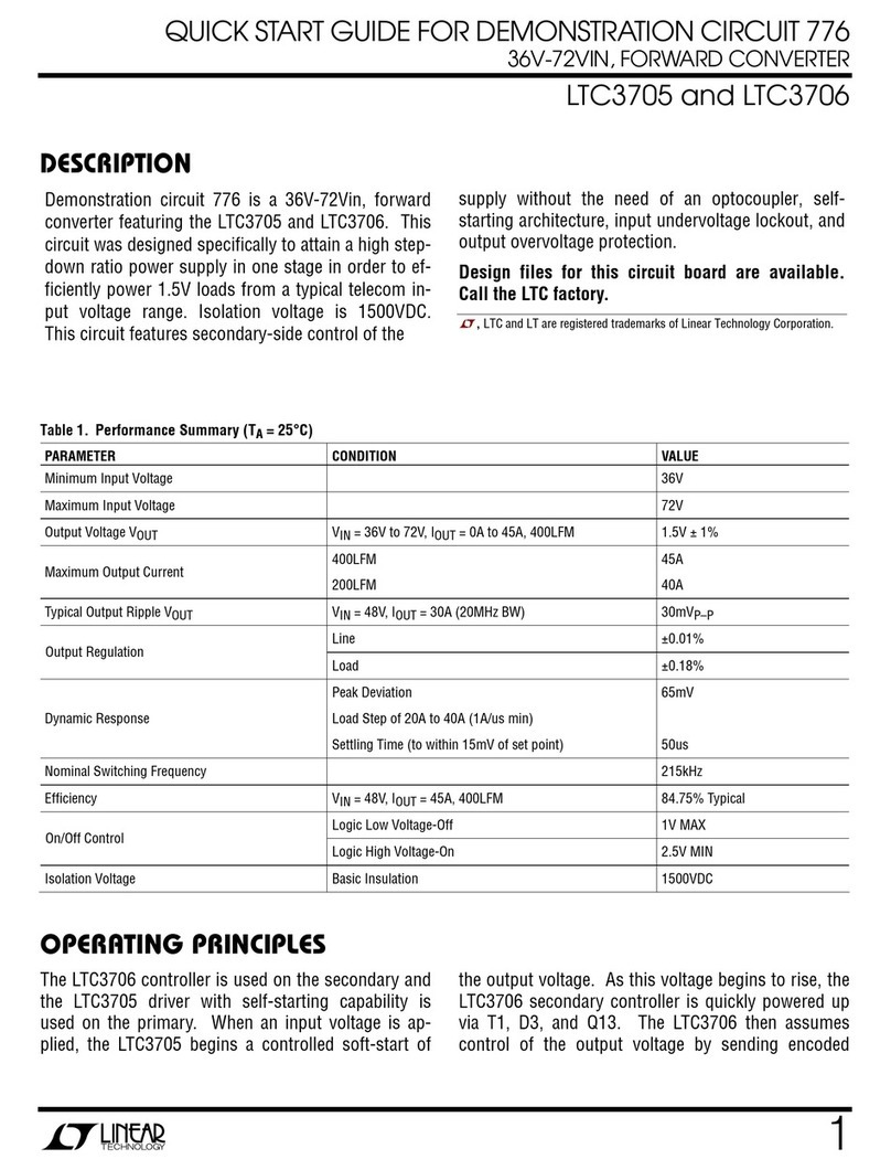
Linear Technology
Linear Technology DC776 User manual

Linear Technology
Linear Technology DC1639A User manual
Popular Motherboard manuals by other brands
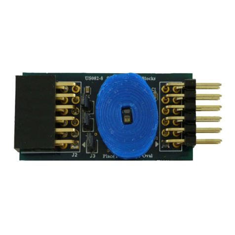
Renesas
Renesas US082-OB1203EVZ manual
Freescale Semiconductor
Freescale Semiconductor Qorivva MPC5746R-176DS user guide
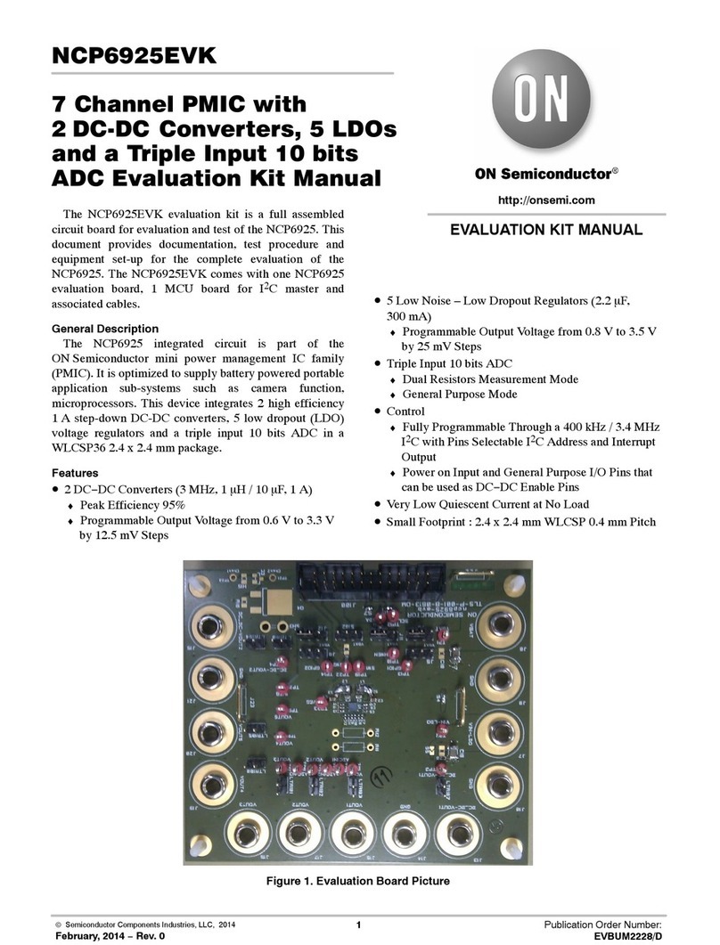
ON Semiconductor
ON Semiconductor NCP6925EVK manual
ASROCK
ASROCK 870 EXTREME user manual
Vox Technologies
Vox Technologies ROCKY 538TXV manual
Analog Devices
Analog Devices EZ-KIT Lite ADSP-BF533 manual

