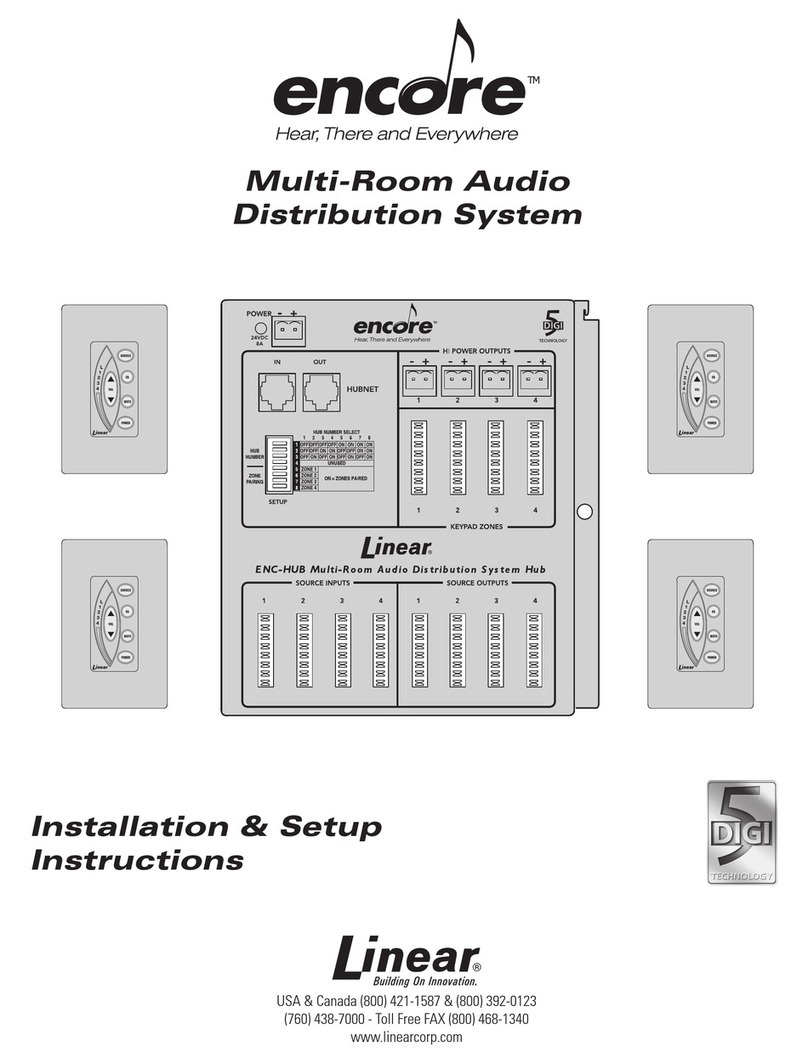
Linear Encore User manual

USA & Canada (800) 421-1587 & (800) 392-0123
(760) 438-7000 - Toll Free FAX (800) 468-1340
www.linearcorp.com
PRINTER’S INSTRUCTIONS:
INSTR,USER MANUAL,ENCORE - LINEAR P/N: 228171 A - INK: BLACK - MATERIAL: 20 LB. MEAD BOND - SIZE: 5.500” X 8.500” - SCALE: 1-1 - FOLDING: ALBUM-FOLD - BINDING: SADDLE-STITCH
Multi-Room Audio
Distribution System
User’s Guide

Safety Information and Cautions
Explanation of Graphic Warning Symbols
This symbol is intended to alert the user to the presence
of un-insulated “dangerous voltage” within the product’s
enclosure that may be of sufficient magnitude to constitute
a risk of electric shock.
This symbol is intended to alert the user to the presence of
important operating and maintenance (servicing) instructions
in the literature accompanying the device.
★ WARNING! To prevent fire or shock hazard, do not
expose this device to rain, water, or wet locations.
General Wiring Cautions
DO NOT USE EXCESSIVE FORCE ON PUNCH-DOWN•
TERMINALS! IF USING AN IMPACT TYPE 110 PUNCH-DOWN
TOOL, SET THE FORCE ADJUSTMENT TO “LOW” BEFORE
TERMINATING CAT-5 CABLES.
The 120 VAC line to the structured wiring enclosure’s junction•
box must be run by a licensed electrician.
Individual CAT-5 cable runs from the hub to any keypad or audio•
input wall plate should not exceed 500 feet.
Label all cables for identification at the hub.•
DO NOT SPLICE CABLES! Splices are unreliable and defeat the•
signal isolation properties of the cable.
DO NOT STAPLE CABLES! Staples cause shorts.•
DO NOT RUN 120 VAC ELECTRICAL WIRES INSIDE STATION•
JUNCTION BOXES. If you encounter 120 VAC wires running
through station junction boxes, you must have a qualified
electrician rerun those wires around the junction box.
KEEP CABLES AT LEAST 18 INCHES FROM FLORESCENT•
LIGHT FIXTURES, DIMMER CONTROLS, AND ALL OTHER
WIRING. This includes AC wiring, security cable, cordless
phone units, and other control wires. These can cause a “hum”
or “buzzing” sound.
Keep all cables away from objects such as heating and air•
conditioning ducts, metal construction plates, and anything else
with sharp edges that can damage cables.
Keypad Cautions
DO NOT install room stations in saunas. They will not withstand•
the extreme heat or moisture.
Important Safety Notes
POWER SOURCE This unit should only be connected to a
110-120 VAC power source as marked on the unit.
GROUNDING OR POLARIZATION Do not defeat the
safety purpose of the polarized or grounding-type plug. A
polarized plug has two blades with one wider than the other.
A grounding type plug has two blades and a third grounding
prong.The wide blade or the third prong are provided for your
safety. If the provided plug does not fit into your outlet, consult
an electrician for replacement of the obsolete outlet.
NON-USE PERIODS Always turn the unit off and unplug
when it is not being used or left unattended for long periods
of time.
OBJECT AND LIQUID ENTRY Never push objects of any
kind into the unit through the cabinet slots as they may touch
dangerous voltage points or short out parts that could result
in a fire or electric shock. Never spill liquid of any kind on
the unit.
CLEANING Unplug the unit from the wall outlet before
cleaning or polishing it. Do not use liquid cleaners, aerosol
cleaners, gasoline or other flammable fluid. Clean the exterior
of the unit with a slightly damp cloth.
WATER AND MOISTURE Do not use power line operated
units near water - for example, near a bathtub, washbowl,
kitchen sink, or laundry tub, in a wet basement, or near a
swimming pool.
VENTILATION The appliance should be situated so that
its location or position does not interfere with its proper
ventilation. For example, the unit should not be situated on a
bed, sofa, rug or placed in a built-in installation that may block
the flow of air through the ventilation openings.
POWER CORD PROTECTION Power supply cords should be
routed so that they are not likely to be walked on or pinched
by items placed upon or against them paying particular
attention to cords at plugs, convenience receptacles, and the
point where they exit from the appliance.
READ INSTRUCTIONS All the safety and operating
instructions should be read before the product is operated.
RETAIN INSTRUCTIONS The safety and operating
instructions should be retained for future reference.
HEED WARNINGS All warnings on the product and in the
operating instructions should be adhered to.
FOLLOW INSTRUCTIONS All operating and use instructions
should be followed.
ATTACHMENTS Do not use attachments not recommended
by the product manufacturer as they may cause hazards.
ACCESSORIES Do not place this product on an unstable
cart, stand, tripod, bracket, or table. The product may
fall, causing serious injury to a child or adult, and serious
damage to the product. Use only with a cart, stand, tripod,
bracket or table recommended by the manufacturer, or sold
with the product. Any mounting of the product should follow
the manufacturer’s instructions, and should use a mounting
accessory recommended by the manufacturer.
OVERLOADING Do not overload wall outlets, extension
cords, or integral convenience receptacles as this can result
in a risk of fire or electric shock.
REPLACEMENT PARTS When replacement parts
are required, be sure the service technician has used
replacement parts specified by the manufacturer or have
the same characteristics as the original part. Unauthorized
substitutions may result in fire, electric shock, or other
hazards.
SAFETY CHECK Upon completion of any service or repairs
to this product, ask the service technician to perform safety
checks to determine that the product is in proper operating
condition.
WALL OR CEILING MOUNTING The product should be
mounted to a wall or ceiling only as recommended by the
manufacturer.
HEAT The product should be situated away from heat
sources such as radiators, heat registers, stoves, or other
products (including amplifiers) that produce heat.

CAUTION
RISK OF ELECTRIC SHOCK
DO NOT OPEN
CAUTION: TO REDUCE THE RISK OF ELECTRIC SHOCK
DO NOT REMOVE COVER (OR BACK)
NO USER-SERVICEABLE PARTS INSIDE
REFER SERVICE TO QUALIFIED PERSONNEL

1
Table of Contents
Introduction - Your Multi-Room Audio System ................................................................. 2
Keypads .......................................................................................................................... 2
Source Inputs.................................................................................................................. 2
Local Inputs..................................................................................................................... 2
Remote Control............................................................................................................... 2
Features .......................................................................................................................... 2
System Overview................................................................................................................. 3
Keypad Features.................................................................................................................. 4
Audio Source Wall Plate Features...................................................................................... 5
System Operation................................................................................................................ 6
Power On/Off................................................................................................................... 6
Keypad Power On..................................................................................................... 6
Keypad Power Off..................................................................................................... 6
Entire System Power Off .......................................................................................... 6
Source Select.................................................................................................................. 6
Changing the Audio Source...................................................................................... 6
Volume Control................................................................................................................ 6
Turning the Volume Up or Down ............................................................................... 6
Audio Mute ...................................................................................................................... 6
Muting the Keypad’s Sound ...................................................................................... 6
Whole-house Mode......................................................................................................... 7
Playing the Same Source at all Keypads.................................................................. 7
Do Not Disturb Mode ................................................................................................ 7
Equalizer & Audio Dynamics........................................................................................... 8
Adjusting the Keypad’s Sound .................................................................................. 8
Bass Adjust............................................................................................................... 8
Treble Adjust ............................................................................................................. 8
Balance Adjust.......................................................................................................... 8
Loudness On/Off ...................................................................................................... 8
Limiter/Compressor On/Off....................................................................................... 8
Remote Controls ............................................................................................................. 9
Basic Remote ........................................................................................................... 9
Learning Remote...................................................................................................... 9
Specifications .................................................................................................................... 10
Limited Warranty................................................................................................................ 10

2
Introduction - Your Multi-Room Audio System
Your Encore Multi-Room Audio System
is an expandable system that distributes
four analog or digital audio sources to
independent stereo speaker zones
located in different rooms. With the
appropriate amount of system “hubs”,
each installation can distribute audio to
a maximum of 32 speaker zones.
Keypads
Each speaker zone features a backlit
keypad with an integrated digital
amplifier. The keypads provide the
ability to select up to five audio sources
and control the volume, tone, balance,
loudness, and several other functions
of the system.
Source Inputs
Your installation includes up to four
Source Input Wall Plates that serve
as a connection point for your audio
equipment. Audio outputs from your
source components connect to these
wall plates providing audio to the
system hub for distribution to each
keypad.
Local Inputs
In rooms with a keypad, a Local Input
Wall Plate may also be installed.These
serve as a connection point for a local
audio source, such as an mp3 player,
TV, computer, or game box.
Remote Control
The system features infrared (IR)
remote control.Two remote controls are
available. The Basic Remote Control
is a miniature unit that can select the
audio source, control the volume,
mute, and power. The larger Learning
Remote Control has all of the features
of the basic remote with the addition of
a built-in IR code library and IR learning
capability allowing it to control virtually
any audio source component through
the system. The learning remote also
has macro capabilities that allow
programming multiple key sequences.
At each keypad, IR signals received
from any IR remote control are passed
onto your audio source components
allowing you to use your standard
remote controls.
Features
Digital audio delivers crystal•
clear sound to all zones
with no signal loss
Class D digital amplifier in each•
keypad with 60 watts output power
Four speaker zones expandable•
to 32 speaker zones
IR receiver built into each room•
station, IR emitter output on
source input wall plates

3
System Overview
The diagram below shows how the
signals flow through your Multi-Room
Audio System.
Audio from the source components
enter the source input wall plates and
are routed to the system “hub”. The
system hub is usually hidden in a
wiring cabinet.
The keypads also connect to the
system hub. Each keypad can select
any of the sources connected to the
hub.
Each keypad connects to a pair of
stereo speakers. Each keypad has an
integrated built-in digital amplifier to
power its speakers.
All the audio signals, from the wall
plates to the hub, and from the hub to
the keypads are “digital”. Any analog
audio sources connected to the wall
plates are converted to digital audio
signals. The digital signals provide
crystal clear sound to all zones with no
signal loss.
STEREO
SPEAKERS
KEYPAD
LOCAL INPUT
WALL PLATE
MP3
PLAYER
GAME
BOX
SOURCE INPUT
WALL PLATE
CD PLAYER
SATELLITE RADIO
COMPUTER
TUNES
STEREO
RECEIVER
ZONE 1
ZONE 2
ZONE 3
ZONE 4
IR EMITTER
TO SOURCE
COMPONENT
SYSTEM
HUB
HUB HIDDEN IN
WIRING CABINET
SOURCE 1
SOURCE 2
SOURCE 3
SOURCE 4
AUDIO FROM
SOURCES
AUDIO FROM
SOURCES
AUDIO TO
KEYPADS
AUDIO TO
KEYPADS
LOCAL AUDIO
SOURCE
AMPLIFIED AUDIO
TO SPEAKERS
EACH KEYPAD CAN PLAY AUDIO FROM
ANY OF THE FOUR SOURCES OR FROM A
LOCAL SOURCE IF AVAILABLE
LOCAL INPUT
WALL PLATE
LOCAL AUDIO
SOURCE
SOURCE INPUT
WALL PLATE
SOURCE INPUT
WALL PLATE
SOURCE INPUT
WALL PLATE
STEREO
SPEAKERS
STEREO
SPEAKERS
STEREO
SPEAKERS
KEYPAD
KEYPAD
KEYPAD

4
POWER BUTTON
PRESS TO TURN KEYPAD POWER ON OR OFF
PRESS FOR 3 SECONDS TO TURN POWER OFF
ON ALL KEYPADS
MUTE BUTTON
PRESS TO MUTE THE KEYPAD'S SPEAKERS
TO UN-MUTE THE SPEAKERS, PRESS MUTE AGAIN
PRESSING VOL OR SOURCE BUTTONS WILL ALSO UN-MUTE
THE KEYPAD'S SPEAKERS
PRESS AND HOLD FOR 3 SECONDS TO DISABLE OR ENABLE
WHOLE-HOUSE MODE FOR THIS KEYPAD
EQ BUTTON (EQUALIZER)
PRESS TO ADJUST EQ SETTINGS
USE SOURCE BUTTON TO CYCLE THROUGH OPTIONS
USE VOL BUTTONS TO ADJUST LEVELS
BASS ADJUST - SOURCE 1 LIGHT FLASHING
TREBLE ADJUST - SOURCE 2 LIGHT FLASHING
LEFT/RIGHT BALANCE ADJUST - SOURCE 3 LIGHT FLASHING
LOUDNESS (BASS BOOST) ON/OFF - SOURCE 4 LIGHT FLASHING
LIMITER/COMPRESSOR ON/OFF - LOCAL SOURCE LIGHT FLASHING
VOLUME LIGHTS
DISPLAYS THE KEYPAD'S VOLUME SETTING
ALSO USED TO DISPLAY EQUALIZER SETTINGS
SOURCE BUTTON
PRESS TO SELECT ONE THE FOUR HUB SOURCES
OR THE LOCAL (L) KEYPAD INPUT SOURCE
PRESS AND HOLD FOR 3 SECONDS TO
TURN WHOLE-HOUSE MODE ON OR OFF
VOLUME BUTTON
PRESS UP ARROW TO INCREASE VOLUME
PRESS DOWN ARROW TO DECREASE VOLUME
ALSO USED FOR ADJUSTMENTS IN EQ MODE
SOURCE INDICATORS
INDICATORS LIGHT TO SHOW THE SELECTED
AUDIO SOURCE FOR THE KEYPAD
INDICATORS BLINK IN EQUALIZER ADJUST
AND PARTY MODES
INFRARED SENSOR
DETECTS INFRARED SIGNALS FROM
REMOTE CONTROLS
INFRARED SIGNALS ARE PASSED ON TO
THE SOURCE COMPONENTS
Keypad Features
The keypads control the system’s
power and all its functions. The system
can be controlled by any keypad in the
installation.
The keypads have soft blue lighting
that stays on for about 20 seconds after
any key is pressed. As a power-saving
feature, after 20 seconds the keypad
lighting will slowly dim
The system and audio source
components can be operated by
pointing the appropriate IR remote
control at the keypad.

5
Audio
In
LR
Coax In Optical In
Analog
Optical
Coax
IR Out
Clip
Audio
In
LR
1
2
Coax In
Optical In
Analog
Optical
Coax
IR Out
Clip
ANALOG AUDIO INPUT
LEFT AND RIGHT COLOR CODED "RCA" TYPE JACKS
FOR LINE-LEVEL ANALOG AUDIO OUTPUT FROM THE
AUDIO SOURCE COMPONENT
SOURCE INPUT WALL PLATE
LOCAL INPUT WALL PLATE
CLIPPING INDICATOR
LIGHTS IF THE AUDIO INPUT
SIGNAL LEVEL IS TOO HIGH
OPTICAL DIGITAL AUDIO INPUT
"SPDIF" TYPE CONNECTOR FOR FIBER OPTIC
CABLE CONNECTION TO THE AUDIO OUTPUT
FROM THE AUDIO SOURCE COMPONENT
COAXIAL DIGITAL AUDIO INPUT
"RCA" TYPE CONNECTOR FOR COAX
CABLE CONNECTION TO THE DIGITAL AUDIO
OUTPUT FROM THE AUDIO SOURCE COMPONENT
USE ONE OF THESE
INPUTS FOR THE
BEST SOUND
INPUT SELECTOR SWITCH
SET THE SWITCH TO MATCH THE TYPE OF INPUT
USED, ANALOG, OPTICAL, OR COAX
INFRARED (IR) OUTPUT JACK
PLUG IR EMITTER INTO THIS JACK AND AFFIX THE EMITTER
TO THE FACEPLATE OF THE SOURCE COMPONENT TO ALLOW
REMOTE CONTROL OF COMPONENT FROM REMOTE KEYPADS
ANALOG AUDIO INPUTS #1 & #2
LEFT AND RIGHT COLOR CODED "RCA" TYPE JACKS
FOR LINE-LEVEL ANALOG AUDIO OUTPUT FROM THE
AUDIO SOURCE COMPONENT.
INPUT #1 AUTOMATICALLY
OVERRIDES ANY OF THE OTHER INPUTS WHEN AUDIO
IS DETECTED ON INPUT #1 REGARDLESS OF THE INPUT
SELECTOR SWITCH POSITION.
CLIPPING INDICATOR
LIGHTS IF THE AUDIO INPUT
SIGNAL LEVEL IS TOO HIGH
OPTICAL DIGITAL AUDIO INPUT
"SPDIF" TYPE CONNECTOR FOR FIBER OPTIC
CABLE CONNECTION TO THE AUDIO OUTPUT
FROM THE AUDIO SOURCE COMPONENT
COAXIAL DIGITAL AUDIO INPUT
"RCA" TYPE CONNECTOR FOR COAX
CABLE CONNECTION TO THE DIGITAL AUDIO
OUTPUT FROM THE AUDIO SOURCE COMPONENT
USE ONE OF THESE
INPUTS FOR THE
BEST SOUND
INPUT SELECTOR SWITCH
SET THE SWITCH TO MATCH THE TYPE OF INPUT
USED, ANALOG #2, OPTICAL, OR COAX
INFRARED (IR) OUTPUT JACK
PLUG IR EMITTER INTO THIS JACK AND AFFIX THE EMITTER
TO THE FACEPLATE OF THE SOURCE COMPONENT TO ALLOW
REMOTE CONTROL OF COMPONENT FROM REMOTE KEYPADS
Audio Source Wall Plate Features
The audio source wall plates provide
a system connection point for your
audio source components. Local audio
source wall plates may also be installed
in your system.
Line-level analog, coaxial digital, or an
optical digital output from your audio
source component can be used.
✓ NOTE: For the best quality sound,
use your source component’s digital
output if it has one.
The wall plates have an IR output jack
that an infrared emitter can connect to.
The emitter attaches to the faceplate
of the source component and allows IR
remote control from keypad locations.

6
System Operation
Power On/Off
Keypad Power On
Press the• POWER button on the keypad.
The keypad will light blue when the power
is turned on.
Keypad Power Off
While the keypad is powered, press the•
POWER button on the keypad.
Entire System Power Off
Press and hold the• POWER button for
about three seconds. All keypads in the
entire system will power off.
Source Select
Changing the Audio Source
Press the• SOURCE button on the keypad
to change the audio source.
The source indicators will light to show•
which audio source is selected; L(Local),
1, 2, 3, or 4.
Volume Control
Turning the Volume Up or Down
Press• VOL ▲to increase the keypad’s
volume.
Press• VOL ▼to decrease the keypad’s
volume.
The volume indicators will show the set•
level. The more indicators lit, the louder the
volume.
Audio Mute
Muting the Keypad’s Sound
While the audio is playing, press the• MUTE
button to silence the audio.
The bottom volume indicator will blink while•
mute is active.
Press the• MUTE button again to return the
keypad to its previous volume setting.
Pressing the• VOL ▲or SOURCE buttons
will also return the keypad to its previous
volume setting.
Pressing• VOL ▼will un-mute the audio
and set the keypad to minimum volume
level.
POWER BUTTON
SOURCE BUTTON
VOLUME BUTTON
MUTE BUTTON

7
System Operation
Whole-house Mode
Playing the Same Source at all Keypads
Press the• SOURCE button for about
three seconds to enter or exit whole-house
mode.
The selected audio source indicator will•
blink on and the same audio will play at all
keypads.
If a keypad is set for do not disturb mode, it•
will not play the source (see below).
The volume control is independent for•
each keypad.
Pressing the• SOURCE button on any
keypad will change the audio source;
1, 2, 3, or 4for all keypads that are in
whole-house music mode.
Audio from local audio wall plates (source• L)
cannot be the whole-house source.
Do Not Disturb Mode
Press a keypad’s• MUTE button for about
three seconds to prevent the individual
keypad from allowing whole-house mode.
The keypad will flash to display that if•
whole-house mode is selected by another
keypad, this keypad will not participate.
To allow whole-house mode for the keypad,•
press the MUTE button again for about
three seconds.
PRESS SOURCE BUTTON
FOR 3 SECONDS
SELECTED SOURCE
LIGHT WILL BLINK
SELECTED SOURCE
LIGHT WILL BLINK
ON ALL KEYPADS
IN WHOLE-HOUSE MODE
EACH KEYPAD HAS
INDEPENDENT VOLUME
CONTROL
PRESS MUTE BUTTON
FOR 3 SECONDS TO
DISABLE WHOLE-HOUSE
MODE FOR A KEYPAD
VOLUME LIGHTS
WILL FLASH

8
System Operation
Equalizer & Audio Dynamics
Adjusting the Keypad’s Sound
Press the• EQ button to enter equalizer
adjustment mode. Press EQ again to exit.
Equalizer adjustment mode automatically•
exits after 30 seconds of keypad inactivity.
The source indicators will light up, then one•
will flash to indicate that the keypad is in
equalizer adjustment mode.
Use the SOURCE button to cycle•
through the five adjustment modes.
Bass Adjust
When source indicator• 1is flashing, the
keypad is in bass adjust mode.
The center volume indicator will light,•
showing a “flat” adjustment for the bass, no
bass increase or decrease.
Use the• VOL ▲and VOL ▼buttons to
adjust the bass level. Lit indicators above
the center show more bass. Lit indicators
below the center show less bass.
Treble Adjust
When source indicator• 2is flashing, the
keypad is in treble adjust mode.
The center volume indicator will light,•
showing a “flat” adjustment for the treble,
no treble increase or decrease.
Use the• VOL ▲and VOL ▼buttons to
adjust the treble level. Lit indicators above
the center show more treble. Lit indicators
below the center show less treble.
Balance Adjust
When source indicator• 3is flashing, the
keypad is in balance adjust mode.
The center volume indicator will light,•
showing a “center” adjustment for the
balance, no extra left or right.
Use the• VOL ▲and VOL ▼buttons to
adjust the balance. Lit indicators above
the center show more right balance. Lit
indicators below the center show more left
balance.
Loudness On/Off
When source indicator• 4is flashing, the
keypad is in loudness setting mode.
When the loudness setting is on, extra•
bass is added to improve the sound when
listening at low volume levels.
Use the• VOL ▲button to turn this option
on (the top volume indicator lights).
Use the• VOL ▼button to turn this option off
(the bottom volume indicator lights).
Limiter/Compressor On/Off
When source indicator• Lis flashing, the
keypad is in limiter/compressor mode.
Loudness adds extra bass. Limiter/•
compressor automatically limits volume.
Use the• VOL ▲button to turn this option
on (the top volume indicator lights).
Use the• VOL ▼button to turn this option off
(the bottom volume indicator lights).
PRESS VOL UP OR VOL DOWN
TO ADJUST THE LEVEL
BASS & TREBLE ADJUST
CENTER LIGHT
INDICATES A FLAT SETTING
LIGHTS ABOVE CENTER = MORE
LIGHTS BELOW CENTER = LESS
PRESS VOL UP OR VOL DOWN
TO ADJUST THE BALANCE
BALANCE ADJUST
CENTER LIGHT
INDICATES A CENTER BALANCE SETTING
LIGHTS ABOVE CENTER = MORE RIGHT
LIGHTS BELOW CENTER = MORE LEFT
PRESS VOL UP TO TURN LOUDNESS
ON
PRESS VOL DOWN TO TURN LOUDNESS
OFF
LOUDNESS SETTING
TOP LIGHT = LOUDNESS ON
BOTTOM LIGHT - LOUDNESS OFF

9
System Operation
Remote Controls
Basic Remote
The basic remote control can operate the•
system’s source selection, volume, mute,
and power.
The basic remote control sends infrared•
(IR) signals to the keypad that is being
controlled.
For the best operation, be sure to•
point the remote control directly at the
keypad.
To change the keypad’s source, press the•
SRC ▲or SRC ▼buttons.
To change the keypad’s volume, press the•
VOL ▲or VOL ▼buttons.
To mute the keypad’s sound, press the•
MUTE button.
To control the keypad’s power, press the•
PWR button.
Learning Remote
The learning remote control performs all•
the functions of the basic remote control,
plus all the other functions that can be
controlled by a keypad.
Up to four source devices as well as your•
audio distribution system can be operated
with the learning remote control.
The learning remote control can “learn” IR•
commands from other IR remote controls
and be programmed with up to three key
macros.
For the best operation, be sure to•
point the remote control directly at the
keypad.
Refer to the instruction sheet packed with•
the learning remote control for details on
its operation.
Basic Remote Control
Learning Remote Control
STEREO
SPEAKERS
KEYPADSOURCE INPUT
WALL PLATE
CD PLAYER
IR EMITTER ON SOURCE
COMPONENT FACE REPEATS
THE IR SIGNALS FROM THE
REMOTE CONTROL
SYSTEM
HUB
HUB HIDDEN IN
WIRING CABINET
INFRARED
SIGNALS
INFRARED (IR) SIGNALS FROM REMOTE CONTROLS
POINTED AT A KEYPAD WILL BE SENT BACK
TO YOUR AUDIO SOURCE COMPONENTS
ENC-REM
BASIC REMOTE
CONTROL
INFRARED
SIGNALS
CONTROL YOUR COMPONENTS
FROM ANY KEYPAD LOCATION

This Linear product is warranted against defects in material and workmanship for twenty
four (24) months. This warranty extends only to wholesale customers who buy direct
from Linear or through Linear’s normal distribution channels. Linear does not warrant this
product to consumers. Consumers should inquire from their selling dealer as to the nature
of the dealer’s warranty, if any. There are no obligations or liabilities on the part of Linear
LLC for consequential damages arising out of or in connection with use or performance
of this product or other indirect damages with respect to loss of property, revenue, or
profit, or cost of removal, installation, or reinstallation. All implied warranties, including
implied warranties for merchantability and implied warranties for fitness, are valid only until
the warranty expires. This Linear LLC Warranty is in lieu of all other warranties express
or implied.
All products returned for warranty service require a Return Product Authorization Number
(RPA#). Contact Linear Technical Service at 1-800-421-1587 for an RPA# and other important
details.
USA & Canada (800) 421-1587 & (800) 392-0123
(760) 438-7000 - Toll Free FAX (800) 468-1340
www.linearcorp.com
Copyright © 2009 Linear LLC 228171 A
Limited Warranty
Specifications
Amplified Keypads
Continuous Average Output Power, 8 Ω60 W (2 x 30 W)
(1 kHz sinewave, 2 channels driven 1% THD)
Dynamic Range 96 db
Source Inputs
Source Input Impedance 50 k Ω
Source Input Overload 2.4 Vrms
Sampling Frequency 48 kHZ
Audio Resolution 24 Bit Stereo
Emitter Outputs (1 for each source input)
Output Drive Current 12 mA
Output Drive Voltage 12 VDC
Power Supply
Input 120 VAC 60 Hz, 1.2 A Avg.
Output 26 VDC
Power Consumption Maximum 200 W
Power Consumption Standby 20 W
Regulatory
USA TUV
Canada TUV
Physical Dimensions (D x W x L)
ENC-PS 2.1” x 6.3” x 8.5”
ENC-HUB 1.9” x 6.3” x 6.8”
ENC-DRS 2.6” x 1.8” x 4.1”
ENC-SIWP 2.9” x 1.3” x 4.1”
ENC-LIWP 2.9” x 1.3” x 4.1”
Other manuals for Encore
1
Table of contents
Other Linear Amplifier manuals

Linear
Linear microZOTL User manual

Linear
Linear NOR FOUND ENC-SIWP User manual

Linear
Linear HDMI-DA-1X8 User manual

Linear
Linear H560 User manual

Linear
Linear HDMI-DA-2X8M User manual

Linear
Linear COMP-DA-1X8 User manual

Linear
Linear LT1222 User manual

Linear
Linear Encore Manual

Linear
Linear LT6557 User manual

Linear
Linear COMP-DA-1X3 User manual
Popular Amplifier manuals by other brands

Peavey
Peavey StudioPro 112 user guide

AUSTRALIAN MONITOR
AUSTRALIAN MONITOR Digipage JR Installation & operation manual

Johnson Amplification
Johnson Amplification Marquis JM60 user guide

AUDIOropa
AUDIOropa PRO LOOP D5 LOS user manual

Sansui
Sansui CA-2000 operating instructions

CARVIN
CARVIN DCM200L operating manual