Linear 2 GIG Go!Bridge User manual
Copyright © 2014 Linear LLC 1
2GIG-BRDG1-900
Go!Bridge IP Communicator
INSTALL INSTRUCTIONS
TheGo!Bridge™IPCommunicator(2GIG‐BRDG1‐900)provides
Internetconnectivitybetweenthemonitoringservice’sCentralStation
andtheGo!Control®Panel(requiresthe900MHzTransceiver(2GIG‐
XCVR)).
Itsupportsautomaticfirmwareupdates,providesinteractivesecurity
services,andincreasessupervisionusingsignal‐forwardingtothe
CentralStation.Tocommunicatewirelesslywiththecontrolpanel,the
900MHzTransceiverModule(2GIG‐XCVR)mustbeinstalledinthe
panelandtheGo!Bridgemustbeconnectedtothelocalnetwork
routerusinganEthernetcable(notprovided).
Box Contents
Verifythatthepackageincludesthefollowing:
•1—Go!Bridge
•1—5‐VDCUSBMini‐BPowerSupply
•1—Stand
Requirements
Beforeyouinstall,program,andtesttheGo!Bridge,ensurethecontrol
panelbeingpairedwiththeGo!Bridgemeetstheserequirements:
•FirmwareVersion1.12(orhigher)
•2GIG‐XCVR900MHzTransceiver
NOTE: Toprotectdatasentviathelocalwirelessnetwork,isit
recommendedthatyouinstalltheGo!Bridgeonalocal
networkwhereWPA(Wi‐FiProtectedAccess)orWEP(Wire
EquivalentPrivacy)Encryptionisalreadyenabled.
Afterinstalling,programming,andtestingtheGo!Bridge,youwillneed
toregisteranewcustomerwiththethird‐partymonitoringservice.
SeeRegistrationonpage2.
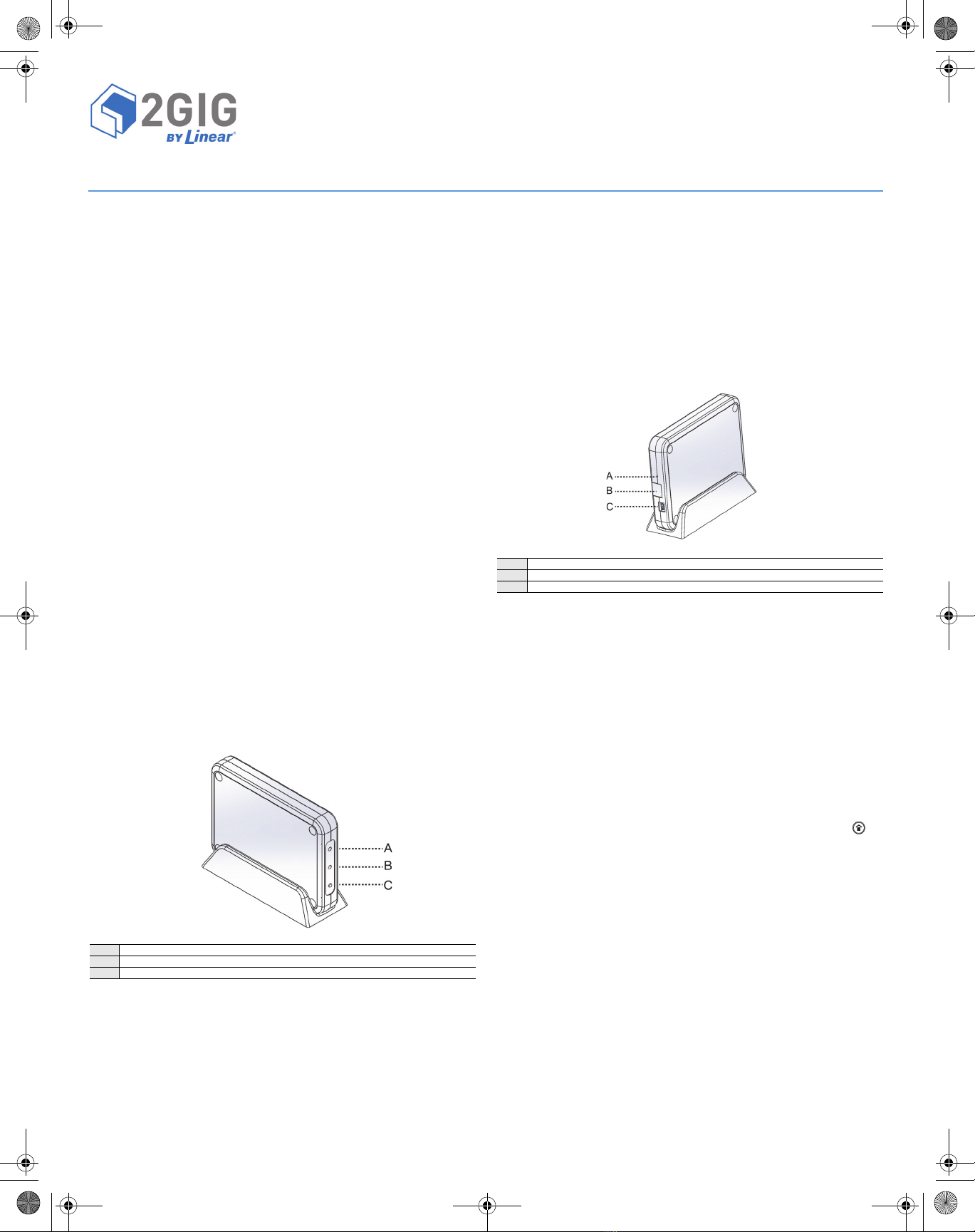
Figure 1 Go!Bridge Front View—LED Indicators and Learn Button
Powering ON the Go!Bridge
UsethesestepstopowerONtheGo!Bridge:
1EnsuretheGo!Bridgeisconnectedtoapowersource.
NOTE: DonotconnectanEthernetcabletotheGo!Bridgeatthis
time.Youwillconnectthecablewhencompletingthestepsin
ProgrammingtheGo!BridgeintotheControlPanel.
2(Optional)Placethestand(provided)onacounter,desktop,or
otherflatsurface.SettheGo!Bridgeinthestand.
3VerifythatthetwoLEDsontheGo!BridgeilluminateinRED(see
Figure1Go!BridgeFrontView—LEDIndicatorsandLearnButton).
NOTE: Ifthe900MHzLEDilluminatesinGREEN(thelowerLED),
verifythatthenetworkcableisnotconnectedtothe
Go!Bridge.Ifthecableisdisconnectedanditisstillilluminated
GREEN,usetheendofanopenpapercliptopressandrelease
therecessedResetbutton.Thebuttonislocatedinsidethe
smallholeontheportsideoftheGo!Bridge,directlyabove
theEthernetport.Thisrestoresthefactorysettings.SeeFigure
2Go!BridgeRearView—PortsandRecessedResetButton.
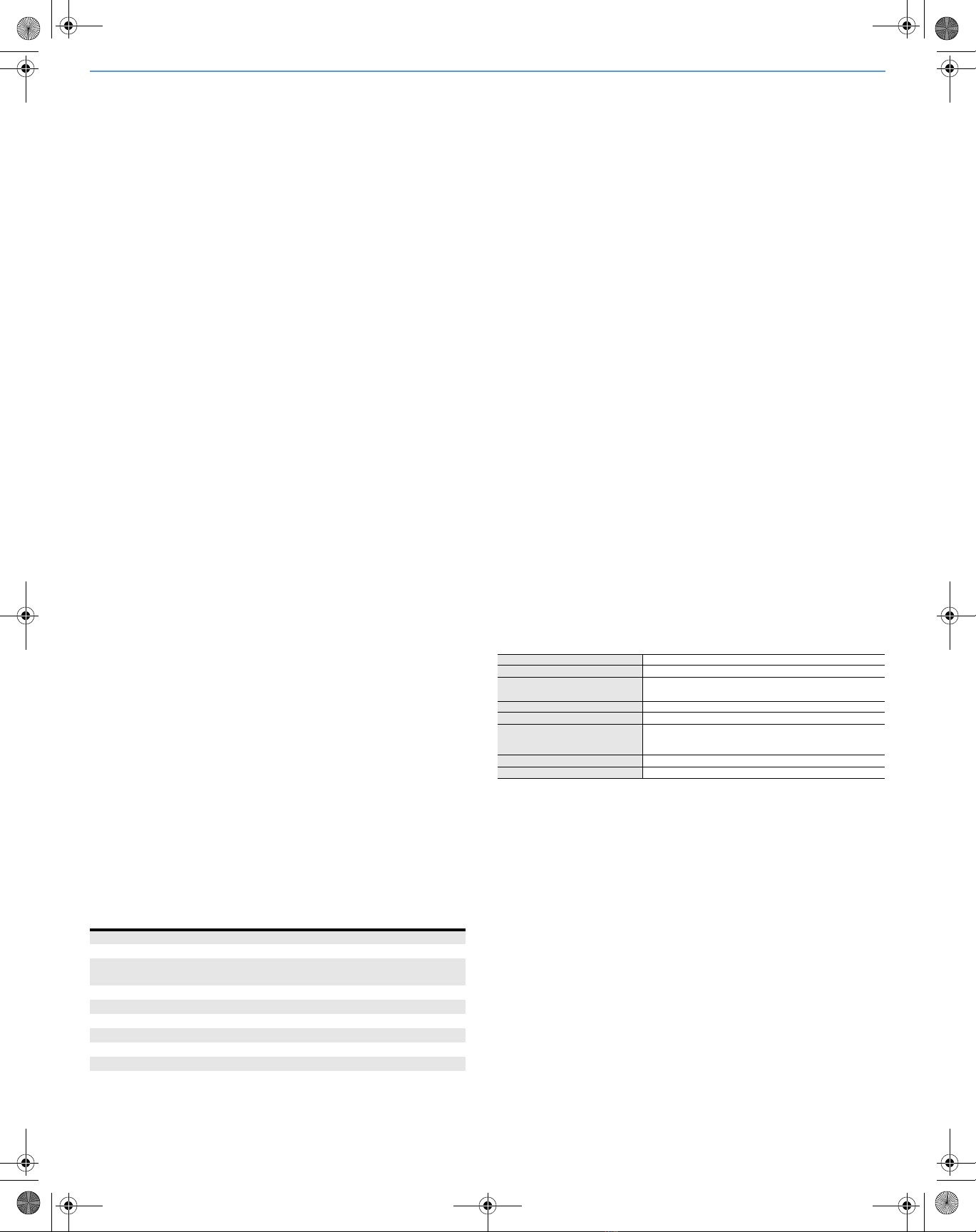
Figure 2 Go!Bridge Rear View—Ports and Recessed Reset Button
4AftertheGo!BridgeispoweredON,continuewithProgramming
theGo!BridgeintotheControlPanel.
Programming the Go!Bridge into the Control
Panel
UsethesestepstoplacethecontrolpanelandGo!Bridgeinlearning
mode.Thisgivesthecontrolpaneltheabilitytolearnthenetwork
settingstransmittedbytheGo!Bridge.
NOTE: Toscrollbetweenoponsonthecontrolpanel,tapthe←
and→arrows.Tomovetothepreviousornextprompttapthe
↑and↓arrows.
1ConnectanEthernetcable(notincluded)totherouterand
Go!Bridge.
2EnsurethecontrolpanelispoweredON.ThentaptheHome
button.
3Tapthesystemlogointhelower‐rightcornerofthecontrolpanel
Homescreen.
4AttheEnterYourCodepage,enteryour4‐digitinstallercodetogo
totheInstallerToolbox(page1of2)page.
5AttheInstallerToolbox(page1of2)page,tapSystem
Configuration.
6AttheQ1:SelectRFSensor#(01to48)page,tapGoTo.
7AttheEnterQuestionNumber(2Digits)page,enter92.
8AtQ92SelectNetworkDevice(0to1),tap→toscrollto(1)
Go!Bridge.Thentap↓.
9AtQ:NetworkDeviceID(ReadOnly),tapLearn.Thisgivesthe
paneltheabilitytodiscovertheread‐onlynetworkdeviceID
transmittedbytheGo!Bridge.
AtthePairwithXcvrDevicepage,the“initiatinglearningprocess”
messageappears.
ANetworkLED
B 900MHzLED
CLearnbutton
ARecessedResetbutton
BEthernetport
CPowersupplyport
INSTRUCTIONS: FILE: 77-000044-001-BRDG1-900-INSTALL-INSTRUCTIONS-REVB-PRT-EN.PDF - DATE: 5/5/2014 - INK: BLACK - MATERIAL: 20 LB MEAD BOND - SIZE: 8.5"X11" - SCALE: 1 - PRINTING: FRONT AND BACK - FOLDING: FOLD TO FIT IN BOX - PAGES: 3
2Copyright © 2014 Linear LLC
10 OntheGo!Bridge,pressandreleasethelearnbutton(thisisthe
small,blackplasticbuttonontheLEDsideoftheGo!Bridgebelow
the900MHzLED).ThistransmitsthedeviceIDtothecontrolpanel.
Whenthe“learnoperationsucceeded”messageappearsandthe
paneldisplaystheType(Go!Bridge)andID#,theGo!Bridgeand
panelarelinked.The900MHzLEDontheGo!Bridgealsoflashes
GREEN.
11 AtthePairwithXcvrDevicepage,tapOK.Thentap↓tocontinue
withConfiguringtheGo!BridgeSettingsbelow.
Configuring the Go!Bridge Settings
ToconfiguretheGo!Bridgesettings:
1AttheQ:SelectConfigurationSource(0to1)screentap→to
selectthe(0)DHCPsetting.ThisassignstheGo!BridgeanIP
Addressonthelocalnetwork.ItisrecommendedthatyoutapNext
toskipsteps2‐3andcontinuewithstep4.
2Ifyoutap↓(insteadofNext)instep1above,theQ:SelectPort#
(1to8)pageappears.Entertheportnumberforthethird‐party
monitoringservices’server.Thentap↓.
3AtQ:Used(0to1),tap→toselectoneoftheseoptions:
•(0)Disabled(Recommended).Thisisthedefaultsetting.Then
tapNextandskiptostep4.
OR
•(1)Enabled.Thentap↓.AttheQ:EnterPortValue(0‐65535)
screen,tap↓toacceptthedefaultportvalue.Next,attheQ:
EnterPortForwardIPAddressscreen,tap↓toacceptthe
addressconfiguredbytheprovider.Youcanconfigureupto
eight(8)ports.Ifyouarefinishedconfiguringports,tapNext.
4AttheSummaryofNetworkDevicepage,tap↓.Verifythelistof
portnumbersandforwardIPaddressesappearsasprogrammed.
ThentapSkip.
5AtQ93EnterBroadbandNetworkFailureTime(1to255),enter
thedesirednumberofminutesthatmustpassbeforeanetwork
failuretriggersthecontrolpaneltoissueatroublealert.The
defaultvalueis30minutes.Thentap↓.
NOTE: Atroublealertconsistsofanaudiblebeepandthecontrol
panel’sHomescreendisplaysatroublemessage.
6AtQ94SelectBroadbandNetworkFailureReport(0or1),tap→
toselectwhetherornottoreportthebroadbandnetworkfailure
tothemonitoringservice:
•(1)Enabled.Thisisthedefaultsetting.Networkfailuresare
reportedtomonitoringservice.
OR
•(0)Disabled.Networkfailuresarenotreported.
7TapEnd.
8AttheSummaryofSystemConfigurationpage,verifythesettings.
ThentapSaveChanges.
9TapExittotheclosetheSystemConfiguration.
LED Indicators
ThetablebelowdetailstheLEDcolorsfortheGo!Bridge:
Verifying the Settings
InadditiontoverifyingthesettingsafterconfiguringtheGo!Bridge,
youcanalsoverifythesettingsatanytimeasfollows:
1AtthecontrolpanelHomescreen,tapSecurity.
2TapMenu.
3TapToolbox.
4IntheEnterYourCodetoAccesstheToolboxpage,enterthe
mastercode.
5Tap→toscrolltotheToolbox(3of3)page.ThentapGo!Bridge
Status.
Asummarypagedisplaysthefollowinginformation:
•NetworkConfiguration.TheDHCPconfigurationsource.
•IPAddress.TheIPAddressfortheGo!Bridge.Thisisa32‐bit
numericaddressthatidentifiesthedeviceonthenetwork.
•SubnetMask.Thesubnetmaskforthenetwork.Alldevices
thatarejoinedtoanetworkbelongtoasubnetwork.
•Gateway.TheIPAddressfortheaccesspointtotheexternal
network.Typically,thisistheIPAddressofthelocalnetwork
routerornodethatcontroltrafficforyourISP.
•MACAddress.ThisistheMediaAccessControl(MAC)Address.
ItisaphysicaladdressthatisencodedtotheGo!Bridgeduring
themanufacturingprocess.
Testing
TheGo!Bridgeteststhenetworkconnectiontothethird‐party
monitoringservice.AreportshowsifGo!Bridgehassuccessfully
connected(orfailedtoconnect)totheexternalserver.
Registration
ToregistertheGo!Bridgewiththemonitoringservice,refertoyour
specificprovider’sregistrationinstructions.
SPECIFICATIONS
HousingMaterial ABSplasticandpoly‐carbonate
Color White
LEDs Internetand900MHz
Dualcolor(REDandGREEN)
Dimensions(LxWxD) 6.25x4.5x1in
Power 5‐VDCUSBMini‐BPowerSupply
Radio 25channelfrequency‐hoppingspreadspectrum,403kHz
channelspacing(910.2‐920.275MHz),GFSKmodulation,
128kbps,+19dBmmaximumRFpowerout
Ethernet100BASE‐T
SerialtoEthernetProcessor Texas InstrumentsStellarisCortexMS
IMPORTANT NOTE
ShouldthelocalnetworkloseInternetaccessduetoapoweroutage
orinterruption,theGo!Bridgeisnotequippedwithabatterybackup
system.Tobestprepareforpowerfailuresandtoensurethesecurity
systemmaintainsInternetaccesswiththemonitoringserviceforlife‐
safetycommunicationsduringpowerfailures,thelocalnetworkmust
haveadedicatedUninterruptedPowerSupply(UPS)orbatterybackup
solutionfromathird‐partymanufacturerinplace.LinearLLCdoesnot
supply,provide,recommend,ortesttheGo!BridgewithanyUPSor
batterybackupsolution.Itisalsoassumedthatowner’sInternet
ServiceProvider(ISP)maintainsabackupbattery(orpowergenerator)
fortheirremotenetworkequipment.
NetworkLED GlobeIcon
SolidGREEN Indicatesthepresenceofanexternalnetworkconnection.
FlashingGREEN NetworkcableispluggedinandIPaddressisactivelybeing
assigned.
SolidRED Networkcableunplugged.
900MHzLED IconLabeled“900MHz”
SolidGREEN Linkedandcommunicatingwiththecontrolpanel.
FlashingGREEN Linkedtothecontrolpanel.Communicationissuesexist.
SolidRED Notlinkedtothecontrolpanel,turnssolidafteradevicereset.
FlashingRED Notlinkedtothecontrolpanel.

Copyright © 2014 Linear LLC 3
REGULATORY INFORMATION
Wireless Product Notice
Radiocontrolsprovideareliablecommunicationslinkandfillan
importantneedinportablewirelesssignaling;however,thereare
somelimitationswhichmustbeobserved.
•ForUnitedStatesInstallationsOnly:Theradiosarerequiredto
complywithFCCRulesandRegulationsasPart15devices.Assuch,
theyhavelimitedtransmitterpowerandthereforelimitedrange
(approximately400ft.).
•Areceivercannotrespondtomorethanonetransmittedsignalat
atimeandmaybeblockedbyradiosignalsthatoccuronornear
theiroperatingfrequencies,regardlessofcodesettings.
• ChangesormodificationstothedevicemayvoidFCCcompliance.
• Infrequentlyusedradiolinksshouldbetestedregularlytoprotect
againstundetectedinterferenceorfault.
•Ageneralknowledgeofradioanditsvagariesshouldbegained
priortoactingasawholesaledistributorordealer,andthesefacts
shouldbecommunicatedtotheendusers.
FCC Notice
ThisdevicecomplieswithPart15oftheFCCRules.Operationis
subjecttothefollowingtwoconditions:
1Thisdevicemaynotcauseharmfulinterference,and
2Thisdevicemustacceptanyinterferencereceived,including
interferencethatmaycauseundesiredoperation.
Thisequipmenthasbeentestedandfoundtocomplywiththelimits
forClassBDigitalDevice,pursuanttoPart15oftheFCCRules.These
limitsaredesignedtoprovidereasonableprotectionagainstharmful
interferenceinaresidentialinstallation.Thisequipmentgenerates
andcanradiateradiofrequencyenergyand,ifnotinstalledandused
inaccordancewiththeinstructions,maycauseharmfulinterference
toradiocommunications.However,thereisnoguaranteethat
interferencewillnotoccurinaparticularinstallation.Ifthis
equipmentdoescauseharmfulinterferencetoradioortelevision
reception,whichcanbedeterminedbyturningtheequipmentoffand
on,theuserisencouragedtotrytocorrecttheinterferencebyoneor
moreofthefollowingmeasures.
•Reorientorrelocatethereceivingantenna
•Increasetheseparationbetweentheequipmentandreceiver
•Connecttheequipmentintoanoutletonacircuitdifferentfrom
thattowhichthereceiverisconnected
•Consultthedealeroranexperiencedradio/TVtechnicianforhelp
Anychangesormodificationsnotexpresslyapprovedbytheparty
responsibleforcompliancecouldvoidtheuser’sauthoritytooperate
theequipment.
Leschangementsoumodificationsnonapprouvésexpressémentpar
lapartieresponsabledelaconformitépourraitannulerl'autoritéde
l'utilisateuràfairefonctionnerl'équipement.
Industry Canada Notices
ThisdevicecomplieswithIndustryCanadalicense‐exemptRSS
standard(s).Operationissubjecttothefollowingtwoconditions:(1)
thisdevicemaynotcauseinterference,and(2)thisdevicemustaccept
anyinterference,includinginterferencethatmaycauseundesired
operationofthedevice.
LeprésentappareilestconformeauxCNRd'IndustrieCanada
applicablesauxappareilsradioexemptsdelicence.L'exploitationest
autoriséeauxdeuxconditionssuivantes:(1)l'appareilnedoitpas
produiredebrouillage,et(2)l'utilisateurdel'appareildoitaccepter
toutbrouillageradioélectriquesubi,mêmesilebrouillageest
susceptibled'encompromettrelefonctionnement.
Repairstocertifiedequipmentshouldbemadebyanauthorized
Canadianmaintenancefacilitydesignatedbythesupplier.Anyrepairs
oralterationsmadebytheusertothisequipment,orequipment
malfunctions,maygivethetelecommunicationscompanycauseto
requesttheusertodisconnecttheequipment.
Usersshouldensurefortheirownprotectionthattheelectrical
groundconnectionsofthepowerutility,telephonelinesandinternal
metallicwaterpipesystem,ifpresent,areconnectedtogether.This
precautionmaybeparticularlyimportantinruralareas.
WARNING: Usersshouldnotattempttomakesuchconnections
themselves,butshouldcontacttheappropriateelectric
inspectionauthority,orelectrician,asappropriate.
Limited Warranty
ThisLinearproductiswarrantedagainstdefectsinmaterialand
workmanshipfortwo(2)years.Thiswarrantyextendsonlyto
wholesalecustomerswhobuydirectfromLinearLLCorthrough
LinearLLC’snormaldistributionchannels.LinearLLCdoesnotwarrant
thisproducttoconsumers.Consumersshouldinquirefromtheir
sellingdealerastothenatureofthedealer’swarranty,ifany.
TherearenoobligationsorliabilitiesonthepartofLinearLLCfor
consequentialdamagesarisingoutoforinconnectionwithuseor
performanceofthisproductorotherindirectdamageswithrespect
tolossofproperty,revenue,orprofit,orcostofremoval,installation,
orreinstallation.Allimpliedwarrantiesforfunctionality,arevalidonly
untilthewarrantyexpires.ThisLinearLLCWarrantyisinlieuofall
otherwarrantiesexpressedorimplied.
FortechnicalsupportintheUSAandCanada:
855‐2GIG‐TECH(855‐244‐4832)
Email:2gigtechsupport@linearcorp.com
Visitwebsitefortechnicalsupporthoursofoperation
FortechnicalsupportoutsideoftheUSAandCanada:
Contactyourregionaldistributor
Visitdealer.2gig.comforalistofdistributorsinyourregion
PN:77‐000044‐001Rev.B
This manual suits for next models
1
Other Linear Cell Phone manuals


