Linergy IP 42 Operating and maintenance manual

APPARECCHIO DI EMERGENZA
EMERGENCY LUMINAIRE
EVOLUTION LED
ENERGY TEST - SPY SYSTEM
IP 42
ISTRUZIONI PER L'INSTALLAZIONE E L'USO
INSTALLATION AND USE INSTRUCTIONS
I
UK
Attenzione: In caso di installazione a parete il prodotto deve essere disposto con i led
verso l’alto.
BATTERIE:
Sostituire la batteria ogni quattro anni o quando l'autonomia non è più quella
nominale. E’ presente uno spazio da riempire a cura dell'installatore con la data di
entrata in funzione.
Attenzione: Le batterie al Ni-Cd e Ni-MH sono inizialmente scariche, la prima
ricarica deve durare almeno 48h.
Warning: In case of wall mounting the product must be positioned with the leds up.
BATTERIES:
It is recommended to substitute each battery every four years or when the nominal
autonomy is not guaranteed. There is a form on the battery where the installer can write
the date of the first starting
Warning: The Ni-Cd and Ni-MH batteries are sold uncharged: the first charge must
be 48h long.
GENERAL CHARACTERISTICS:
- Indicator green Led for the presence of the power supply.
- Indicatore red Led for the warnings signallings.
- Operation with rechargeable Ni-Cd and NiMH batteries.
- Constant current electronic device for the charge of the battery.
- Electrical protection device for the excessive discharge of battery.
- Possibility to be put in the stand-by mode by remote control Commander (optional)
- Possibility to put a green signal label .
- Plastic body in accordance with the rules in force.
CARATTERISTICHE GENERALI:
- Led spia verde per presenza rete.
- Led spia rosso per segnalazione anomalie.
- Funzionamento con batterie ricaricabili al Ni-Cd e al NiMH.
- Dispositivo di ricarica delle batterie a corrente costante.
- Dispositivo di protezione contro la scarica eccessiva della batteria.
- Possibilità di messa in stato di riposo tramite il comando remoto Commander
(opzionale).
- Possibilità di applicare dei pittogrammi di segnalazione.
- Corpo in materiale plastico conforme alle normative vigenti.
EN 60598-1 EN 60598-2-22
2 0 0 2 / 9 5 / C E R o H S
C o m p l i a n t
MADE IN ITALY 230 Vac 50-60 Hz
FUNZIONI DI TEST:
- La lampada esegue due tipi di test temporizzati: il test funzionale e il test di
autonomia. I test funzionale e di autonomia possono essere effettuati anche
manualmente con il Commander quando la batteria è in ricarica di
mantenimento.
- Tutti i test manuali vengono eseguiti se ci sono le condizioni ambientali idonee
di luce esterna. Se le condizioni esterne non sono idonee il test viene rinviato al
primo verificarsi delle condizioni idonee. Durante il tempo di attesa il led verde
lampeggia per segnalare che la lampada sta aspettando di potere compiere i
test.
Test funzionale: viene effettuato ogni 14 giorni e consiste nella accensione
della lampada di emergenza per una durata di 20 secondi. Per attivare il test
funzionale manuale premere una volta il Commander ON (effettuare una
pressione breve della durata non superiore a 2 secondi)
Test di autonomia: viene effettuato ogni 84 giorni e consiste nella completa
scarica della batteria. P e il test di autonomia premere una volta il er far partir
Commander ON (effettuare una pressione lunga della durata non inferiore a 5
secondi).
Disabilitazione dei test: tutti i test temporizzati possono essere inibiti tramite la
pressione di un tasto del Commander OFF, ad una seconda pressione del tasto
ON i test temporizzati verranno riabilitati.
TEST FUNCTIONS:
-The lamp makes two kinds of deliberate time tests:the functional test and the
duration test. The functional test and the duration test can be made also in the
manual way with the use of the Commander in the normal charge mode.
-All the manual tests can be made only if there is the good ambient condition of
external light. If the external conditions aren't good the test is postponed to the
first coming of the good conditions. In the time of waiting the green led flashes
to indicate that the lamp is waiting for the test.
The functional test: is done every 14 days and consists in the lighting of the
emergency lamp for a duration of 20 seconds. To start the manual functional
test push one time the Commander ON (make a short push no more than 2
seconds)
The duration test: is done every 84 days and consists in the complete
discharge of the battery. To start the duration test push one time the
Commander ON (make a long push no less than 5 seconds).
Disabilitation of the tests: all deliberate time tests can be disabled with a
pushing of the button of Commander OFF, with a second pushing of the
Commander ON deliberate time tests will be enabled.
COD. IP42
ENERGY TEST
COD. IP65
ENERGY TEST
COD. IP42
SPY SYSTEM
COD. IP65
SPY SYSTEM
N.LED POTENZA
DELLA FONTE
LUMINOSA A LED
LED POWER
AUTONO-
MIA
DURATION
FLUX
SE(lm)
BATTERIA
BATTERY
RICARICA
RECHARGE
FIGURA
FIGURE
EL 06 N 10 E B R T ES 06 N 10 E B R T EL 06 N 10 E B R C ES 06 N 10 E B R C 8768mW 1h 43 NiCd 6V 0,6Ah 12h Fig.4-6
EL 06 N 30 E B R T ES 06 N 30 E B R T EL 06 N 30 E B R C ES 06 N 30 E B R C 8768mW 3h 44 NiCd 6V 0,6Ah 12h Fig.4-6
EL 08 N 10 E B R T ES 08 N 10 E B R T EL 08 N 10 E B R C ES 08 N 10 E B R C 12 1024mW 1h 64 NiCd 6V 0,6Ah 12h Fig.4-6
EL 08 N 30 E B R T ES 08 N 30 E B R T EL 08 N 30 E B R C ES 08 N 30 E B R C 12 1024mW 3h 64 NiCd 6V 0,8Ah 12h Fig.4-6
EL 11 N 10 E B R T ES 11 N 10 E B R T EL 11 N 10 E B R C ES 11 N 10 E B R C 16 1280mW 1h 111 NiCd 6V 0,6Ah 12h Fig.4-6
EL 11 N 30 E B R T ES 11 N 30 E B R T EL 11 N 30 E B R C ES 11 N 30 E B R C 16 1280mW 3h 112 NiCd 6V 1,3Ah 12h Fig.4-6
EL 18 N 10 E B R T ES 18 N 10 E B R T EL 18 N 10 E B R C ES 18 N 10 E B R C 20 2304W 1h 129 NiCd 6V 0,8Ah 12h Fig.4-6
EL 18 N 30 E B R T ES 18 N 30 E B R T EL 18 N 30 E B R C ES 18 N 30 E B R C 20 2304W 3h 132 NiCd 6V 1,8Ah 12h Fig.4-6
EL 24 N 10 E B R T ES 24 N 10 E B R T EL 24 N 10 E B R C ES 24 N 10 E B R C 36 3840mW 1h 244 NiCd 6V 1,3Ah 12h Fig.4-6
EL 24 N 30 E B R T ES 24 N 30 E B R T EL 24 N 30 E B R C ES 24 N 30 E B R C 36 3840mW 3h 249 NiCd 6V 2,5Ah 12h Fig.4-6
IP 65
1.Togliere la placca con un cacciavite
Remove the plate with a screwdriver
2.Sollevare il vetro con un cacciavite
2.Remove the diffuser with a screwdriver
3.Sollevare il riflettore con un
cacciavite utilizzando i punti indicati
Remove the reflector with a
screwdriver using the place
as shown in the drawing.
PROCEDURA DI SMONTAGGIO
DISASSEMBLY
ALIMENTAZIONE/ POWER SUPPLY
POTENZA ASSORBITA IN RICARICA/ POWER ABSORPTION
GRADO DI PROTEZIONE/ PROTECTION DEGREE
CLASSE DI ISOLAMENTO/ INSULATING CLASS
CARATTERISTICHE TECNICHE/TECHNICAL CHARACTERISTICS
230Vac 50-60Hz
4VA
IP42-IP65
II
TEMPERATURA DI LAVORO/WORK TEMPERATURE T=-5° ÷ 40°C
N.B.In caso di installazione con tubazione a vista sul lato
destro della lampada, ruotare l’apparecchio di 180°
per avere maggiore spazio per l’ inserimento.
NOTA BENE:
Inserire il tubo dopo aver sfondato
la membrana.
Lasciare almeno 2mm di membrana
per garantire la tenuta IP65.
NOTE:
In order to ensure the IP65 rating, keep
at least 2mm of the membrane after the
insertion of the tube.
Valido solo per i modelli IP65, codici ES....Only for IP65 models, code ES....
NOTE: In case of installation with the visible conduit
on the right side of the fitting, rotate the device of 180°
to have more space for the insertion.
B
A
230Vac
COMMANDER
Presenza
RETE
Abilitazione
Emergenza
COMMANDER
ON
OFF
A
B
I
L
I
T
A
Z
I
O
N
E
REST MODE
(OPTIONAL)
L N
SE SA B A
TABELLA MODELLI / TABLE MODELS
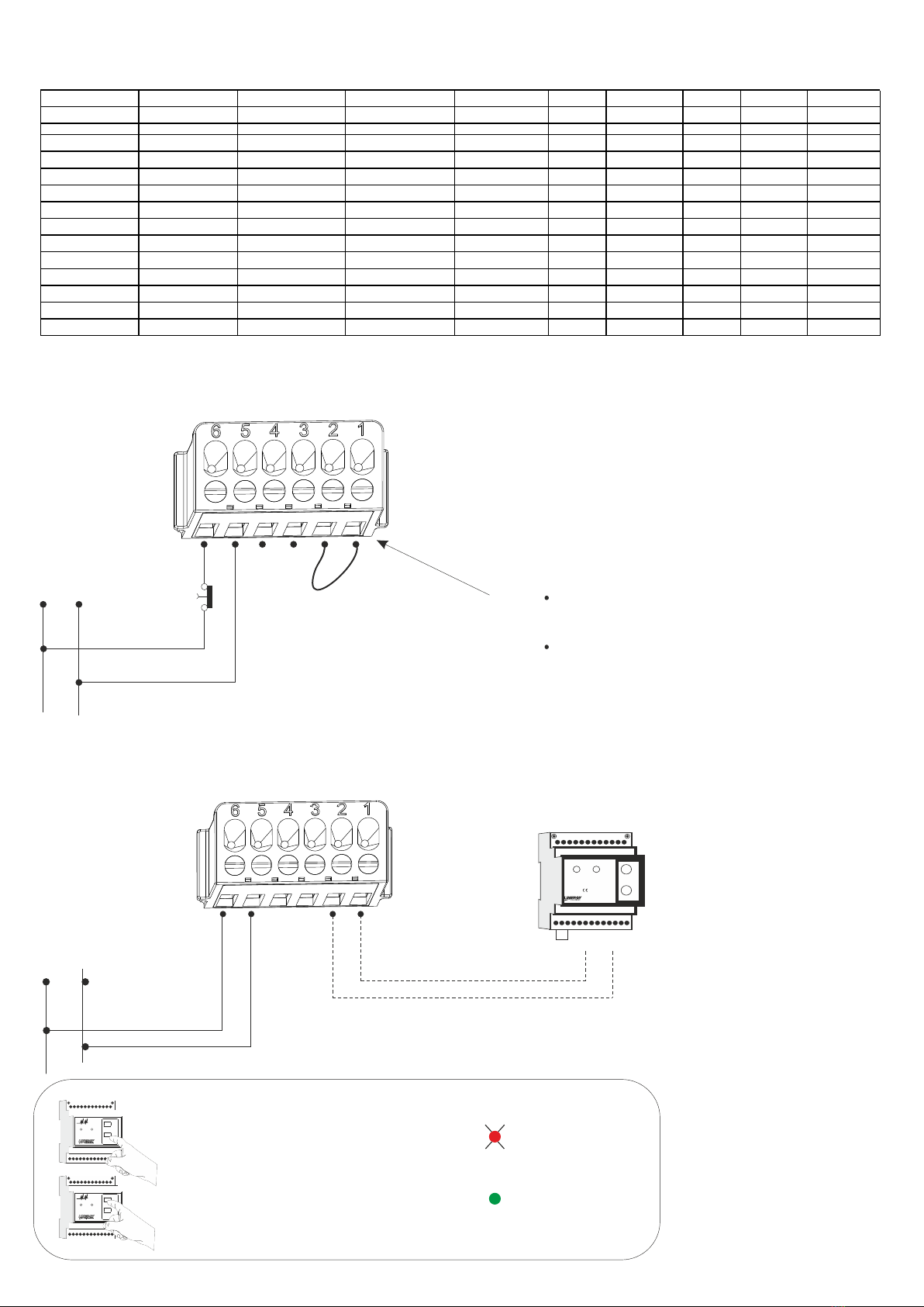
NON PERMANENTE / NON MAINTAINED
230Vac
50-60Hz
SE
- NON PERMANENTE (SE) /NON MAINTAINED
L N INTERRUTTORE
ESTERNO
EXTERNAL
TEST BUTTON
N.B.
Mai collegare la tensione di rete sui morsetti
A-B, la scheda elettronica si danneggia.
A-B Interruttore di inibizione, chiuderlo con un ponte
a filo per abilitare l’emergenza.
SE SA B A
CONFIGURAZIONE DEL PRODOTTO PER L’UTILIZZO DEL COMMANDER:
HOW TO CONFIGURE THE PRODUCT FOR THE USE WITH COMMANDER:
Collegare il Commander ai morsetti A e B della Evolution Led (rispettare la polarità).
Tenere premuto Commander OFF per 11 secondi circa. Tutti i prodotti sono ora in modalità INIBIZIONE.
Tenere premuto Commander ON per 11 secondi circa. Tutti i prodotti sono ora in modalità REST MODE.
Se è necessario ritornare in modalità INIBIZIONE tenere premuto Commander OFF per 11 secondi circa.
Connect the Commander to the A and B terminals of Evolution Led (respect the polarity).
Keep pushed Commander OFF for about 11 seconds. Now all the products are in the INHIBITION mode.
Keep pushed Commander ON for about 11 seconds. Now all the products are in the REST MODE.
If it is necessary to go back to the INHIBITION mode, keep pushed Commander OFF for about 11 seconds.
N.B. Dovendo collegare insieme i morsetti A
e B di diversi prodotti evitare di collegare il
morsetto A di qualche prodotto col morsetto
B di altri prodotti.
N.B. When connecting together the A and B
terminals of many products avoid
connecting The A terminal of some
products with the B terminal of some other
products.
COD. IP42
ENERGY TEST
COD. IP65
ENERGY TEST
COD. IP42
SPY SYSTEM
COD. IP65
SPY SYSTEM
POTENZA
DELLA FONTE
LUMINOSA A LED
AUTONOMIA
DURATION
FLUX
SE(lm)
BATTERIA
BATTERY
RICARICA
RECHARGE
FIGURA
FIGURE
LED POWER
EL 06 N 10 E B R T ES 06 N 10 E B R T EL 06 N 10 E B R C ES 06 N 10 E B R C 768mW 1h 43 NiCd 6V 0,6Ah 12h Fig.4-6
EL 06 N 30 E B R T ES 06 N 30 E B R T EL 06 N 30 E B R C ES 06 N 30 E B R C 768mW 3h 44 NiCd 6V 0,6Ah 12h Fig.4-6
EL 08 N 10 E B R T ES 08 N 10 E B R T EL 08 N 10 E B R C ES 08 N 10 E B R C 1024mW 1h 64 NiCd 6V 0,6Ah 12h Fig.4-6
EL 08 N 30 E B R T ES 08 N 30 E B R T EL 08 N 30 E B R C ES 08 N 30 E B R C 1024mW 3h 64 NiCd 6V 0,8Ah 12h Fig.4-6
EL 11 N 10 E B R T ES 11 N 10 E B R T EL 11 N 10 E B R C ES 11 N 10 E B R C 1280mW 1h 111 NiCd 6V 0,6Ah 12h Fig.4-6
EL 11 N 30 E B R T ES 11 N 30 E B R T EL 11 N 30 E B R C ES 11 N 30 E B R C 1280mW 3h 112 NiCd 6V 1,3Ah 12h Fig.4-6
EL 18 N 10 E B R T ES 18 N 10 E B R T EL 18 N 10 E B R C ES 18 N 10 E B R C 2304W 1h 129 NiCd 6V 0,8Ah 12h Fig.4-6
EL 18 N 30 E B R T ES 18 N 30 E B R T EL 18 N 30 E B R C ES 18 N 30 E B R C 2304W 3h 132 NiCd 6V 1,8Ah 12h Fig.4-6
EL 24 N 10 E B R T ES 24 N 10 E B R T EL 24 N 10 E B R C ES 24 N 10 E B R C 3840mW 1h 244 NiCd 6V 1,3Ah 12h Fig.4-6
EL 24 N 30 E B R T ES 24 N 30 E B R T EL 24 N 30 E B R C ES 24 N 30 E B R C 3840mW 3h 249 NiCd 6V 2,5Ah 12h Fig.4-6
ENERGY TEST ENERGY TEST SPY SYSTEM SPY SYSTEM ASSORBIMENTO N.LED AUTONOMIA TIPO FLUSSO SE BATTERIA
CODE IP42 CODE IP65 CODE IP42 CODE IP65 ABSORPTION DURATION TYPE FLUX NM BATTERY
EL08N10EBRT ES08N10EBRT EL08N10EBRC ES08N10EBRC 0,9 10 LED 1h SE 185 Ni-Cd 6V 0,6Ah
EL08N30EBRT ES08N30EBRT EL08N30EBRC ES08N30EBRC 1,5 10 LED 3h SE 180 Ni-Cd 6V 1,3Ah
EL11N10EBRT ES11N10EBRT EL11N10EBRC ES11N10EBRC 1,2 10 LED 1h SE 205 Ni-Cd 6V 0,8Ah
EL11N30EBRT ES11N30EBRT EL11N30EBRC ES11N30EBRC 1,9 10 LED 3h SE 185 Ni-Cd 6V 1,8Ah
EL18N10EBRT ES18N10EBRT EL18N10EBRC ES18N10EBRC 1,6 20 LED 1h SE 415 Ni-Cd 6V 1,3Ah
EL18N30EBRT ES18N30EBRT EL18N30EBRC ES18N30EBRC 2,6 20 LED 3h SE 295 Ni-Cd 6V 2,5Ah
EL24N10EBRT ES24N10EBRT EL24N10EBRC ES24N10EBRC 1,9 40 LED 1h SE 680 Ni-Cd 6V 1,8Ah
EL24N30EBRT ES24N30EBRT EL24N30EBRC ES24N30EBRC 3,3 40 LED 3h SE 680 Ni-MH 6V 4Ah
EL24N10EBRT-HH ES24N10EBRT-HH EL24N10EBRC-HH ES24N10EBRC-HH 2,9 40 LED 1h SE 1300 Ni-MH 6V 3,3Ah
EL24N10EBRT-H ES24N10EBRT-H EL24N10EBRC-H ES24N10EBRC-H 2,6 40 LED 1h SE 870 Ni-Cd 6V 2,5Ah
EL24N13EBRT-HH ES24N13EBRT-HH EL24N13EBRC-HH ES24N13EBRC-HH 3,3 40 LED 1,5h SE 1300 Ni-MH 6V 4Ah
EL24N20EBRT-H ES24N20EBRT-H EL24N20EBRC-H ES24N20EBRC-H 3,3 40 LED 2h SE 870 Ni-MH 6V 4Ah
CO
COCO
ANDER
ANDERANDER
ACAC
POWERPOWER
AC
POWER
EMERGENCYEMERGENCY
STATESTATE
EMERGENCY
STATE
EMERGENCYEMERGENCY
MODE MODE
EMERGENCY
MODE
ONONON
OFFOFFOFF
CO
COCO
ANDER
ANDERANDER
AC
POWER
EMERGENCY
STATE
EMERGENCY
MODE
ON
OFF
CO
COCO
ANDER
ANDERANDER
ACAC
POWERPOWER
AC
POWER
EMERGENCYEMERGENCY
STATESTATE
EMERGENCY
STATE
EMERGENCYEMERGENCY
MODE MODE
EMERGENCY
MODE
ONONON
OFFOFFOFF
CO
COCO
ANDER
ANDERANDER
AC
POWER
EMERGENCY
STATE
EMERGENCY
MODE
ON
OFF
- Tenere premuto Commander OFF per 11 secondi
PRODOTTI IN INIBIZIONE
- Tenere premuto Commander ON per 11 secondi
PRODOTTI IN REST MODE
- Press Commander Off for 11 seconds
FITTINGS IN INHIBITION MODE
- Press Commander ON for 11 seconds
FITTINGS IN REST MODE
Led rosso
lampeggiante lento
Red Led
slow flashing
Led verde
acceso fisso
Green Led
light on
sugli apparecchi - on the fittings
*n.b. qualora ci fossero altri prodotti già’ configurati per il Commander,
sulla stessa linea potrebbe iniziare un test funzionale di circa 20 secondi.
* N.B. If there were other products already configured for the Commander
on the same line, a functional test of about 20 seconds could start.
230Vac
50-60Hz
SE
- NON PERMANENTE SE / NON MAINTAINED
NOTE:
Non collegare il ponticello A-B se si utilizza il Commander.
Do not short the A B terminals if you are using the Commander.
- REST MODE CON COMMANDER / REST MODE WITH COMANNDER

- PERMANENTE (SA) / MAINTAINED
230Vac
50Hz 230Vac
50Hz
SE SA
L N
L N
INTERRUTTORE
ESTERNO
EXTERNAL
TEST BUTTON
N.B.
Never connect the main supply to the A-B pins.
The electronic circuit breaks down.
A-B Inhibition switch, close it with a short wire
to enable the emergency.
SE SA B A
- PERMANENTE SA / MAINTAINED
L N
L N
SE SA B A
230Vac
50-60Hz
B
A
230Vac
COMMANDER
Presenza
RETE
Abilitazione
Emergenza
COMMANDER
ON
OFF
A
B
I
L
I
T
A
Z
I
O
N
E
REST MODE
(OPTIONAL)
230Vac
50-60Hz
SE SA
NOTE:
Non collegare il ponticello A-B se si utilizza il Commander.
Do not short the A B terminals if you are using the Commander.
TABELLA MODELLI / TABLE MODELS
PERMANENTE / MAINTAINED
VERDE ACCESO FISSO / GREEN ON, NOT FLASHING PRESENZA RETE, NESSUNA ANOMALIA / MAINS SUPPLY ON, NO WARNING
TEST IN CORSO / TEST IN PROGRESS
TEST DISABILITATI - LAMPADA INIBITA* / TEST DISABLED - LUMINAIRE INHIBITED*
GUASTO BATTERIA / BATTERY FAULT
LAMPADA GUASTA / BATTERIA NON CONNESSA - LUMINAIRE FAULT - BATTERY NOT CONNECT
VERDE LAMPEGGIANTE / GREEN FLASHING
ROSSO LAMPEGGIANTE LENTO / RED SLOW FLASHING
ROSSO LAMPEGGIANTE VELOCE / RED SLOW FLASHING
ROSSO ACCESO FISSO / RED ON, NOT FLASHING
SIGNIFICATO / LED MEANING
SEGNALAZIONI LED / LED SIGNALLING
CONDIZIONI DI GARANZIA / WARRANTY CONDITION
La garanzia sugli apparecchi di emergenza è di 5 anni dalla data di vendita. La
garanzia decade se il prodotto è stato manomesso o riparato da personale non
autorizzato LINERGY.
The warranty on the emergency luminaire is 5 years from the sales date. The
warranty voids if the product has been mishandled or repaired by personnel not
authorized by LINERGY.
Il cassonetto barrato sull’apparecchio specifica che il prodotto deve
essere consegnato ai centri di raccolta autorizzati per un corretto
smaltimento. Rivolgersi all’ufficio competente del proprio ente locale per
informazioni sulla raccolta e sui termini di legge.
The crossed out waste bin symbol indicates that the product should be
taken to an authorized waste collection centre which can dispose of it
properly. For information on waste collection centres and on current
waste disposal legislation, please contact your local waste disposal
authority.
LE CORNICI SE NON VENGONO USATE, POSSONO ESSERE SMALTITE
PRESSO I CENTRI DI RACCOLTA DIFFERENZIATA DELLA PLASTICA DEL
PROPRIO ENTE LOCALE
FOR WHAT CONCERNS THE FRAME THAT YOU ARE NOT USING, IT
SHOULD BE DISPOSED OF AT THE RECYCLING CENTER OF YOUR CITY
ENERGY TEST ENERGY TEST SPY SYSTEM SPY SYSTEM ASSORBIMENTO N.LED AUTONOMIA TIPO FLUSSO SE FLUSSO SA BATTERIA
CODE IP42 CODE IP65 CODE IP42 CODE IP65 ABSORPTION DURATION TYPE FLUX NM FLUX M BATTERY
EL08N10ABRT ES08N10ABRT EL08N10ABRC ES08N10ABRC 4,2 10 LED 1h SA 185 185 Ni-Cd 6V 0,6Ah
EL08N30ABRT ES08N30ABRT EL08N30ABRC ES08N30ABRC 4 10 LED 3h SA 180 180 Ni-Cd 6V 1,3Ah
EL11N10ABRT ES11N10ABRT EL11N10ABRC ES11N10ABRC 5,2 10 LED 1h SA 205 205 Ni-Cd 6V 0,8Ah
EL11N30ABRT ES11N30ABRT EL11N30ABRC ES11N30ABRC 4,7 10 LED 3h SA 185 185 Ni-Cd 6V 1,8Ah
EL18N10ABRT ES18N10ABRT EL18N10ABRC ES18N10ABRC 8,3 20 LED 1h SA 415 415 Ni-Cd 6V 1,3Ah
EL18N30ABRT ES18N30ABRT EL18N30ABRC ES18N30ABRC 6,5 20 LED 3h SA 295 295 Ni-Cd 6V 2,5Ah
EL24N10ABRT ES24N10ABRT EL24N10ABRC ES24N10ABRC 9,5 40 LED 1h SA 680 680 Ni-Cd 6V 1,8Ah
EL24N30ABRT ES24N30ABRT EL24N30ABRC ES24N30ABRC 10,7 40 LED 3h SA 680 680 Ni-MH 6V 4Ah
Green Led ON in presence of the 230Vac = Battery connected
Led Rosso Acceso in presenza di rete 230Vac = Batteria scollegata
Led Verde Acceso in presenza di rete 230Vac = Batteria collegata
Red Led ON in presence of the 230Vac = Battery disconnected
CONNETTERE LA BATTERIA AL CIRCUITO ELETTRONICO / CONNECT THE BATTERY TO THE CIRCUIT
J2
SULLA SCHEDA ELETTRONICA
ON THE ELECTRONIC BOARD
BATTERIA - BATTERY
BATTERY STATUS
Led rosso acceso fisso
in caso di batteria disconnessa
Red led constant ON
in case of disconnected battery

LINERGY S.R.L. - via A. De Gasperi 9 - Acquaviva Picena (AP) - ITALY - tel.0735.5974 - fax 0735.597474 - www.linergy.it - info@linergy.it - ISTEVOLED-ET - Ver. 2.6
CENTRALIZZATE SPY SYSTEM / SPY SYSTEM CENTRALIZED
- NON PERMANENTE/NON MAINTAINED
MODELLI / MODELS EBRC
- PERMANENTE / MAINTAINED
MODELLI / MODELS ABRC
The Bus:
The bus used for the Spy System must have
a bipolar, twisted and shielded cable (min.
2x0,5 mm²). The connection is a Point to
Point type, i.e. input and output of the
fixtures must be, as shown in fig. no. 2. The
connection must be done respecting the
polarity of "A" and "B" both on the lamps and
on the plant.
Respect the polarity of the Bus.
Attention:
For a correct operation of the whole plant it is necessary to
terminate the bus, inserting the resistors supplied with the
central in order to end the lines of each series.
If at the end there is repeater, it is necessary to terminate it
as if it were a fixture, the strip is between the terminal board
of Bus In and Bus Out.
Bus TerminationTerminazione del Bus /
Il Bus:
Il Bus che deve essere utilizzato per lo Spy
System deve avere un cavo bi-polare (minimo
2
2x0,50mm ) twistato e schermato. La tipologia
di connessione deve essere Punto Punto,
ossia si deve entrare ed uscire da ogni
plafoniera come è visibile negli schemi a lato. Il
collegamento deve essere fatto rispettando le
polarità di “A” e “B” sia sulle lampade che sulla
centrale.
B
B
A
A
Rispettare la polarità del Bus.
Avvertenze:
Per un corretto funzionamento di tutto l’impianto occorre
Terminare il Bus inserendo le resistenza in dotazione con
la centrale, di tutte le lampade che si trovano alla fine delle
linee di ogni serie.
Nel caso in cui l’ultimo apparecchio sia un ripetitore occorre
terminarlo come se fosse una plafoniera, lo strip si trova tra
le morsettiere di Bus IN e Bus OUT.
ATTENZIONE
La sorgente luminosa a LED non è sostituibile.
WARNING
LED source is not replaceable.
L N
L N
L N
SE SA B A
SE SA B A
Fig. 6
230Vac
50-60Hz
SE
B
A
Fig .7
230Vac
50-60Hz
B
A
230Vac
50-60Hz
SE
SA
/ Max 128 luminaires on this Bus Line. 500m Max Cable Extension..
/ Max 128 luminaires on this Bus Line. 500m Max Cable Extension.
/ Max 128 luminaires on this Bus Line. 500m Max Cable Extension..Massimo 128 Plafoniere su questa linea Bus. Lunghezza massima del Cavo 500m
Massimo 128 Plafoniere su questa linea Bus. Lunghezza massima del Cavo 500m
Massimo 128 Plafoniere su questa linea Bus. Lunghezza massima del Cavo 500m
Massimo 128 Plafoniere su questa linea Bus. Lunghezza massima del Cavo 500m
Massimo 128 Plafoniere su questa linea Bus. Lunghezza massima del Cavo 500m
Massimo 128 Plafoniere su questa linea Bus. Lunghezza massima del Cavo 500m
Bus Termination
Bus Termination
Bus Termination
on the Repeater.
Rete di Alimentazione 230Vac
L
N
Massimo 128 Plafoniere su questa linea Bus.
Lunghezza massima del Cavo 500mt.
Plafoniere Palazzina Uffici / Luminaires Offices buildings
Plafoniere Palazzina Officine / Luminaires workshops buildings
Plafoniere Locali Tecnici / Luminaires Technical locals
Plafoniere Locali Tecnici 2 / Luminaires Technical locals 2
Terminare il Bus
sul Repeater.
T
T
T
Collegamento alla centrale Spy System con Ripetitori Bus a 4 e 2 Vie / Connection to the SPy System using to 2 or 4 - ways repeaters.
Linea Bus 2
Plafoniere al Piano Terra / Downstairs
Plafoniere al Piano Seminterrato / Basement
Plafoniere al Primo Piano / First Floor
Plafoniere al Secondo Piano / Second Floor
Plafoniere al Terzo Piano / Third Floor
Plafoniere al Quarto Piano / Fourth Floor
Terminare il Bus
su quest’ultima
Plafoniera.
Terminare il Bus
su quest’ultima
Plafoniera.
Terminare il Bus
su quest’ultima
Plafoniera.
Terminare il Bus
su quest’ultima
Plafoniera.
Terminare il Bus
su quest’ultima
Plafoniera.
T
T
T
T
Fig. 8
Linea Bus 1
BUS 4
BUS 3
BUS 2
BUS 1
SS-REP/4
IN OUT
BUS MASTER
SS-REP/2
IN OUT
BUS MASTER
BUS 2
BUS 1
T
This manual suits for next models
1
Other Linergy Test Equipment manuals


