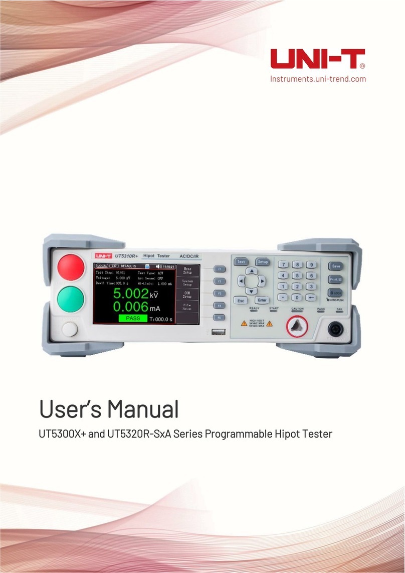
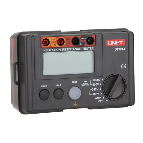
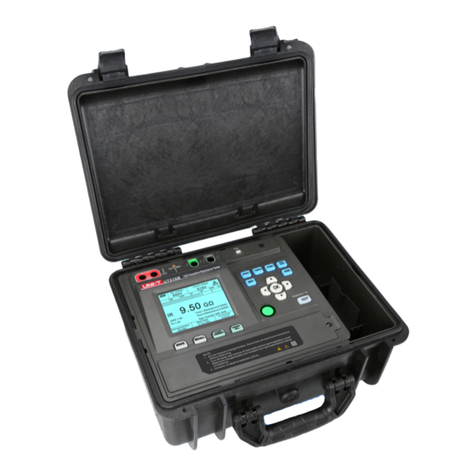
manuals.online logo
Brands
  1. Home
  2. •
  3. Brands
  4. •
  5. Unit
  6. •
  7. Test Equipment
  8. •
  9. Unit UTD2000CEX+ Series User manual

Unit UTD2000CEX+ Series User manual

This manual suits for next models

10

Other Unit Test Equipment manuals

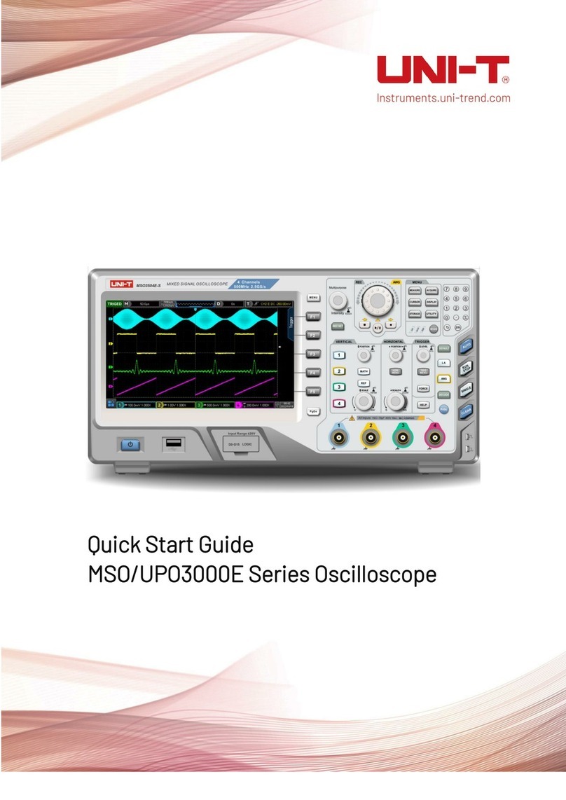
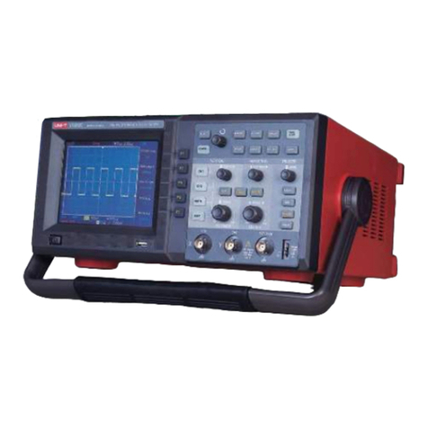
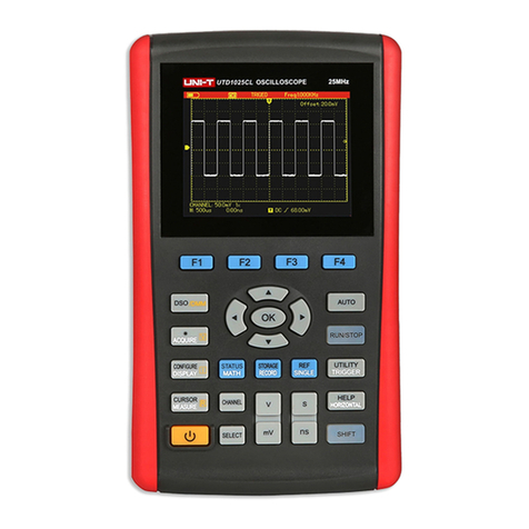
Unit MSO Series User manual

Unit

Unit MSO Series User manual

Unit UT526 User manual

Unit

Unit UT526 User manual

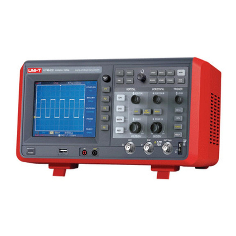
Unit UT 4000 Series User manual

Unit

Unit UT 4000 Series User manual

Unit UPO1000CS Series User manual

Unit

Unit UPO1000CS Series User manual

Unit UT311A User manual

Unit

Unit UT311A User manual

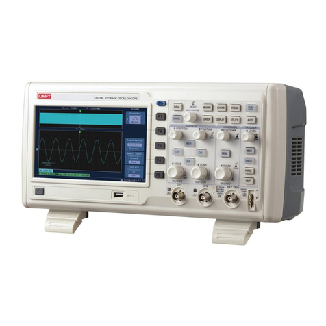
Unit UTD2000CEX-II Series User manual

Unit

Unit UTD2000CEX-II Series User manual

Unit UT890D User manual

Unit

Unit UT890D User manual

Unit MSO/UPO2000 Series Owner's manual

Unit

Unit MSO/UPO2000 Series Owner's manual

Unit UTD1000L Series User manual

Unit

Unit UTD1000L Series User manual

Unit UT5300X+ Series User manual

Unit

Unit UT5300X+ Series User manual

Unit UPO1000 Series User manual

Unit

Unit UPO1000 Series User manual

Unit UTG1000X Series Owner's manual

Unit

Unit UTG1000X Series Owner's manual

Unit utd2000 User manual

Unit

Unit utd2000 User manual

Unit UT712 User manual

Unit

Unit UT712 User manual

Unit UT276A User manual

Unit

Unit UT276A User manual

Unit UPO1000 Series User manual

Unit

Unit UPO1000 Series User manual

Unit UPO2102 User manual

Unit

Unit UPO2102 User manual

Unit UPO2000CS Series User manual

Unit

Unit UPO2000CS Series User manual

Unit UPO1000CS Series User manual

Unit

Unit UPO1000CS Series User manual

Unit UT361 User manual

Unit

Unit UT361 User manual

Unit UPO2000E Series User manual

Unit

Unit UPO2000E Series User manual

Unit UT5583 User manual

Unit

Unit UT5583 User manual

Unit UT513A User manual

Unit

Unit UT513A User manual

Unit UT3200+ Series User manual

Unit

Unit UT3200+ Series User manual

Popular Test Equipment manuals by other brands

Ambit P.F. Series instruction manual

Ambit

Ambit P.F. Series instruction manual

Megger BMM500 Series user guide

Megger

Megger BMM500 Series user guide

RJG Lynx Sensor Tester operating instructions

RJG

RJG Lynx Sensor Tester operating instructions

Mark-10 TT02 Series user guide

Mark-10

Mark-10 TT02 Series user guide

Martel 3001 Operator's manual

Martel

Martel 3001 Operator's manual

ElproSys DiagProg4 instruction manual

ElproSys

ElproSys DiagProg4 instruction manual

Redtech TRAILERteck T05 user manual

Redtech

Redtech TRAILERteck T05 user manual

Venmar AVS Constructo 1.0 HRV user guide

Venmar

Venmar AVS Constructo 1.0 HRV user guide

Test Instrument Solutions SafetyPAT operating manual

Test Instrument Solutions

Test Instrument Solutions SafetyPAT operating manual

Hanna Instruments HI 38078 instruction manual

Hanna Instruments

Hanna Instruments HI 38078 instruction manual

Kistler 5495C Series instruction manual

Kistler

Kistler 5495C Series instruction manual

Waygate Technologies DM5E Basic quick start guide

Waygate Technologies

Waygate Technologies DM5E Basic quick start guide

StoneL DeviceNet CK464002A manual

StoneL

StoneL DeviceNet CK464002A manual

Seica RAPID 220 Site preparation guide

Seica

Seica RAPID 220 Site preparation guide

Kingfisher KI7400 Series Training manual

Kingfisher

Kingfisher KI7400 Series Training manual

Kurth Electronic CCTS-03 operating manual

Kurth Electronic

Kurth Electronic CCTS-03 operating manual

SMART KANAAD SBT XTREME 3G Series user manual

SMART

SMART KANAAD SBT XTREME 3G Series user manual

Agilent Technologies BERT Serial Getting started

Agilent Technologies

Agilent Technologies BERT Serial Getting started

manuals.online logo
manuals.online logoBrands
  • About & Mission
  • Contact us
  • Privacy Policy
  • Terms and Conditions

Copyright 2025 Manuals.Online. All Rights Reserved.

UTD2000 Series
Digital Oscilloscope
User Manual
www.uni-trend.com.cn
UTD2000 Series User Manual
2
Preface
Dear custumer,
Thank you for choosing this UNI-T device. In order to safely and correctly use this
instrument .please read this manual thoroughly, especially the Safety Notes part. After
reading this manual, it is recommended to keep the manual at an easily accessible place,
preferably close to the device, for future reference.
Copyright and Declaration
Copyright Information
UNl-T Uni-Trend Technology (China) Co., Ltd. All rights reserved.
Trademark Information
UNI-T is the registered trademark of Uni-Trend Technology (China) Co., Ltd.
Document Version
UTD2000 -20220104-REV.5
Statement
 UNI-T products are protected by patent rights in China and other countries, including
issued and pending patents.
 UNI-T reserves the rights to any product specification and pricing changes.
 UNI-T reserves all rights. Licensed software products are properties of Uni-Trend and
its subsidiaries or suppliers, which are protected by national copyright laws and
international treaty provisions.
Information in this manual supercedes all previously published versions.
UTD2000 Series User Manual
3
If this product is sold or assigned by the original purchaser to a third party within three
years of purchase, the new owner should note that warranty is available for a period of
three years from the day the original purchaser acquired the product from Uni-T or an
authorized dealer. The probe, other accessories and fuses are not covered by warranty.
If any genuine defect is found during the valid warranty period, Uni-T has the option to
repair the defective product without any charge for parts or labor, or replace it with another
product (at the discretion of Uni-T). Uni-T may use parts, modules and replacement
products that are brand new or repaired to a good-as-new standard. All old parts, modules
and products that are removed during replacement become properties of Uni-T.
In this User Manual, “customer” means an individual or entity vested with the rights
hereunder. To enjoy the warranty service, the “customer” must report any defect to Uni-T
during the valid warranty period and make appropriate arrangement to allow servicing. The
customer should pack the defective product in a container and deliver it to a maintenance
centre specified by Uni-T. The customer should also prepay all freight cost and provide a
copy of the original sales receipt issued to the original purchaser. If the product is to be
delivered to an address within the country where the maintenance centre operates, Uni-T
shall pay the cost of returning the product to the destination, all freight, custom duty, tax
and other costs will be paid by the customer.
This warranty shall not apply to any defects or damages caused by accidental, machine
parts’ wear and tear, improper use, and improper or lack of maintenance. UNI-T under the
provisions of this warranty has no obligation to provide the following services:
a) Any repair damage caused by the installation, repair, or maintenance of the product by
non UNI-T service representatives.
b) Any repair damage caused by improper use or connection to an incompatible device.
c) Any damage or malfunction caused by the use of a power source that does not conform
to the requirements of this manual.
d) Any maintenance on altered or integrated products (if such alteration or integration leads
to an increase in time or difficulty of product maintenance).
This warranty written by UNI-T for this product, and it is used to substitute any other
express or implied warranties. UNI-T and its distributors do not offer any implied warranties
for merchantability or applicability purposes.
For violation of this guarantee, UNI-T is responsible for the repair or replacement of
defective products is the only remedy available to customers. Regardless of whether UNI-
T and its distributors are informed that any indirect, special, incidental, or consequential
damage may occur, UNI-T and its distributors shall not be responsible for any of the
damages.
UTD2000 Series User Manual
4
General Safety Overview
This instrument strictly complies with the safety requirements for electronic measuring
instrument IEC 61010-1 safety standard during design and manufacturing. Please
understand the following safety preventative measures, to avoid personal injury, and to
prevent damage to the product or any connected products. To avoid possible dangers, be
sure to use this product in accordance with the regulations. If the equipment is used in a
manner not specified by manufacturer, the protection provided by the equipment may be
impaired
 Only trained personnel can perform the maintenance program.
 Avoid fire and personal injury:
 Use the correct power line: Only use the dedicated UNI-T power supply appointed to
the local region or country for this product. The rating shall not be lower than the rating
requirements.
Mains supply cord set specification
Applicable area Type Rating Standard
For EU
Plug AC 250V, 10A
IEC 60779
Cord 3X0.75mm², 300V,105°C
Connector AC 250V, 10A
For US and CAN
Plug AC 125V,10A
UL 498
Cord 3X18AWG, 300V,105°C
Connector AC 125V,10A
 Correct Plug: Don't plug when the probe or test wire is connected to the voltage source.
 Ground the product: This product is grounded through the power supply ground wire.
To avoid electric shock, grounding conductors must be connected to the ground.
Please be sure that the product is properly grounded before connecting to the input or
output of the product. Safety considerations, When measuring dangerous voltage,
wear protective equipment, such as insulating gloves, and keep away from others.
 Correct connection of oscilloscope probe: Ensure that the probe ground and ground
potential are correctly connected. Do not connect ground wire to high voltage. Must
use impedance not less than 1 MΩ Probe.
 Check all terminal ratings: To avoid fire and the large current charge, please check all
the ratings and the marks on the product. Please also refer to the product manual for
details on the ratings before connecting to the product. Do not use beyond the range.
 Do not open the case cover or front panel during operation.
 Only use fuses with ratings listed in the technical index.
 Avoid circuit exposure: Do not touch exposed connectors and components after power
is connected.
UTD2000 Series User Manual
5
 Do not operate the product if you suspect it is faulty, and please contact UNI-T
authorized service personnel for inspection. Any maintenance, adjustment, or
replacement of parts must be performed by UNI-T authorized maintenance personnel.
 Instructions not to position the equipment so that it is difficult to operate the
disconnecting device
 Maintain proper ventilation.
 Do not used to measure MAINS CIRCUIT.
 Before each use verify tester operation by measuring a known voltage.
 Please do not operate the product in humid conditions.
 Please do not operate in inflammable and explosive environment.
 Please keep the product surface clean and dry
Radio frequency magnetic field:
CS: The product was tested per EN 61000-4-6, interference signal amplitude is 3V,
frequency is beween 150kHz to 80MHz. The waveform will be affected with interference
signal, and return to normal after removing it.
RS: The product was tested per EN 61000-4-3,interference signal is under below situation:
1、Amplitude=3V, Frequency is beween 80MHz to 1GHz and 1.4GHz to 2GHz;2、
Amplitude=1V, Frequency is beween 2GHz to 2.7GHz; The waveform will be affected with
interference signal, and return to normal after removing it.
UTD2000 Series User Manual
6
Safety Terms and Symbols
The following terms may appear in this manual:
Warning: The conditions and behaviors may endanger life.
Note: The conditions and behaviors may cause damage to the product and other
properties.
The following terms may appear on the product:
Danger: Performing this operation may cause immediate damage to the operator.
Warning: This operation may cause potential damage to the operator.
Note: This operation may cause damage to the product and devices connected to the
product.
The following symbols may appear on the product:
Symbol Description
Direct current
Alternating current
Earth (ground) TERMINAL
PROTECTIVE CONDUCTOR TERMINAL
Caution, possibility of electric shock
Warning or Caution
Frame or chassis TERMINAL
Comply with European Union standards
Conforms to UL STD 61010-1, 61010-2-030, Certified to CSA
STD C22.2 No. 61010-1, 61010-2-030.
Do not place equipment and its accessories in the trash. Items
must be properly disposed of in accordance with local
regulations.
UTD2000 Series User Manual
7
Preface
The Manual introduces information related to operation of digital storage oscilloscope of
UTD2000 series user manual. The Manual comprises the following chapters:
Chapter 1 Introduction Guide
Chapter 2 Vertical channel setting
Chapter 3 Horizontal system setting
Chapter 4 Trigger system setting
Chapter 5 Sampling system setting
Chapter 6 Display system setting
Chapter 7 Automatic measurement
Chapter 8 Cursor measurement
Chapter 9 Storage and callback
Chapter 10 Auxiliary function setting
Chapter 11 Other function keys
Chapter 12 Applicaion example
Chapter 13 System prompt and troubleshooting
Chapter 14 Technical specification
Chapter 15 Appendix
UTD2000 Series Digital Storage Oscilloscope contains the following 9 models:
Series Model Band Width Sampling Rate
UTD2000
UTD2052CL+ 50MHz 500MS/s
UTD2072CL 70MHz 500MS/s
UTD2102CL+ 100MHz 500MS/s
UTD2102CL PRO 100MHz 500MS/s
UTD2152CL 150MHz 500MS/s
UTD2052CEX+ 50MHz 1GS/s
UTD2102CEX+ 100MHz 1GS/s
UTD2152CEX 150MHz 1GS/s
UTD2202CEX+ 200MHz 1GS/s
UTD2000 series provide the users with front panels with simple operation and clear
functions to perform all the basic operations. Scale and position knobs of each channel
provide visual operations that are suitable for user habits as the traditional instrument.
Users may be able to master it without spending plenty of time learning and understanding
operations of any UTD2000 series DSO. In order to accelerate adjustment and facilitate
measurement, the users can directly press AUTO key and the instrument will then display
applicable waveform and gear position settings.
UTD2000 Series User Manual
8
Apart from easy to use, UTD2000 series DSO also has high performance indexes and
powerful functions required for faster completion of measurement tasks. User can observe
faster signals on UTD200 series DSO by high-speed real time sampling and equivalent
sampling. Clear LCD and mathematical operation functions make it easier for users to
observe and analyze signal problems in a faster and clearer way.
From the following parameter features, you can understand how this series of DSO can
satisfy your measurement requirements.
 Two analog channels.
 High resolution LCD display 800×480 resolution.
 Support plug and play USB storage equipment or be capable of communicating with
computer via USB storage equipment.
 Automatic waveform and state settings
 Waveform saving and replay feature
 Delicate window extension function and precise analysis on waveform details and
overview
 Automatic measurement of 34 waveform parameters
 Automatic cursor tracking measurement function
 Unique functions of waveform recording and playback.
 Built-in FFT software function
 Multi-waveform mathematical operation function (including: addition, subtraction,
multiplication and division)
 Edge, Video, Slope, Pulse width, Alternating trigger and other functions
 Multi-language menu selection
 Help Information in Mutil-language.
UTD2000 Series User Manual
9
Contents
Guaranty and Declaration ................................................................................................. 2
General Safety Overview .................................................................................................. 4
Safety Terms and Symbols ............................................................................................... 6
Preface. ........................................................................................................................... 7
Contents ............................................................................................................................ 9
Chapter I Introductions ................................................................................................. 11
1.1 General Inspection ............................................................................................. 11
1.2 Function Inspection ............................................................................................ 11
1.3 Front and Rear Panel ......................................................................................... 12
1.4 Display ............................................................................................................... 13
1.5 Automatic Settings of Waveform Display ........................................................... 14
1.6 Introduction to The Vertical System.................................................................... 14
1.7 Introduction to The Horizontal System ............................................................... 15
1.8 Introduction to The Trigger System .................................................................... 16
Chapter II Vertical System ............................................................................................ 17
2.1 Setting coupling channel .................................................................................... 17
2.2 Setting channel bandwidth Limited .................................................................... 18
2.3 Setting probe Rate ............................................................................................. 19
2.4 Vertical Volts/Div adjustment setting .................................................................. 20
2.5 Settings of waveform inverting ........................................................................... 20
2.6 Mathematical operation function ........................................................................ 21
2.7 FFT spectral analysis ......................................................................................... 22
Chapter III Horizontal System ....................................................................................... 24
3.1 Horizontal control ............................................................................................... 24
3.2 Explanation of nouns ......................................................................................... 24
3.3 Window extension .............................................................................................. 25
3.4 Trigger hold-off time adjustment ......................................................................... 25
Chapter IV Trigger System ........................................................................................... 27
4.1 Edge trigger ....................................................................................................... 27
4.2 Pulse width trigger ............................................................................................. 28
4.3 Video trigger ....................................................................................................... 30
4.4 Alternating trigger ............................................................................................... 31
4.6 Explanation of nouns ......................................................................................... 33
Chapter V Acquire System ........................................................................................... 34
Chapter VI Display System ........................................................................................... 37
6.1 XY Mode ............................................................................................................ 37
Chapter VII Measurement Parameters ......................................................................... 38
7.1 Measurement Menu ........................................................................................... 38
UTD2000 Series User Manual
10
7.2 Voltage Parameter ............................................................................................. 38
7.3 Time parameter .................................................................................................. 39
Chapter VIII Cursor Measurement ................................................................................ 41
Chapter IX Storage and Load System .......................................................................... 41
9.1 Setup storage and load ...................................................................................... 43
9.2 Waveform storage and load ............................................................................... 44
9.3 Bit map storage and load ................................................................................... 45
9.4 Screen copy ....................................................................................................... 45
Chapter X Utility System ............................................................................................... 46
10.1 Pass/Fail .......................................................................................................... 47
10.2 Recorder .......................................................................................................... 48
Chapter XI Other funtion botton .................................................................................... 50
11.1 AUTO ............................................................................................................... 50
11.2 RUN/STOP ....................................................................................................... 50
11.3 Help Menu ........................................................................................................ 51
11.4 Upgrade program ............................................................................................. 51
Chapter XII Applicaion example ................................................................................... 52
Example 1: Measuring simple signals ...................................................................... 52
Example 2: Observing the delay caused by a sine wave signal passes through the
circuit ....................................................................................................................... 52
Example 3: Acquiring single signals ......................................................................... 53
Example 4: Reducing random noise of signals ........................................................ 54
Example 5: Using the cursors for measurement ...................................................... 55
Chapter XIII System Prompts and Trouble-shooting .................................................... 57
13.1 Definitions of System Prompts ......................................................................... 57
13.2 Troubleshooting ............................................................................................... 57
Chapter XIV Technical Information ............................................................................... 59
Chapter XV Appendix ................................................................................................... 64
Appendix A Accessories of UTD2000 Series ........................................................... 64
Appendix B Maintenance and Cleaning ................................................................... 64
Appendix C Warranty ............................................................................................... 64
Appendix D Contact Us ............................................................................................ 65