LINET SafetyMonitor Parts list manual

D9U001SW0-0101
Version: 02
Publication date: 2019-06

2/46 D9U001SW0-0101_02
Manufacturer:
LINET spol. s r. o.
Želevčice 5
274 01 Slaný
Czech Republic
Tel.: +420 312 576 111
Fax: +420 312 522 668
E-mail: [email protected]
http://www.linet.cz
SafetyMonitor
LINET® bed monitoring system, bed placement and patient presence on bed
Author: LINET spol. s r. o.
Link: www.linet.cz
D9U001SW0-0101
Version: 02
Publication date: 2019-06
Copyright © LINET spol. s r. o., 2019
Translation © LINET spol. s r. o., 2019
All rights reserved. All trademarks or names are the property of the respective owners. LINET s.r.o. reserves the right to
change the specifi cations at any time without notice. The information contained in this document is presented by LINET®
in an effort to provide accurate and correct information. However, LINET® is not responsible for the consequences of
using this information, patent infringement, or other third party rights arising out of the use of this information.

D9U001SW0-0101_02 3/46
1 Symbols and Defi nitions ................................................................................. 4
1.1 Warning Notices............................................................................................................. 4
1.1.1Types of Warning Notices ........................................................................................... 4
1.1.2 Warning Structure ....................................................................................................... 4
1.2 Instructions..................................................................................................................... 4
1.3 Lists................................................................................................................................ 4
1.4 Product Symbols............................................................................................................ 5
1.5 Identifi cation Labels ....................................................................................................... 6
1.6Acoustic Signalling ......................................................................................................... 6
1.7 Defi nition ........................................................................................................................ 7
1.8 Abbreviations ................................................................................................................. 7
2 Safety Instructions........................................................................................... 8
2.1 Safety Guidelines........................................................................................................... 8
3 Intended Use .................................................................................................... 9
3.1 SafetyMonitor................................................................................................................. 9
3.2 Specifi cations for Use .................................................................................................... 9
3.3 Contraindications ........................................................................................................... 10
3.4Ambient Conditions ........................................................................................................ 10
3.5 Storage Conditions ........................................................................................................ 10
3.6 Supported Beds ............................................................................................................. 10
3.7 Compatible mattress ...................................................................................................... 10
4 System Description ....................................................................................... 11
4.1 User Interface ................................................................................................................ 13
4.2 Localisation Transmitter (Tag) ........................................................................................ 13
4.3 Localisation Receiver..................................................................................................... 13
4.4 Bed Parking Position...................................................................................................... 13
4.5 iBoard Standard (controller integrated in the head siderail)........................................... 14
4.6 iBoard Basic (controller integrated in the head siderail) ................................................ 14
5 Technical Specifi cations ............................................................................... 15
5.1 Technical Requirements on the Part of the Customer.................................................... 15
5.2 Technical Specifi cations................................................................................................. 15
6 Electrical Specifi cations................................................................................ 16
6.1 Electrical Specifi cations ................................................................................................. 16
6.2 Electronic Compatibility.................................................................................................. 16
6.3 Electromagnetic Compatibility........................................................................................ 16
6.3.1 Instructions and Manufacturer’s Declaration – Electromagnetic Radiation................. 17
6.3.2 Instructions and Manufacturer’s Declaration – Electromagnetic Immunity ................. 17
7 Scope of Delivery and Product Variants...................................................... 19
8 Putting into Service ....................................................................................... 19
8.1 SafetyMonitor Installation............................................................................................... 19
8.3 Transporting the Bed...................................................................................................... 20
8.2 Tag Installation ............................................................................................................... 20
9 Conditions of Use .......................................................................................... 21
9.1 SafetyMonitor Status in Case of Power Failure ............................................................ 21
9.2 SafetyMonitor Status in Case of Wi-Fi Connection Failure............................................ 21
10 Using the System......................................................................................... 21
11 Controls ........................................................................................................ 22
11.1 iBoard Standard (Eleganza 5)...................................................................................... 22
11.1.1 Description of Functions Indicated on the Display (Eleganza 5)............................... 24
11.1.2 Description of Bed Adjustable Functions................................................................... 25
11.2 iBoard Basic (Eleganza 4)............................................................................................ 26
11.2.1 Description of Functions Indicated on the Display (Eleganza 4) ............................... 27
11.2.2 Description of Functions Adjustable on the Bed........................................................ 29
12 Bed Exit Monitoring ..................................................................................... 30
12.1 Limits of Bed Exit Monitoring ....................................................................................... 31
13 Sound Signalling ......................................................................................... 31
13.1Alert ............................................................................................................................. 31
13.2 Bed Exit Alarm ............................................................................................................. 31
14 User Interface ............................................................................................... 34
14.1 Control Panel ............................................................................................................... 34
Table of Contents

4/46 D9U001SW0-0101_02
1 Symbols and Defi nitions
1.1 Warning Notices
1.1.1 Types of Warning Notices
Warning notices are differentiated according to the type of hazard using the following signal words:
CAUTION warns of the risk of material damage.
WARNING warns of the risk of personal injury.
DANGER warns of the risk of fatal injury.
1.1.2 Warning Structure
SIGNAL WORD!
Type and source of danger!
Precautions to avoid danger.
1.2 Instructions
Instruction structure:
►Perform this step.
Results, if necessary.
1.3 Lists
Bulleted list structure:
Level 1 list
□ Level 2 list
● Level 3 list
14.2ADMIN (Administrator Interface) .................................................................................. 34
14.3 DASHBOARD (Main Screen)....................................................................................... 35
14.3.1 Icons ......................................................................................................................... 37
14.4 SETTINGS ................................................................................................................... 39
15 Malfunctions and Troubleshooting ............................................................ 40
16 Cleaning the System.................................................................................... 42
16.1 Cleaning the SafetyMonitor System............................................................................. 42
16.2 Cleaning the Localisation System................................................................................ 42
17 Maintenance ................................................................................................. 43
17.1 System Maintenance ................................................................................................... 43
17.2 Spare Parts .................................................................................................................. 43
18 Disposal ........................................................................................................ 44
18.1 Environmental Protection............................................................................................. 44
18.2 Disposal within Europe ................................................................................................ 44
18.3 Disposal outside Europe .............................................................................................. 44
19 Warranty........................................................................................................ 45
20 Standards and Regulations ........................................................................ 45
21 Declaration of Conformity........................................................................... 46

D9U001SW0-0101_02 5/46
1.4 Product Symbols
Read the Instructions for Use
Alert
CE marking in accordance with EU regulations
Appliance for use indoors
Protection from electric current – type B applied part
Do not dispose of in domestic waste!
Reference number (product type dependent on confi guration)
Serial number

6/46 D9U001SW0-0101_02
1.5 Identifi cation Labels
Integration module identifi cation label
Location: Underside of the integration module
Tag localisation identifi cation label (with Tag serial
number)
Location: Bottom edge of Tag
Localisation receiver identifi cation label
Location: Side of the receiver
1.6 Acoustic Signalling
SOUND MEANING
CONTINUOUS SOUND Overheating, weight overload, motor overload, battery
overcurrent, mattress failure, unattached mattress, dis-
connected network cable during Bed Exit monitoring
REPEATED INTERMITTENT SOUND
(0.6s sound / 2.6s silence) STOP error (all STOP buttons disabled)
(melody: 3 beeps, pause, 2 beeps, longer pause, 3
beeps, pause, 2 beeps)
Bed Exit Alarm
(0.3s sound / 1s silence) Battery discharge
INTERMITTENT SOUND
(4 tones) Bed is disconnected from the power supply
(lasting 0.3s) Confi rmation of the desired function
Function blocking
Backrest has a tilt of 30° or 45°
(lasting 0.5s) Start of service mode or end of service mode
Keypad error (positioning disabled)
(lasting 0.3s) Failed operation signalling
Bed Exit monitoring not turned on because there is no
patient on the bed
Bed Exit monitoring not turned on because the bed is
not connected to the power supply
(lasting 3 minutes: 1.1s sound / 1.1s silence) Brake Signal

D9U001SW0-0101_02 7/46
1.7 Defi nition
Alarm Bed Exit Alarm (alarm signal)
Alert Information signal (other than alarm signal)
Bed Exit monitoring A system signalizing absence of a patient on bed in the Inner Zone
(Inner Zone Bed Exit monitoring) or absence of a patient on bed
(Outer Zone Bed Exit monitoring), this system includes an alarm
system (Bed Exit Alarm)
Operating cycle Motor operating cycle: operating time / idle time
Safe working load Maximum permissible bed load (patient and accessories)
Siderail height Height of the siderail upper arm or corners (not the highest point of
the siderail controls) from the mattress platform
Standard bed position - The height of the patient's surface to the fl oor is 400 mm
- The mattress platform, including the individual parts, must be in
the horizontal (0°) position.
- The siderails are locked in the up position.
- Basic position of the integrated extension.
1.8 Abbreviations
AC Alternating current
BEA Bed Exit monitoring
CE European conformity
CUC Confi guration number
dB Sound intensity level
DC ( ) Direct current
EMC Electromagnetic compatibility
HF High frequency
ICU Intensive care unit
INT. Working cycle
IP Ingress protection
LED LED diodes
ME Medical electrical (equipment)
ON Turned on
OFF Turned off
REF Reference number (product type dependent on confi guration)
SCU System control unit
SM SafetyMonitor
SW Software
SWL Safe working load
UDI Unique device identifi cation (for medical devices)
USB Universal serial bus
WEEE Waste electrical and electronic equipment

8/46 D9U001SW0-0101_02
2 Safety Instructions
2.1 Safety Guidelines
Before use:
►Before using the system, please familiarise yourself with the Instructions for Use and carry out all operations in
accordance with them.
► These instructions provide the information necessary for the safe operation of SafetyMonitor. Please read the
instructions carefully and in full. If any part is not clear to you, please contact the Service Division for clarifi cation.
► These instructions should serve as a supplementary document on the SafetyMonitor system and are not meant to
replace staff training.
► These instructions must be available at every SafetyMonitor system and staff must know where they are kept.
► A bed equipped with SafetyMonitor should be used only when it is in perfect condition.
►Use only LINET® power supply and accessories.
► Never use damaged equipment. Using damaged equipment may result in malfunctions or system errors.
►If the Instructions for Use are not followed, this could cause injury to the patient, damage to the bed, the inaccu-
rate display of information or a system malfunction.
Installation:
► The cables for individual parts of the system must be routed so that tangling or collisions with them are not
caused by movements of the patient, staff, bed or third parties.
► The localisation module must be installed by a healthcare equipment mechanic or a qualifi ed service technician,
to ensure that it is securely mounted. LINET® is not responsible for any damage caused by incorrect installation of the
localisation module.
►The localisation module on the wall by the bed must be installed in a room where there is no danger or risk of
injury to the patient.
►SafetyMonitor can only be used with LINET® EMR beds (see Supported Beds).
Use:
► The system may only be operated by qualifi ed and trained persons by LINET®.
► Servicing and installation may be carried out only by qualifi ed persons who have undergone training by the manu-
facturer.
► The system does not have a main on/off switch. The only means of turning off the system is to disconnect the
bed from the socket.
► Use the bed/system (depending on the confi guration) only with the correct electrical socket.
► Bed data is for qualifi ed personnel only.
► Never dismantle any other part of the system. Changes or modifi cations to the system may impair the functionality
of SafetyMonitor. Any violation will invalidate the warranty.
► Never use the system in an environment where there is a risk of explosion or in the presence of fl ammable anaes-
thetics.
► Never handle an electric supply cable with wet hands.
► The connecting cables must be routed so that they do not become twined around moving parts or trapped be-
tween them. Damage to connecting cables can cause a serious risk of electric shock.
►Always use the system with one patient only during their stay in the hospital facilities. Sharing the system between
several patients will cause system malfunctions.
► Avoid placing food or drink on any part of the system.
► Do not allow any liquids to penetrate any part of the system.
► The manufacturer must be consulted before making any modifi cations to the bed.
► Never use a damaged system. Using a damaged system may result in an incorrect display of data.

D9U001SW0-0101_02 9/46
3 Intended Use
WARNING!
Risk of injury from incorrect use!
SafetyMonitor is designed to complement standard nursing supervision by providing current information on the
bed set-up and the presence of the patient in the bed. It was not developed or tested as a diagnostic tool and
must not be considered as such or as another instrument of that type.
WARNING!
You cannot rely on alarm signals!
3.1 SafetyMonitor
SafetyMonitor is a system that monitors the status of LINET® beds, the presence of a patient on the bed and the location
of the bed. The use of integrated sensors in the bed allows continuous monitoring of the main safety parameters. This in-
formation is then transmitted to a display device (e.g. LCD computer display). Data collection and evaluation takes place
at one central location simultaneously for all beds connected to the system. The records are completely anonymous and
the system does not work with the patient's name or identifi cation number.
SafetyMonitor is an accessory to the Eleganza 5 medical bed and Eleganza 4 medical bed. The system creates alerts
(notice signals for less secure status of the parameter) and alarms (notices for the absence of a patient on the bed – e.g.
the patient is about to leave the bed). Alerts and alarms are displayed on the terminal (screen) in the nurse station, on a
smartphone/tablet and/or are automatically passed to the hospital information system. Information is transmitted via LAN
or Wi-Fi connection. In this way, medical staff can be informed in a timely manner of any safety risk while saving adminis-
trative time (e.g. entering patient weight in records, etc.).
SafetyMonitor monitors the following:
►Wheel status (brakes on/off)
►Siderail status (up/down)
►Safe bed height (lowest position)
►Backrest position (30° - Fowler’s position)
►Detection of patient in the bed - Bed Exit monitoring (optional)
NOTE: SafetyMonitor signals both the presence of patient in the bed and that the patient has left or intends to leave
the bed. Patient detection in the bed can only be monitored for beds equipped with a weighting system (Eleganza 5 or
Eleganza 4).
►Bed localisation (optional)
NOTE: Bed location can be monitored only for beds that are equipped with localisation and a localisation module (Tag).
►Bed Exit monitoring
3.2 Specifi cations for Use
Medical relevance:
►The system is designed for hospital wards and care facilities.
►SafetyMonitor automatically and continuously monitors the presence of the patient in a bed with scales, as long
as monitoring of this status is activated.
► The system compares the actual settings of the LINET® safety components of the beds with the required status.
In the event that the actual settings of the bed are not consistent with the required settings, the system will issue an alert
to the care staff immediately.
►SafetyMonitor continually monitors the bed settings and the safety components.
► The bed safety settings for an individual patient reduce the risk of adverse events (falls, health complications,
etc.).
► The system clearly displays the monitored parameters where needed (stationary screens, mobile devices).
►The system keeps the measured data (depending on the settings, the data is stored by default for 30 days). After
this time, the system automatically removes older data. This also applies to alarm system entries that are automatically
deleted after 30 days.
10/46 D9U001SW0-0101_02
Staff:
► Hospital staff (nurses, doctors) who studied at a high school specialised in healthcare, or at university (EU) and
who have completed training in operating the system.
Use:
► The system is designed for application environments 1, 2, 3 and 5, pursuant to Czech Technical Standard EN
60601-2-52.
3.3 Contraindications
The SafetyMonitor system is contraindicated for the following use:
► Use for any bed other than Eleganza 5 with scales or Eleganza 4 with scales.
► The SafetyMonitor system is not designed to monitor patients weighing less than 35 kg.
NOTE: The system is designed for hospital or care facilities. The electrical installation must conform to local
standards.
3.4 Ambient Conditions
The SafetyMonitor system must be used and stored under the following conditions:
Ambient temperature 10 °C – 35 °C
Relative humidity 30% to 75%
Atmospheric pressure 795 – 1060 hPa
Environmental conditions 2011/65/EU (RoHS), 2002/96/EC (WEEE)
Electromagnetic compatibility CISPR 11:2015
Ambient sound pressure level 54 dBA (minimum volume of Bed Exit Alarm signal is 60
dBA)
The system is not suitable for:
► Environments containing fl ammable gases (except oxygen).
3.5 Storage Conditions
1 week -20 °C – 45 °C
1 month -20°C – 35°C
3.6 Supported Beds
The SafetyMonitor system can be used only with the following beds:
► Eleganza 5
►Eleganza 4
NOTE: The SafetyMonitor system can be used only in EMR beds with an integration module.
NOTE: This list is current as of the publication date of these Instructions. Please contact Customer Services
for an up-to-date list.
3.7 Compatible mattress
The mattress dimensions must be as specifi ed in the Instructions for Use for Eleganza 5 bed or for Eleganza 4 bed.
Avoid improper adjustment of the mattress by compressing it.

D9U001SW0-0101_02 11/46
4 System Description
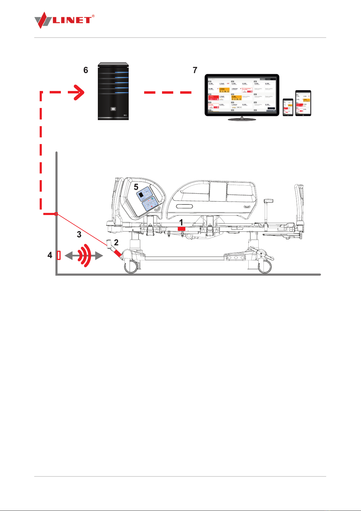
Eleganza 5 with SafetyMonitor system
Fig. SafetyMonitor system connection diagram (Eleganza 5)
1. Integration module (with Wi-Fi connection)
2. Localisation receiver and LAN connector
3. LAN cable
4. Localisation transmitter (Tag)
5. iBoard Standard
6. Server
7. User interface: PC, tablet, smartphone
12/46 D9U001SW0-0101_02
Eleganza 4 with SafetyMonitor system
Fig. SafetyMonitor system connection diagram (Eleganza 4)
1. Integration module (with Wi-Fi connection)
2. Localisation receiver and LAN connector
3. LAN cable
4. Localisation transmitter (Tag)
5. iBoard Basic
6. Server
7. User interface: PC, tablet, smartphone
D9U001SW0-0101_02 13/46
4.1 User Interface
Dashboard (displayed on-screen in the SafetyMonitor application) is the main control and display component of Safety-
Monitor. This user interface is used by nurses to check the Bed Exit monitoring of all beds connected to the system, to
set up and monitor other clinical parameters on all connected beds and to work with the system. Usually, user interface
screens are located in the nurse station or in visible places in the medical facility corridors.
4.2 Localisation Transmitter (Tag)
Tag is placed on the room wall in front of each bed.
It is powered by an internal battery (part of Tag), so no installation of power distribution is required.
Tag sends an infrared signal indicating its identifi cation and battery charge status.
Tag is installed on the wall by gluing. Installation is carried out at a height of 20 cm above the fl oor surface, in front
of the bed in the middle of the parking position. Tag life is 5 years. It is necessary to replace Tag after this time.
Tag can recognize and identify a bed located in a defi ned parking position (i.e. a room space intended for bed operation)
within the hospital. Tag is a standard part of SafetyMonitor. Thanks to the position information of the bed, SafetyMonitor
can display where the bed is located, and it monitors its data within pre-defi ned parking positions.
The localisation set for each bed consists of 2 parts: Tag (transmitter) on the room wall and receiver on the bed. To local-
ise the bed, the integration module (IM), which transmits localisation information to the server, also needs to be mounted
on the bed.
NOTE: Change of the bed position will be displayed on the ward terminal in about 3 to 9 minutes after the
physical change of the bed position.
4.3 Localisation Receiver
The system receiver is located on the front of the bed chassis so that it is directly visible on Tag.
The receiver is connected via cable to the IM from which it is powered and to which it transmits information about
the found Tag.
For the system to function properly, it is necessary to ensure direct visibility between Tag (transmitter) and the
receiver on the bed. Any object covering the receiver or transmitter (bed accessories, bedding ,etc.) will disable the func-
tion.
4.4 Bed Parking Position
WARNING!
In order for the SafetyMonitor system to operate correctly and the receiver with the localisation transmitter to
pair, the centre of the head board must face the wall to where Tag is located!
The bed parking position is a specifi c place in the room intended for the bed location.
BED HANDLING
To transfer the bed to another parking space:
►Pull out the network cable from the socket / unplug the power cord and disconnect the LAN cable
When the bed is disconnected from the power supply, a warning sounds when the bed is powered by the emergency
battery only. In this case, it goes into sleep mode when SafetyMonitor does not work.
The set monitoring functions are active until the light display on the bed display goes out.
►Release the bed brake
►Park the bed in the new parking place and brake
►Plug the bed into the socket, or connect LAN
► Check that SafetyMonitor is ON
14/46 D9U001SW0-0101_02
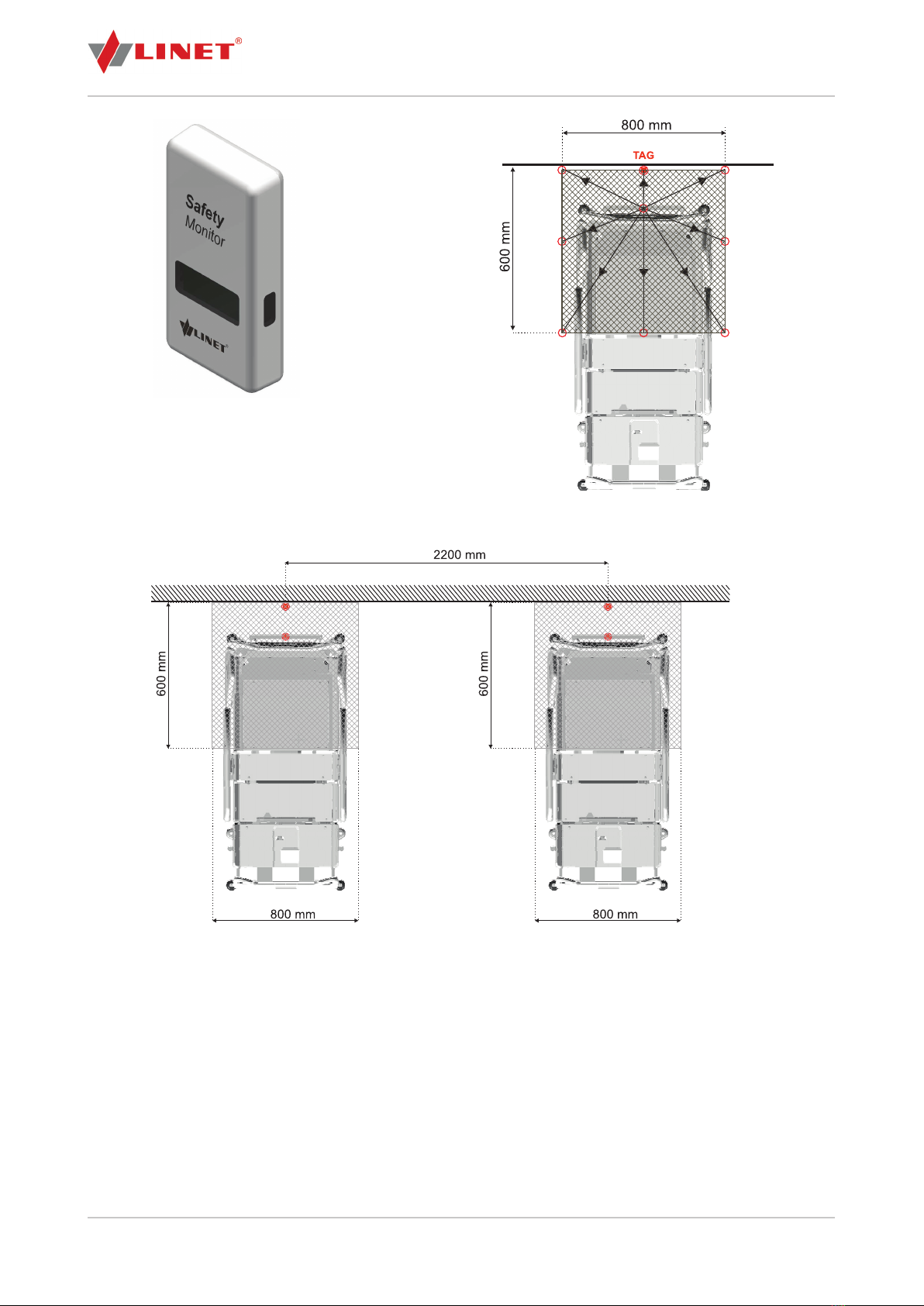
Fig. Distance between Tags
Fig. Possible location of the system localisa-
tion transmitter (Tag)
Fig. Tag on the wall
If there are more beds in the room, the distance between
Tags must be at least 2.2 m.
4.5 iBoard Standard (controller integrated in the head siderail)
The SafetyMonitor system controller is located in the head siderail (Eleganza 5 bed). It is used for setting and displaying
SafetyMonitor functions (Chapter 11).
4.6 iBoard Basic (controller integrated in the head siderail)
The SafetyMonitor system controller is located in the head siderail (Eleganza 4 bed). It is used for setting and displaying
SafetyMonitor functions (Chapter 11).

D9U001SW0-0101_02 15/46
5 Technical Specifi cations
5.1 Technical Requirements on the Part of the Customer
Internet connectivity Secure connection*
128kbit/s (upload) per 100 beds
400kbit/s (upload) per 100 beds in the graphical
interface
32kbit/s (upload) per 100 beds with export of
data to the hospital system (HIS)
Minimal server requirements Dual-core CPU 3GHz, 4GB RAM, 100GB HDD
Server operating system Linux OS (preferred), Windows server (2016, 2019
and later versions)
Data format for export to the HIS HL7 v2, xml, webservices
Computer network according to standards
LAN
WLAN
standards
IEEE 802.3
IEEE802.11 (802.11b/g, WPA/WPA2-PSK)
Graphical interface for display at the nurse station IE11 and higher, Google Chrome
* - A secure connection is not a condition on the part of the customer. However, without a secure connection, LINET® is
unable to provide remote installation support in case of complications.
5.2 Technical Specifi cations
Tag (on the wall)
Dimensions 80 x 40 x 17 mm
Weight 100 g
Material ABS UL 94-HB
Battery
Battery life
Integrated battery, not replaceable
5 years
Tag location (from the ground) 200 mm (margin: +0 mm, -20 mm)
Minimum spacing between Tags 2200 mm
Integration module
Battery
Battery life
Integrated battery, not replaceable
10 years
Bed Exit monitoring
Minimum volume of Bed Exit Alarm (sound pressure level of the
alarm signal)
60 dBA
Medium volume of Bed Exit Alarm (sound pressure level of the
alarm signal)
63 dBA
Maximum volume of Bed Exit Alarm (sound pressure level of the
alarm signal)
69 dBA
The necessary power interruption time after which the alarm
system is unable to reset the alarm that preceded the power
interruption
10 years
Inner Zone dimensions (Inner Zone Bed Exit monitoring) 50 cm x 45 cm

16/46 D9U001SW0-0101_02
6 Electrical Specifi cations
DANGER!
Fatal electric shock danger!
Please ensure that servicing and maintenance of the system are carried out only by a qualifi ed and certifi ed ser-
vice organisation when the system is connected to the electricity.
6.1 Electrical Specifi cations
Maximum power input Max. 0.15 W
Integration module lithium battery (CR2032)
Votage
Capacity
3V
200 mAh
Tag lithium battery (CP752425)
Votage
Capacity
3V
900 mAh
Ingress protection IP54
6.2 Electronic Compatibility
Control unit
(Eleganza 5)
(Eleganza 4)
PB46.12 (8211-4612F and higher)
PB43 RED (8211-44xB and higher)
Scales module 8300-0694C or 8300-0695C or 8300-696B
iBoard Standard (Eleganza 5) iBS (8213-48xxB and higher)
iBoard Basic (Eleganza 4) iBB (S6016631B and higher)
Integration module IM (S6017678)
Localisation receiver Localisation receiver (S6013858D and higher)
EMR ready bed CE:04 (EMR ready design)
EMR bed CE:31 (EMR design)
Tag Tag (S6013854B and higher)
NOTE: Installation scope of the SafetyMonitor system on a bed Eleganza 5 or Eleganza 4 depends on whether the bed
is equipped with CE:04 (EMR ready design) or with CE:31 (EMR design).
6.3 Electromagnetic Compatibility
The Eleganza 5 bed and Eleganza 4 bed with SafetyMonitor are suitable for hospitals except for near active VF
surgical instruments and RF shielded rooms for magnetic resonance systems where EM interference is high.
The Eleganza 5 bed and Eleganza 4 bed with SafetyMonitor has no defi ned essential functionality.
List of used cables:
Network cable, maximum length 6m
Supervisor Control Panel cable, maximum length 3m
Hand control cable, maximum length 3m
WARNING!
The use of this unit next to or in a block with other devices should be avoided, as this may cause improper
operation. If this is necessary, this device and other devices should be monitored to ensure that they operate
normally.

D9U001SW0-0101_02 17/46
WARNING!
Use of accessories, transducers, and cables other than those specifi ed or provided by the manufacturer of
this device could cause increased electromagnetic emissions or reduce the electromagnetic resistance of this
device and cause improper operation.
WARNING!
A portable RF communications device (including end devices such as antenna cables and external antennas)
should not be used closer than 30 cm (12 inches) from any part of the Eleganza 5 bed or Eleganza 4 bed with
SafetyMonitor system, including cables specifi ed by the manufacturer. Otherwise, this device may malfunc-
tion.
6.3.1 Instructions and Manufacturer’s Declaration – Electromagnetic Radiation
Radiation test Conformity
High-frequency radiation
CISPR 11
Group 1
High-frequency radiation
CISPR 11
Class A
Harmonic radiation
IEC 61000-3-2
Class A
Voltage fl uctuations/fl ickering radiation
IEC 61000-3-3
Compliant
6.3.2 Instructions and Manufacturer’s Declaration – Electromagnetic Immunity
Immunity test Compliant level
Electrostatic discharge (ESD)
IEC 61000-4-2
± 8 kV for contact discharge
± 15 kV for air discharge
Nearby fi elds from RF wireless communication devices
IEC 61000-4-3
See Table 1
Fast electric transient phenomenon/pulse group
IEC 61000-4-4
± 2 kV repetition rate 100 kHz
Surge
IEC 61000-4-5
± 1 kV pooled
± 2 kV between phase and ground
Guided high frequency
IEC 61000-4-6
3 V (0,15 MHz – 80 MHz)
6 V in ISM bands between 0.15 MHz and 80 MHz)
80 % AM at 1 kHz)
Power frequency magnetic fi eld (50/60 Hz)
IEC 61000-4-8
30 A/m
Short-term voltage drop and voltage interruption (power)
IEC 61000-4-11
0 % UT; 0.5 cycle
At 0°, 45°, 90°, 135°, 180°, 225°, 270° and 315°
0 % UT; 1 cycle and 70 % UT; 25/30 cycles
Single phase: at 0 °
0 % UT; 250/300 cycles
WARNING!
Do not overload the bed over the permissible safe working load (SWL), observe the duty cycle (INT.) and
follow the maintenance guidelines for the bed and SafetyMonitor components to maintain the basic bed and
SafetyMonitor safety in terms of electromagnetic interference throughout the bed life expectancy.

18/46 D9U001SW0-0101_02
Table 1 - Electromagnetic immunity, telecommunication services according to IEC 61000-4-3
Testing frequency
(MHz)
Band
(MHz)
Service Modulation Immunity test
level
V/m
385 380 - 390 TETRA 400 Pulse modulation 18 Hz 27
450 430 - 470 GMRS 460, FRS 460 FM ± 5 kHz deviation 1
kHz sinus wave
28
710
745
780
704 - 787 LTE band 13, 17 Pulse modulation 217 Hz 9
810
870
930
800 - 960 GSM 800/900, TETRA
800, iDEN 820, CDMA
850,
LTE band 5
Pulse modulation 18 Hz 28
1,720
1,845
1,970
1 700 - 1 990 GSM 1800; CDMA
1900; GSM 1900;
DECT; LTE band 1, 3,
4, 25; UMTS
Pulse modulation 217 Hz 28
2,450 2 400 - 2 570 Bluetooth, WLAN,
802.11 b/g/n, RFID
2450,
LTE band 7
Pulse modulation 217 Hz 28
5,240
5,500
5,785
5 100 - 5 800 WLAN 802.11 a/n Pulse modulation 217 Hz 9
NOTE: No deviations from EMC standard requirements are applied.
NOTE: No further measures are known to maintain essential EMC safety.
NOTE: Beds equipped with an integration module operate in the IEEE 802.11 b/g/n standard (2,400 to 2,483.5 MHz,
DSSS modulation (IEEE 802.11 b), OFDM (IEEE 802.11 g/n) 20MHz bandwidth, EIRP = 0.34 W.

D9U001SW0-0101_02 19/46
7 Scope of Delivery and Product Variants
► After receipt, check that the delivery is complete as indicated in the delivery note.
► Notify the carrier and supplier immediately of any defi ciencies or damages, either in writing or by recording it in
the delivery note.
SafetyMonitor (hardware):
Integration module
Merge box (Eleganza 4)
Siderail sensors
Backrest sensors
Brake sensors
Chassis module (optional)
Localisation sensor
Localisation cable
Integration module cable
LAN connector
The composition of the delivery is individual and depends on the selected product version, client requirements, infrastruc-
ture and other facts arising from local conditions (use of construction materials, number of parking spaces for beds in the
room, connection to the HIS system, etc.)
To operate the system, it is necessary to install a server that is a mandatory part of the delivery.
For the system to work properly, each bed must also be equipped with a control unit and an integration module. Each
EMR bed has 1 Tag (location transmitter, ...). To view the application remotely (at the nurse station), a monitor installation
is required (optional delivery).
8 Putting into Service
During the initial installation, a LINET® service technician (or partner) fi rst installs the beds and location Tags in hospital
rooms and ensures they are connected to the server. Then the technician sets up the Administration Interface, especially
the wards and rooms according to the hospital internal structure and creates parking spaces. This can be done remotely.
8.1 SafetyMonitor Installation
Installation prerequisites:
Functional internet infrastructure
Stable display monitor
Ready to install server
Remote access to the server
Installation of beds
Installation steps:
Server installation
Communication of Eleganza 5 beds or Eleganza 4 beds with server
Localisation system installation (EMR bed + Tag)
Installation of HL7 v2 hospital information system (optional)
Test of the functional connection of bed, server and display monitor
Technical training
Clinical training

20/46 D9U001SW0-0101_02
8.3 Transporting the Bed
CAUTION!
Damage to the system due to incorrect preparation before moving!
The bed may be moved only after the Ethernet cable has been disconnected from the local computer network (if
it is connected to the local network with cables) and after the bed has been disconnected from the electricity.
When moving the bed (e.g., from one room to another, from room to theatre, etc.), it is essential to disconnect the bed
from the local computer network (if cable connection is used) and the network cable from the electricity. When the bed is
being moved, the given bed is not monitored or localised.
8.2 Tag Installation
CAUTION!
The Tag box must be installed upright (1). The distance between the bottom edge of Tag and the fl oor must be
17 cm!
If the distance from the fl oor is smaller, the proper function of the system cannot be guaranteed and the bed can
be displayed in a position other than the one it is actually in!
CAUTION!
Every Tag has its serial number!
Make a note of the serial numbers of the installed Tags along with their positions! Tag serial number is listed on
the back on the Tag ID.
Tag installation steps:
►Specify the Tag position on the wall. Tag must be placed on the wall directly in the middle of the bed's parking
position. The distance between two Tags must be at least 2.2 meters. The Tag bottom edge must be just 17 centimetres
above the fl oor.
► Remove Tag from the box (1).
►Glue Tag to the correct position on the wall. If it is necessary to adjust the wall so Tag holds reliably, use dowels
and screws (3) to attach a tin plate to the correct position on the wall (2), to which Tag is then glued.
1
3
2
Fig. Bottom of the Tag box (serial number) Fig. Contents of the Tag box
This manual suits for next models
1
Table of contents
Other LINET Measuring Instrument manuals

Popular Measuring Instrument manuals by other brands

Contrel
Contrel ELRC-1 instruction manual

Fuji Electric
Fuji Electric PUM instruction manual

Kessler-Ellis Products
Kessler-Ellis Products MINItrol Series Installation & operating instructions

PCE Instruments
PCE Instruments PCE-HT 110 user manual

VEE GEE
VEE GEE BTX-20 Operation manual

Simpson
Simpson Gima instruction manual


Full Spectrum Laser
Full Spectrum Laser FSL300 user manual

Xylem
Xylem SENSUS PolluTherm user manual

WB Johnson Instruments
WB Johnson Instruments AM-801 Operation & maintenance manual

Endress+Hauser
Endress+Hauser Turbimax CUE21 operating instructions

Moeller
Moeller Xcomfort CTEU-02/01 Assembly instructions

TPI
TPI 1010a manual