Lingenfelter RPM-003 User manual

Lingenfelter RPM-003
Digital RPM Controlled Window Switch
with Analog Input
Installation Instructions
PN: L460160000
1557 Winchester Road
Decatur, Indiana 46733
(260) 724-2552 phone
(260) 724-8761 fax
www.lingenfelter.com
Release date: 24 October 2016
v2.3

Page 2
Parts List
# Description Part number
1 LPE digital RPM controlled window switch with analog input RPM-003
1 Hook & loop tape
2 Self-tapping screw AV16037
1 LPE decal L920010000
1 Instructions
Optional Items
Description Part Number
• Red 7 LED warning light, 10 ft two wire cable RP-WLRBLK001
• Sealed 40 amp heavy duty relay kit L450100000
• LPE Technician’s Screwdriver L950050000
• E38/E67 ECM terminal 0334680003
Specications:
• The Lingenfelter Performance Engineering RPM-003 RPM Controlled Switch incorporates a precision 32-bit timer to
realize microsecond precision over a very wide operating RPM range. Most common tachometer pulse frequencies are
supported with no additional components required.
• The RPM-003 can perform as a standard RPM activated switch or it can provide “Window” switch type capability,
switching at one RPM level and then switching back at a second RPM level.
• Available output types:
• Normally ON ground
• Normally OFF ground
• Normally OFF +12vdc
• All three outputs (+12v activation normally OFF, GROUND activation normally ON and OFF) can be used simultaneously.
• Current draw: 0.1 amp plus current draw of device being controlled (when active).
• Outputs rated for up to 0.75 amps each.
• The RPM switch should control a relay for higher current level applications.
• Outputs have a self protect feature and will turn OFF in case of a direct short or over current condition.
• Includes a built in 2.2k Ohm tachometer pull up resistor enabled by a DIP switch inside the back cover.
• Operating voltage range: 9.0 to 18.0 volts.
• Input signal type: +12 volt DC square wave or coil negative terminal and +5 volt DC reference signal applications.
• Accepts both traditional 12 volt tachometer signals and also accepts 5 volt reference engine speed signals found on
many newer cars, trucks and motorcycles.
• Analog 0-5 volt input that can accept a Throttle Position Sensor (TPS), Clutch Pedal Position (CPP) sensor, Accelerator
Pedal Position (APP) sensor, Manifold Absolute Pressure (MAP) sensor, or most any other rising or falling 0-5 volt signals.
• RPM switch settings can be adjusted in 100 RPM increments from 400 to 19900 RPM.
• Adjustable RPM hysteresis settings of 0, 50, 100, 150, 200, 250, 300, and 350 RPM.
• CustommoldedhightemperatureglasslledNylon6enclosure.
• Fully encapsulated (potted) construction for increased durability.
• When operated in standard RPM activated switch mode, the RPM-003 can be a shift light controller. For shift lights that
draw more than 0.75 amps, a relay would need to control the light.
• Input signal impedance: 100k ohms.
• One year warranty (from date of purchase).

Page 3
Table A - Wiring (also labeled on module):
Wire color Label Notes
Red +12 Vdc Connects to a switched and fused +12 volt DC source.
Orange Normally Off +12
Vdc Output
Thisisthenormallyopen(off)+12Vdcoutputwire.+12Vdcwillowthroughthiswirewhen
the switch is activated. This connects to the +12 Vdc side of the device you plan to control.
Black Ground Connects to a vehicle ground.
Purple Analog Input This connects to the analog signal output wire of a clutch pedal position sensor, throttle position
sensor, MAP sensor, or other rising or falling 0-5 volts signal sensors.
Gray Normally On
Ground Output
This is the normally closed (on) ground output wire. This wire will open the ground path when
the switch is activated. This connects to the ground side of the device you plan to control.
Yellow Normally Off
Ground Output
This is the normally open (off) ground output wire. This wire connects to ground when switch is
activated. This connects to the ground side of the device you plan to activate.
White Tach Input This is the RPM input wire. This connects to your RPM signal wire.
Settings:
• Controlledbyonesixteenpositionswitch,fourtenpositionswitches,veDIPswitches,andonepushbutton.
Settings on the front face of the RPM-003:
• Single sixteen position switch for selecting pulse per revolution count. Refer to Table B on page 16 for a list of various
vehicle applications and their correct pulse per revolution setting.
• First half of the range is the Low Range (9,900 &
below). Low range should be selected if the RPM
switch point will occur below 9,900 RPM.
• Second half of the range is for the High Range
(10,000+ RPM). High Range mode should be used if
the RPM switch point will occur above 9,900 RPM.
High Range mode only applies to the RPM #2 range.
• Two ten position switches for selecting the RPM #1
• RPM x1000
• RPM x100
• If set to zero, the RPM-003 functions in RPM switch
mode. With RPM #1 set to zero, the outputs will be
swapped from what is labeled on the RPM-003 (i.e.
+12 normally OFF output is now normally ON) until
RPM #2 is reached. See the activation charts on page
17forclaricationoftheswitchlogic.
• If RPM #1 and RPM #2 are both non-zero, the RPM-
003 functions as a window switch, which means that
theoutputswillchangetheirconditionwhentherst
switch point is reached, and then will switch back to the their original condition when the second switch point is
reached.Seetheactivationchartsonpage17forclaricationoftheswitchlogic.
• Two ten position switches for selecting the RPM #2
• RPM x1000 (10000 RPM is added to this setting when in High Range)
• RPM x100
• If set to zero, the RPM-003 functions in RPM switch mode. With RPM #2 set to zero, the outputs will remain
aslabeledontheRPM-003untilRPM#1isreached.Seetheactivationchartsonpage17forclaricationofthe
switch logic.
• RPM #1 MUST BE LESS THEN RPM #2 IF BOTH SETTINGS ARE NON-ZERO VALUES.
Power
RPM-003
RPM Window Switch
Ground - Black
Normally On - Gray
Normally Off - Yellow
with Analog Input
RPM #1 x1000
RPM #1 x 100
+12V Switched Power - Red
RPM #1
RPM #2 x1000
RPM #2 x100
RPM #2
Analog Input Signal - Purple
+12V Output Norm Off - Orange
Tach Input Signal - White
.5
1
2
3
45
1.5
2.5
.5 11.5
2
2.5
3
4
5
High Range
+10,000 Off Rpm
Low Range

Page 4
Settings inside the rear cover of the RPM-003:
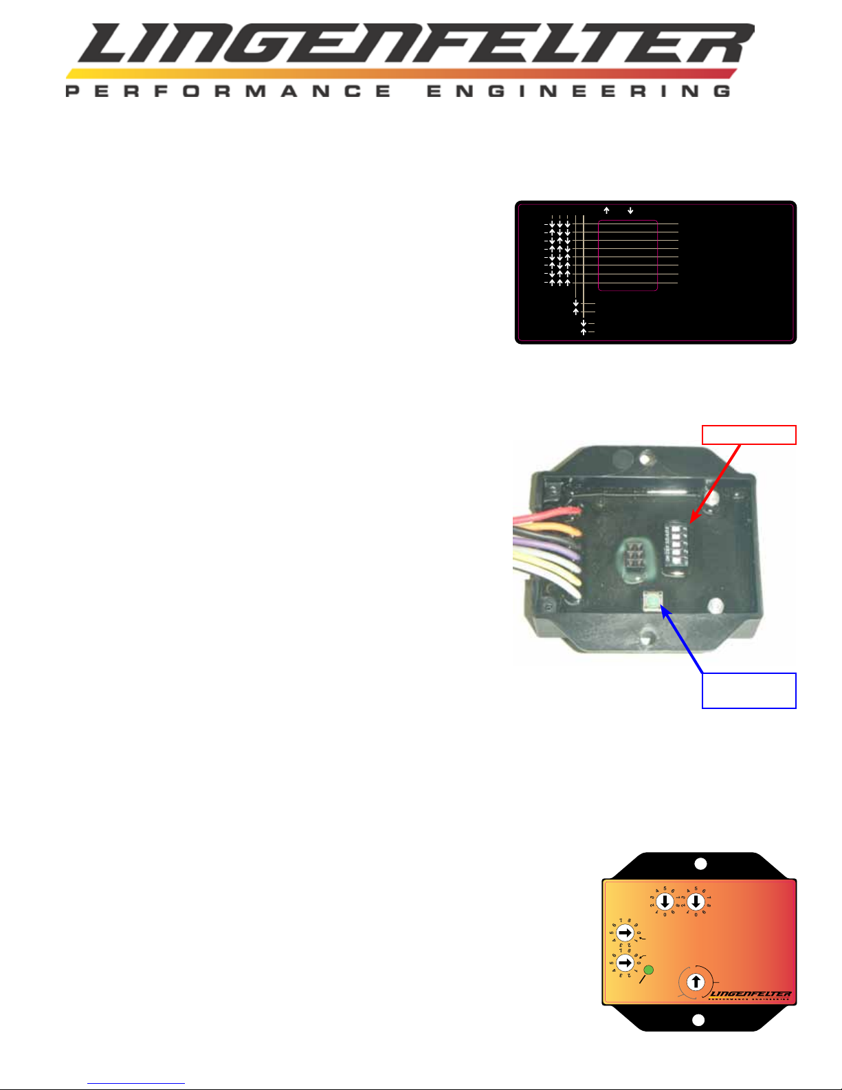
• Five two position DIP switches (The location of these switches are shown in
Figure 2.)
• DIP switches #1-3 select desired RPM hysteresis (The hysteresis DIP
switch settings are shown in Figure 1.)
• The RPM-003 features RPM hysteresis settings of 0, 50, 100, 150,
200, 250, 300, and 350 RPM.
• When an RPM hysteresis is enabled, the RPM-003 will still switch
at the RPM set point (which is set by the RPM #1 and/or RPM #2
settings), but the RPM-003 will not switch again until the set point
and the hysteresis is reached. (i.e. RPM-003 will switch at 4500
RPM but will not switch back until engine speed falls below 4300
RPM due to a 200 RPM hysteresis).
• It is recommended to use at least a small amount of hysteresis as it
is possible for the RPM-003 to continually switch the outputs on
andoffiftheRPMisheldattheuser-denedRPMswitchpoint
with no hysteresis.
• DIPswitch#4togglesanaloginputONorOFF(xedat90%trippoint
with2%hysteresis)
• This option can be used to activate the outputs on the RPM-003
based on a 0-5 volt analog input signal from the following vehicle
sensors:
• Throttle Position Sensor (TPS)
• Clutch Pedal Position (CPP) sensor
• Accelerator Pedal Position (APP) sensor
• Manifold Absolute Pressure (MAP) sensor
• Or any other rising or falling 0-5 volt signal
• When this option is enabled, the outputs will not activate until
both the RPM set point and the analog input trip point have been
reached.
• This function can be used in nitrous applications to prevent nitrous
oxide from being released prematurely (before BOTH the RPM set
point and analog input trip point has been reached)
• Dip switch #5 toggles the built in tachometer pull-up resistor ON or OFF
• This option is normally used when connecting to the engine speed signal output from the ECM through a
circuit that does not have a pull-up resistor installed. On vehicles that already have this signal connected to
another system or module, a pull-up resistor is most likely already present in the circuit. You DO NOT want
to have multiple pull-up resistors in the circuit. Vehicles that have a pull-up resistor in the instrument cluster
(such as C5 and C6 Corvettes) will require the RPM-003’s pull-up resistor feature to be disabled as it will
create too much resistance in the circuit. Vehicles that do not have a pull-up resistor in the instrument cluster
(such as 2010-2013 Camaro and 2007-2012 CK trucks) should have this feature enabled if you plan to connect
to the ECM signal source.
• ONLY use the tachometer pull-up setting when connected to a TACH signal.
Enabling this when connected a coil or injector may cause a check engine light
and/oramisretooccur.
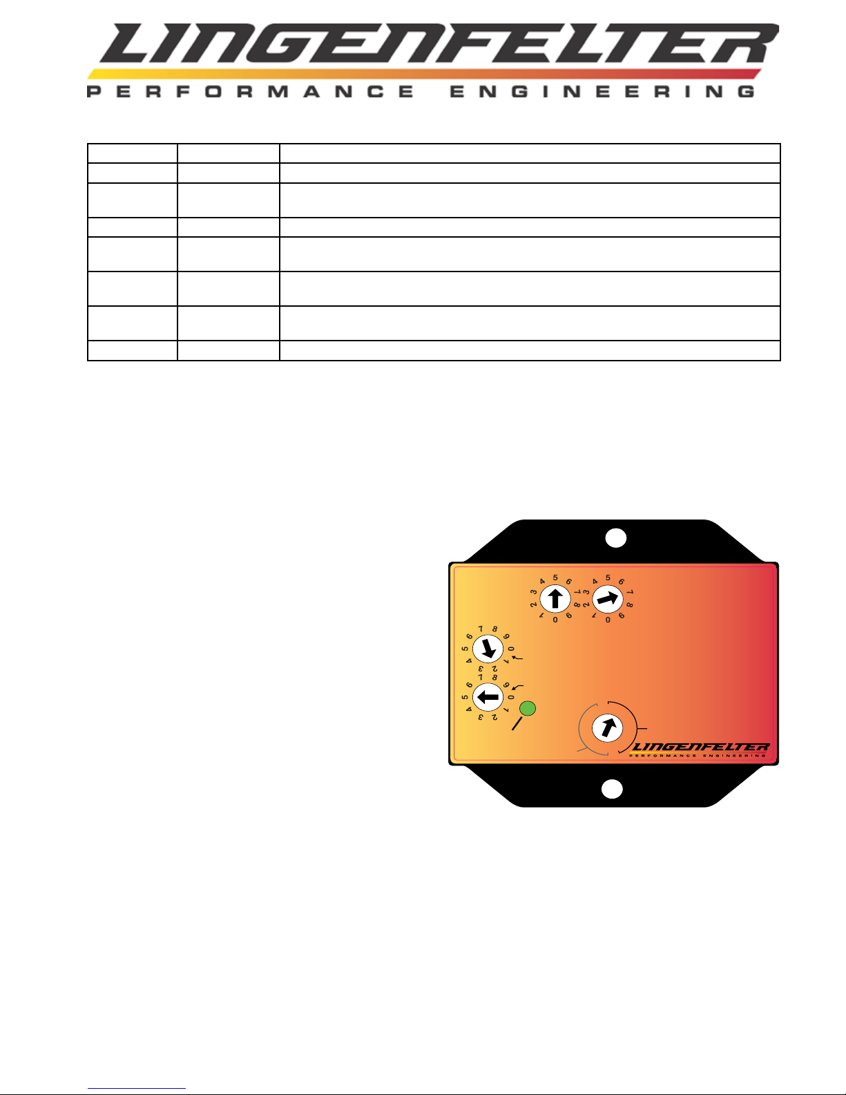
• One push button (The location of this button is shown in Figure 2.)
• Used to program the analog input voltage range when device is in programming mode
• In order for the device to enter programming mode, all four 10 position switches must
be set to zero and the 16 position switch must be set to 0.5, low range (arrow pointing
straight up). See illustration on the right for switch positions.
123 ON OFF
0
1
2
3
4
5
6
7
RPM HYSTERESIS
0 RPM - HYSTERESIS OFF
50 RPM
100 RPM
150 RPM
200 RPM
250 RPM
300 RPM
350 RPM
4 5
SWITCH #4
SWITCH #5
ANALOG INPUT OFF
ANALOG INPUT ON
TACH INPUT PULL-UP RESISTOR OFF
TACH INPUT PULL-UP RESISTOR ON
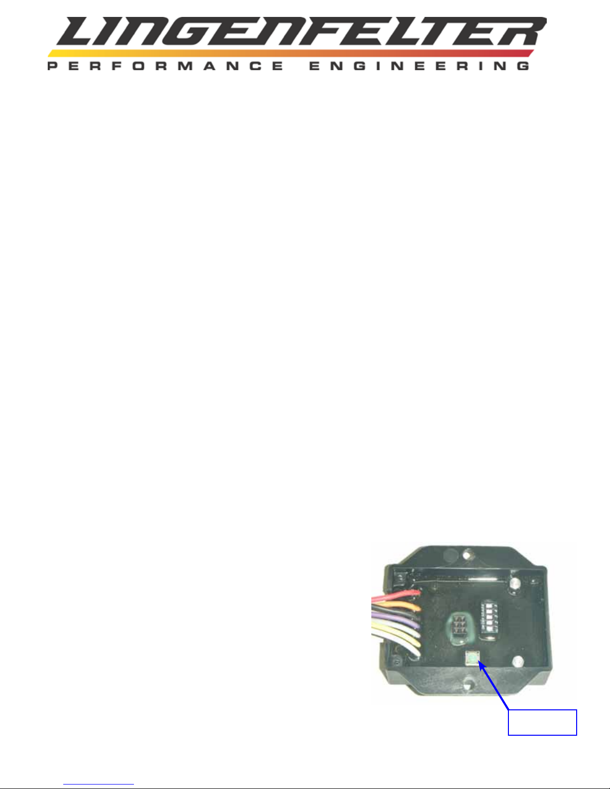
DIP Switches
Programming
Button
Figure 1: DIP switch settings label
(also found on the backside of the
RPM-003 back cover).
Figure 2: Location of components
inside the RPM-003’s back cover.
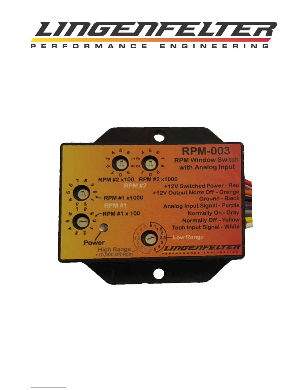
Power
RPM-003
RPM Window Switch
Ground - Black
Normally On - Gray
Normally Off - Yellow
with Analog Input
RPM #1 x1000
RPM #1 x 100
+12V Switched Power - Red
RPM #1
RPM #2 x1000
RPM #2 x100
RPM #2
Analog Input Signal - Purple
+12V Output Norm Off - Orange
Tach Input Signal - White
.5
1
2
3
45
1.5
2.5
.5 11.5
2
2.5
3
4
5
High Range
+10,000 Off Rpm
Low Range

Page 5
Operation LED Status:
• Solid RED when the unit is powered up but no tachometer signal is detected
• Solid GREEN when a tachometer signal is detected, but is not within the RPM window or has not reached the RPM
activation point
• GREEN blinking when outputs are active in RPM switch mode or Window switch mode
• GREEN blinking when module is in programming mode (all 10 position switches set to zero and 16 position switch set
to 0.5, low range)
• Blinking GREEN+RED after the programming button has been pressed and the RPM-003 is recording the analog input
voltages. The LED will continue blinking GREEN+RED until two sweeps (from closed throttle/released clutch to Wide
Open Throttle/depressed clutch) of at least 1.5 volts are taken. Once this parameter is met, the LED will change to one
of the following colors:
• Inprogrammingmode,asolidREDLEDsigniesthattheprogrammingoftheanalogvoltagerangewas
successful.
• BlinkingREDwhenanerroroccurs,whichcanbexedbyreprogrammingthemodule.Thefollowingconditions
must be met for the programming to be successful:
• The range between the closed throttle/released clutch voltage and the wide open throttle (WOT)/depressed
clutch voltages must be at least 1.5 volts.
• ThedifferencebetweentherstWOT/depressedsignalvoltageandthesecondWOT/depressedsignalvoltage
must be less than or equal to 0.1 volts.
Installation:
• Disconnectthenegativebatteryterminal.
• ConnectblackwireofRPMswitchtoasuitablevehicleground.Failure to fully secure the ground wire to a vehicle
ground source could result in malfunction of the module.
• Connecttheredwiretoaswitched and fused +12 volt DC source. The +12vdc source that the red wire is connected to
shouldbepoweredanytimetheECMispowered.A5-10ampfuseshouldbesufcient,butrememberthateachoutput
is rated for up to only 0.75 amps, so a relay should be used if any of the RPM-003 outputs will be controlling a device
that pulls more than 0.75 amps.
• ConnectthewhitewiretotheRPMsignalsource.Thiscanbethetachometeroutputleadofthevehicle,theswitched
side of the ignition coil (negative side) or the 5 volt RPM reference signal.
• See Table A on page 15 for information on some of the common vehicle ECM/PCM tachometer signal wiring
information.
• IfyouwillbeusingtheNormallyOff(open)groundactivationoutput,suchastocontrolashiftlight,connectthe
yellow wire to the ground side of the device you plan to activate.
• IfyouwillbeusingtheNormallyOn(closed)groundactivationoutput,connectthegraywiretothegroundsideofthe
device you plan to activate.
• If you will be using the Normally OFF (open) +12 Vdc activation output, connect the orange wire to the +12 Vdc side of
the device you plan to activate.
• If you will be using the analog input, connect the purple wire to a rising or falling 0-5 volt analog signal wire running
from the TPS, CPP sensor, APP sensor, MAP sensor, or other analog 0-5 volt signal vehicle sensor.
• Ifthedeviceyouwillbecontrollingdrawsmorethan0.75amps,makesuretocontrolthedevicethrougharelay.
• SecuretheRPM-003usingthesuppliedhookandlooptapeorusingthesuppliedself-tappingscrews.
• SettheInputSignalPulsePerRevolutionswitchtothecorrectsettingforyourvehicleapplication.SeeTableBonpage
16 for the settings.
• Set the DIP switch settings inside the back cover of the module. Refer to page 3 for an explanation of DIP switch
settings (hysteresis, tach pull-up, and analog input) and to Figure 1 on page 3 for a table of DIP switch settings.
• Reconnectthenegativebatteryterminal.

Page 6
Additional Notes and Warnings:
• Changes to the switch settings must be done with the RPM-003 powered off.
• The switch positions are only read on start up (initial device power up).
• The low RPM setting (RPM #1) must be less than the high RPM setting (RPM #2) if both are non-zero values (window
switch mode). If RPM #1 is greater than or equal to RPM #2, the outputs can never be active because the condition can
never be met.
• The RPM Controlled Switch will not work at RPM levels below 400 RPM.
• The minimum difference between the ON RPM and the OFF RPM when in Window Switch mode is 500 RPM.
• The minimum difference between the minimum and maximum analog voltage is 1.5 volts.
• MakesurethattheRPM-003groundwireissufcientlysecuredtoavehicleground.FailuretofullysecuretheRPM-003
ground wire to a vehicle ground source could cause the RPM-003 to malfunction
• Do NOT submerge the module in liquid or directly wash the unit with liquid of any type! The switches on the RPM-003 are
sealed but are NOT rated for high pressure washing, use caution if power washing near the RPM-003 module.
• Do NOT mount the RPM-003 directly on top of the engine or near the exhaust manifolds due to heat concerns.
• Do NOT mount the RPM-003 in the line of site of high temperature objects such as exhaust manifolds, turbine housings
etc. If needed, install a heat shield in between the heat source and the module to protect the plastic case.
• DoNOTinstallwithin6”ofnitroussolenoidsorotherdeviceswithstrongmagneticelds.
• Do NOT install near the spark plugs or the spark plug wires (or other potential strong sources of electrical noise).
• LPE recommends the use of resistor type spark plugs and RFI (radio frequency interference) and EMI (electromagnetic
Interference) suppression spark plug wires on all EFI engines and any vehicle that has electronic control modules on board
(including the RPM-003). Failure to do so may result in erratic operation of electronic devices including the RPM-003.
• It is important to note that the throttle on an electronic throttle body is usually not fully closed with the vehicle keyed on
andtheengineoff.Becauseofthis,theanaloginputtrippointof90%ontheRPM-003maynotmatchthe90%TPSvalue
displayed on the scan tool.
• The connection of this device to an electronic throttle body should be done on off-road and racing applications only.
• Caution must be taken if you are going to wire the purple analog input wire from the RPM-003 into the wire
that relays the throttle position between the ECM and an Electronic Throttle Body. On Electronic Throttle Body
equipped (or drive-by-wire) vehicles, DTC codes or even a disabled vehicle could result if the electronic throttle
body loses its connection to the ECM. While every effort has been made by LPE to test the RPM-003 on a variety
of vehicles, we can not guarantee that this module will work with every electronic throttle currently in use. If this
module causes the ECM to set a code or causes any other engine operation issues, disconnect and discontinue the use
of this module IMMEDIATELY.
Programming Analog Input Signal Range:
1. To put the RPM-003 in programming mode, all four 10 position switches
must be set to zero and the 16 position switch must be set to 0.5, low range
(arrow pointing straight up). The position of the DIP Switches do not have
to be changed. Upon powering up the unit, the LED on the RPM-003
should now be blinking GREEN.
2. Using a #1 Phillips head screwdriver, remove the back cover on the
RPM-003 to access the green programming button. The location of the
programming button is shown in the adjacent illustration.
Programming
Button

Page 7
3. With the vehicle keyed on, the engine off, and the clutch or accelerator pedal fully released, press the green
programming button on the back of the RPM-003. The LED should now be blinking RED+GREEN. The RPM-003 will
now take the current closed throttle voltage or released clutch voltage, depending on which sensor you connected the
RPM-003’s purple analog input wire to.
4. Fully depress and then fully release the pedal that the RPM-003 is connected to (throttle or clutch) two times. The
RPM-003willndtheaverageofthetwodepressedvoltagesandthencomparetheaveragetothereleasedvoltage
to determine whether the calibration is valid. If the LED turns solid RED, the calibration was successful and is
programmed into memory. If the LED begins to blink RED, the calibration was unsuccessful for one of the following
reasons:
• The range between the closed throttle/released clutch signal and the wide open throttle (WOT)/depressed clutch
voltages must be at least 1.5 volts.
• ThedifferencebetweentherstWOT/depressedvoltageandthesecondWOT/depressedvoltagemustbelessthan
or equal to 0.1 volts.
5. If an error occurs, simply power down the RPM-003 and re-program the pedal position voltages.
Example settings:
GM LS1/LS6/LS2 V8 engines with tachometer signal from ECM/PCM (1997-2013 Corvette, 1998-2002 Camaro/
Firebird, 1999-2006 C/K truck, 2004-2006 GTO):
• Connect white Tachometer Input Signal wire to ECM/PCM tachometer output -- see page 15 for tachometer signal wire
information.
• (1800 RPM) RPM switch mode example with no hysteresis, analog input, or pull-up resistor:
o Sixteen position Input Signal Pulse Per Revolution switch set to Low Range and 2 pulses per revolution
o RPM #1 programming switch for thousands of RPM (X000) on position 1
o RPM #1 programming switch for hundreds of RPM (0X00) on position 8
○Both RPM #2 programming switches on position 0
○ DIPswitches1-5ippeddown(allDIPswitchesinOFFposition)
• NOTE - if this is a custom vehicle application using one of these ECM/PCM's and nothing is connected to the
tachometer signal or your aftermarket tachometer does not have a pull-up resistor then you will need to enable
the pull-up resistor using DIP switch # 5
•(1800 RPM - 6000 RPM) Window switch mode example with no hysteresis, analog input, or pull-up resistor
o Sixteen position Input Signal Pulse Per Revolution switch set to Low Range and 2 pulses per revolution
o RPM #1 programming switch for thousands of RPM (X000) on position 1
o RPM #1 programming switch for hundreds of RPM (0X00) on position 8
o RPM #2 programming switch for thousands of RPM (X000) on position 6
o RPM #2 programming switch for hundreds of RPM (0X00) on position 0
○ DIPswitches1-5ippeddown(allDIPswitchesinOFFposition)
• NOTE - if this is a custom vehicle application using one of these ECM/PCM's and nothing is connected to the
tachometer signal or your aftermarket tachometer does not have a pull-up resistor then you will need to enable
the pull-up resistor using DIP switch # 5

Page 8
2010-2015 Camaro and 2007-2013 GM CK trucks (Escalade, Denali, Tahoe, Yukon etc.) that do not have a
tachometer output wire:
•Connect the white Tachometer Input Signal wire to any of the 4 coil trigger wires on the coil harness to either bank
of cylinders, as shown on page 14 of the instructions. If you prefer to retrieve the tachometer signal from the ECM,
connecttheRPM-003totheECMbyrstpopulatingthecorrectpinandthenenablingtheoutputintheECM,as
shown on page 12 of the instructions. If you choose the latter method for obtaining the tachometer signal, refer to the
GM LS1/LS6/LS2 V8 engines with tachometer signal from ECM/PCM settings example on page 6 for the correct
settings (The RPM-003 tachometer pull-up resistor function will need to be enabled if you are populating a tachometer
wire in the ECM).
• (2700 RPM) RPM switch mode example with 100 RPM hysteresis, analog input disabled, and tachometer pull-up
resistor disabled
o Sixteen position Input Signal Pulse Per Revolution switch set to Low Range and 0.5 pulses per revolution
o RPM #1 programming switch for thousands of RPM (X000) on position 2
o RPM #1 programming switch for hundreds of RPM (0X00) on position 7
○Both RPM #2 programming switches on position 0
○Combination of DIP switches 1-3 set hysteresis of 100 RPM
• DIPswitch#1ippeddown(OFF)
• DIPswitch#2ippedup(ON)
• DIPswitch#3ippeddown(OFF)
○ DIPswitch#4(Analoginputactivation)flippeddown(OFF)
○ DIPswitch#5(Tachometerpull-upresistoractivation)flippeddown(OFF)
• Make sure the pull-up is OFF or you will set a diagnostic code and potentially cause an engine misfire to occur.
• (2700-5500 RPM) Window switch mode example with 100 RPM hysteresis, analog input disabled, and tachometer pull-
up resistor disabled:
o Sixteen position Input Signal Pulse Per Revolution switch set to Low Range and 0.5 pulses per revolution
o RPM #1 programming switch for thousands of RPM (X000) on position 2
o RPM #1 programming switch for hundreds of RPM (0X00) on position 7
o RPM #1 programming switch for thousands of RPM (X000) on position 5
o RPM #1 programming switch for hundreds of RPM (0X00) on position 5
○Combination of DIP switches 1-3 set hysteresis of 100 RPM
• DIPswitch#1ippeddown(OFF)
• DIPswitch#2ippedup(ON)
• DIPswitch#3ippeddown(OFF)
○ DIP switch #4 (Analog input activation) flipped down (OFF)
○ DIP switch #5 (Tachometer pull-up resistor activation) flipped down (OFF)
• Make sure the pull-up is OFF or you will set a diagnostic code and potentially cause an engine misfire to occur.
NOTE - when connecting to the coil wire it is critical that the RPM-003 be powered up whenever
the ignition is powered up. If you need to put a disable switch into the circuit make sure you
disable the output from the RPM-003 and keep the RPM-003 powered when the ignition is on. If
not you will likely cause a check engine light.

Page 9
Most earlier GM V8 electronic fuel injection (EFI) engine applications including L98, LT1 and LT4 engines:
• Connect white Tachometer Input Signal wire to PCM/ECM tachometer output -- see page 15 for tachometer signal wire
information.
• For analog input, connect the purple analog input wire to the Throttle Position Sensor, Clutch Pedal Position sensor, or
MAP sensor.
• 4500 RPM window switch example with 200 RPM hysteresis, analog input enabled, and tachometer pull-up resistor
disabled.
o Sixteen position Input Signal Pulse Per Revolution switch set to Low Range and 4 pulses per revolution
o RPM #1 programming switch for thousands of RPM (X000) on position 4
o RPM #1 programming switch for hundreds of RPM (0X00) on position 5
○Combination of DIP switches 1-3 set hysteresis of 200 RPM
• DIPswitch#1ippeddown(OFF)
• DIPswitch#2ippeddown(OFF)
• DIPswitch#3ippedup(ON)
○ DIP switch #4 (Analog input activation) flipped up (ON) -- only if connected to an analog input
○ DIP switch #5 (Tachometer pull-up resistor activation) flipped down (OFF)
• 1800-7200 RPM window switch example with 200 RPM hysteresis, analog input enabled, and tachometer pull-up
resistor disabled.
o Sixteen position Input Signal Pulse Per Revolution switch set to Low Range and 4 pulses per revolution
o RPM #1 programming switch for thousands of RPM (X000) on position 1
o RPM #1 programming switch for hundreds of RPM (0X00) on position 8
o RPM #2 programming switch for thousands of RPM (X000) on position 7
o RPM #2 programming switch for hundreds of RPM (0X00) on position 2
○Combination of DIP switches 1-3 set hysteresis of 200 RPM
• DIPswitch#1ippeddown(OFF)
• DIPswitch#2ippeddown(OFF)
• DIPswitch#3ippedup(ON)
○ DIP switch #4 (Analog input activation) flipped up (ON) -- only if connected to an analog input
○ DIP switch #5 (Tachometer pull-up resistor activation) flipped down (OFF)

Page 10
Most traditional single coil V8 applications:
• Connect white Tachometer Input Signal wire to the coil negative terminal
• 4500 RPM switch example with 200 RPM hysteresis, analog input disabled, and tachometer pull-up resistor disabled.
o Sixteen position Input Signal Pulse Per Revolution switch set to Low Range and 0.5 pulses per revolution (straight
up)
o RPM #1 programming switch for thousands of RPM (X000) on position 4
o RPM #1 programming switch for hundreds of RPM (0X00) on position 5
○Combination of DIP switches 1-3 set hysteresis of 200 RPM
• DIPswitch#1ippeddown(OFF)
• DIPswitch#2ippeddown(OFF)
• DIPswitch#3ippedup(ON)
○ DIP switch #4 (Analog input activation) flipped down (OFF)
○ DIP switch #5 (Tachometer pull-up resistor activation) flipped down (OFF)
• 4500-7200 RPM window switch example with 200 RPM hysteresis, analog input disabled, and tachometer pull-up
resistor disabled.
o Sixteen position Input Signal Pulse Per Revolution switch set to Low Range and 0.5 pulses per revolution (straight
up)
o RPM #1 programming switch for thousands of RPM (X000) on position 4
o RPM #1 programming switch for hundreds of RPM (0X00) on position 5
o RPM #2 programming switch for thousands of RPM (X000) on position 7
o RPM #2 programming switch for hundreds of RPM (0X00) on position 2
○Combination of DIP switches 1-3 set hysteresis of 200 RPM
• DIPswitch#1ippeddown(OFF)
• DIPswitch#2ippeddown(OFF)
• DIPswitch#3ippedup(ON)
○ DIP switch #4 (Analog input activation) flipped down (OFF)
○ DIP switch #5 (Tachometer pull-up resistor activation) flipped down (OFF)

Page 11
Most modern sportbike motorcycles including all years of the Suzuki GSXR-1300 Hayabusa, all years of the
Kawasaki ZX-14 and 2002 and newer Suzuki GSXR-1000:
•Connect white Tachometer Input Signal to one of the coil negative terminals
• (11,000RPM) RPM switch mode example with 300 RPM hysteresis enabled, analog input disabled, and tachometer
pull-up resistor disabled
o Sixteen position Input Signal Pulse Per Revolution switch set to High Range and 0.5 pulses per revolution
o RPM #1 programming switch for thousands of RPM (X000) on position 4
o RPM #1 programming switch for hundreds of RPM (0X00) on position 5
○Both RPM #2 programming switches on position 0
○Combination of DIP switches 1-3 set hysteresis of 300 RPM
• DIPswitch#1ippeddown(OFF)
• DIPswitch#2ippedup(ON)
• DIPswitch#3ippedup(ON)
○ DIP switch #4 (Analog input activation) flipped down (OFF)
○ DIP switch #5 (Tachometer pull-up resistor activation) flipped down (OFF)
• (6,000-12,500 RPM) Window switch mode example with RPM hysteresis disabled, analog input disabled, and
tachometer pull-up resistor disabled
o Sixteen position Input Signal Pulse Per Revolution switch set to High Range and 0.5 pulses per revolution
o RPM #1 programming switch for thousands of RPM (X000) on position 6
o RPM #1 programming switch for hundreds of RPM (0X00) on position 0
o RPM #2 programming switch for thousands of RPM (X000) on position 2
o RPM #2 programming switch for hundreds of RPM (0X00) on position 5
○ DIPswitches1-5ippedtothedown(OFF)
Installation notes:
• On most engines the Tachometer Input Signal wire can be connected to one coil negative terminal or wire (may have 1,
2 or 4 individual coils - just connect to one of these). Start at 0.5 pulse/revolution. If the RPM reads double, switch to 1
pulse per revolution.
• If connecting to an older vehicle (including motorcycles with analog ignitions and solid core spark plug wires),
interference may occur. If this happens modern noise suppression spark plug wires and spark plugs MUST be used.
• If connecting to an MSD or other multi-strike ignition system you will need to connect to the tachometer output terminal
on the ignition system. Refer to the user manual of your ignition system for output location and pulse frequency.
• OnoddreenginessuchasHarleyDavidsonenginesconnecttoonecoilandusethesinglecylinder(0.5pulseper
revolution) mode setting.

Page 12
Connecting and enabling a tachometer signal on an ECM
with no existing tachometer wire (GM E38, E67 ECM's)
On some vehicles (such as the 2010-2015 Camaro, 2007-2013 C/K Trucks, and 2009-2015 CTS-V),
the tachometer is not connected to the ECM by a direct tachometer signal wire. Instead, the
dash receives the RPM signal via some other method (such as serial data or CAN). In most
cases, however, the vehicle’s ECM has an unpopulated pin that can be used to communicate the
tachometer signal from the ECM to an external device, such as the RPM-003. The following steps
explain how to connect a wire to the correct pin on the ECM, as well as how to enable the ECM
tachometer output using EFILive Tune v7.5.
Populating the Tachometer signal wire on the ECM (GM E38, E67 ECM's)
1. Determine the correct ECM pin location for the engine speed (tachometer) output signal on your vehicle. A list of
tachometer signal pin locations for some GM vehicles has been provided on page 15.
2. DisconnecttheECMconnectorthathousesthetachometeroutputsignalterminal.Useasmallatheadscrewdriverto
open the wire enclosure on the back side of the connector. This exposes the wires as they come out of the connector.
3. Ifthereisaterminalcoveronthefrontsideoftheconnector,useasmallatheadscrewdrivertoremoveitbypryingup
on each end. You should now see the terminals of each wire, along with colored terminal plugs in pin locations that are
not currently populated.
4. Locate the ECM’s engine speed (tachometer) output signal pin location on the connector. Remove the colored terminal
plug from the connector with a small screwdriver.
5. Crimp a terminal (PN: 0334680003 -- for E38/E67 ECM's) to a piece of wire (long enough to reach from the ECM
to the RPM-003 harness), which will become your tachometer output signal wire. The terminal will lock into the
connector when oriented correctly, so make sure that you have the terminal correctly oriented before attempting
to insert the terminal into the connector.
6. Insert the terminal into the correct pin location from the back side of the connector. You should here an audible “click,”
which tells you that the terminal was inserted in the correct orientation and has locked into place.
7. Reinstall the terminal cover, close the connector wire enclosure, and reinstall the connector onto the ECM.
8. This wire can now be connected to the white Tach input wire on the RPM-003.
E38 ECM E67 ECM
Connector C1 Connector C2 Connector C3
Connector C1
Connector C2

Page 13
Enabling the ECM’s tachometer signal output
through EFILive Tune v7.5
9. Double-click on ‘Parameters’ to bring up the window shown in following illustration, which should appear to the right
of the browser window. This calibration is currently set to communicate the tachometer signal via CAN Bus, as shown
by the blue dot on the depressed ‘CAN Bus’ button.
10. In the upper part of the same window, click on the ‘Crank’ button. Pressing this button enables the tachometer signal
output from the ECM. There should now be a blue dot on the depressed ‘Crank’ button, showing that the selection has
been changed.
11. Savethecalibrationandthenashthenewcalibrationtothevehicle.
12. Since no other device will be connected to the tachometer signal output or the ECM, make sure to enable the pull-up
resistor on the RPM-003.
NOTE: Similar changes will be required if using HP Tuners or any other programming system

Page 14
1. Locate coil pack one (1) on the driver side front
of the engine. The ECM on 2010 and newer
Camaros (and 2007-2012 C/K Truck) does not
contain the signal wire that is needed for the
LPE RPM-003 activation switch.
2. Remove the coil electrical connector. The
purple wire in pin C of this electrical connector
is the wire that must be used for input signal to
the RPM switch.
3. Connect to this wire using a 2-1 butt connector
or equivalent. Make sure to heat shrink the
wires.
2010-2013 Camaro and
2007-2013 C/K Truck Instructions
(If connecting to coil pack wire instead of ECM)

Page 15
* VIN C/K Trucks include:
• For 2000-2015:
• Chevrolet Avalanche, Suburban, Tahoe, and Silverado
• GMC Yukon and Sierra
• Cadillac Escalade
** Connectors C1, C2, and C3 (or X1 and X2) may be labeled as J1, J2, and J3 on the ECM itself.
Table A
Common vehicle ECM/PCM tachometer signal wiring information
Vehicle Year(s) ECM/PCM ECM/PCM location** Pin Wire color Circuit #
Camaro & Firebird 1996-1997 32U Connector C1 (Red) 13 White 121
Camaro & Firebird 1998 Warren Connector C2 (Blue) 35 White 121
Camaro & Firebird 1999-2002 Warren Connector C2 (Red) 10 White 121
Camaro 2010-2015 E38 Connector C1 (Black) 48 N/A N/A
Camaro 2016-2017 E92 Connector X2 (Black) 39 White 121
C/K Truck* 2000-2006 Warren Connector C2 (Red or
Green) 10 White 121
C/K Truck* 2007-2012 E38 Connector C1 (Black) 48 N/A N/A
Corvette 1995-1996 32U Connector C1 (Red) 13 White 121
Corvette 1997-1998 Warren Connector C2 (Blue) 35 White 121
Corvette 1999-2003 Warren Connector C2 (Red) 10 White 121
Corvette 2004 Warren Connector C2 (Green) 10 White 121
Corvette 2005 E40 Connector C1 (Blue) 48 White 121
Corvette 2006-2013 E38 Connector C1 (Black) 48 White 121
Corvette 2014-2017 E92 Connector X2 (Black) 39 Light
Green/black 3633
Corvette ZR1 2009-2013 E67 Connector C1 (Blue) 25 White 121
CTS-V 2004-2005 Warren Connector C2 (Green) 10 White 121
CTS-V 2006-2007 E67 Connector C1 (Blue) 25 White 121
CTS-V 2009-2015 E67 Connector C1 (Blue) 25 N/A N/A
CTS-V 2016-2017 E92 Connector X2 (Black) 39 White 121
GTO 2004 Warren Connector C2 (Green) 10 Brown 121
GTO 2005-2006 E40 Connector C1 (Blue) 48 Brown 121
SSR 2003-2004 Warren Connector C2 (Blue) 10 White 121
SSR 2005-2006 E40 Connector C1 (Blue) 48 White 121
Trailblazer SS 2006 E40 Connector C1 (Blue) 48 White 121
Trailblazer SS 2007 E67 Connector C1 (Blue) 25 White 121
Trailblazer SS 2008-2009 E67 Connector C1 (Blue) 25 White 121

Page 16
Table B: RPM Pulse Counts for Various Applications
Pulse/rev Degrees between pulse Common Application(s)
Low or
High
Range
RPM
Mode
0.5 720 degrees Typical 1 cylinder engines & individual coil ignitions such as ‘99+ V8
Mustang, Suzuki Hayabusa, Kawasaki ZX-14
1 360 degrees Typical 2 cylinder engines & wasted spark coil packs such Viper/
SRT10 coil
1.5 240 degrees Typical 3 cylinder engines
2 180 degrees Typical 4 cylinder engines + LS1, LS2 etc.TACH signal
2.5 144 degrees Typical 5 cylinder engines
3 120 degrees Typical 6 cylinder engines
4 90 degrees Typical 8 cylinder engines
5 72 degrees Typical 10 cylinder engines
Table C Table D
RPM in thousands (X000) RPM in hundreds (0X00)
0 to 9 equal to 0 to 9000 RPM (in LOW)
or 10000 to 19000 (in HIGH)
0 to 9 equal to 0 to 900 RPM (in LOW or
HIGH)
Switch setting RPM Switch setting RPM
LOW mode HIGH mode
0 0 10000 0 0
1 1000 11000 1 100
2 2000 12000 2 200
3 3000 13000 3 300
4 4000 14000 4 400
5 5000 15000 5 500
6 6000 16000 6 600
7 7000 17000 7 700
8 8000 18000 8 800
9 9000 19000 9 900

Page 17
Activation Reference Charts
Example 1:
• RPM Switch mode
• RPM 1 = 2500 RPM
• RPM 2 = 0 RPM
Output (Wire Color) Output state below RPM 1 Output state above RPM 1
+12v activation normally OFF (Orange) OFF ON
Ground activation normally ON (Gray) ON OFF
Ground activation normally OFF (Yellow) OFF ON
RPM-003 LED status solid GREEN blinking GREEN
Example 2:
• RPM Switch mode, reversed outputs (outputs behave the opposite to as they are labeled on the product decal)
• RPM 1 = 0 RPM
• RPM 2 = 2500 RPM
Output (Wire Color) Output state below RPM 2 Output state above RPM 2
+12v activation normally OFF (Orange) ON OFF
Ground activation normally ON (Gray) OFF ON
Ground activation normally OFF (Yellow) ON OFF
RPM-003 LED status blinking GREEN solid GREEN
Example 3:
• RPM Window Switch mode
• RPM 1 = 2500 RPM
• RPM 2 = 6500 RPM
Output
(Wire Color)
Output state
below RPM 1
Output state between
RPM 1 and RPM 2
Output state
above RPM 2
+12v activation normally OFF
(Orange) OFF ON OFF
Ground activation normally ON
(Gray) ON OFF ON
Ground activation normally OFF
(Yellow) OFF ON OFF
RPM-003 LED status solid GREEN blinking GREEN solid GREEN
NOTE: If the analog input is enabled on the RPM-003, both the RPM and the analog voltage criteria must be met for the RPM-
003 to switch the outputs as shown above. For the analog voltage criteria to be met, the clutch or throttle must reach at least
90%ofit’stravel(clutchpedalatleast90%depressed,throttlebodyatleast90%open).
Engine
RPM = 2500
Engine
RPM = 6500
Engine
RPM = 2500
Engine
RPM = 2500

Page 18
L460160000 RPM-003 RPM activated switch with analog input instructions v2.3.indd
1557 Winchester Road
Decatur, Indiana 46733
(260) 724-2552 phone
(260) 724-8761 fax
www.lingenfelter.com
Limited Warranty:
LPE warrants the Lingenfelter RPM-003 RPM Controlled Window Switch to be free from defects in material and
workmanship under normal use and if properly installed for a period of one year from date of purchase. If the
module is found to be defective as mentioned above, it will be replaced or repaired if returned prepaid along with
proof of date of purchase. This shall constitute the sole remedy of the purchaser and the sole liability of LPE.
To the extent permitted by law, the foregoing is exclusive and in lieu of all other warranties or representations
whether expressed or implied, including any implied warranty of merchantability or tness. In no event shall LPE
be liable for special or consequential damages.
NOTICES:
It is the responsibility of the purchaser to follow all guidelines and safety procedures supplied with this product
and any other manufacture’s product used with this product.
Lingenfelter Performance Engineering assumes no responsibility for damages resulting from accident, improper
installation, misuse, abuse, improper operation, lack of reasonable care, or all previously stated reasons due to
incompatibility with other manufacturer’s products.
Lingenfelter Performance Engineering assumes no responsibility or liability for damages incurred from the use of
products manufactured or sold by Lingenfelter Performance Engineering on vehicles used for competition racing.
It is the purchaser’s responsibility to check the state and local laws and sanctioning body requirements pertaining
to the use of this product for racing applications. Lingenfelter Performance Engineering does not recommend nor
condone the use of its products for illegal street racing.
DISCLAIMER:
The information provided in this document is intended for informational purposes only and is subject to change
without notice. Lingenfelter Performance Engineering also reserves the right to make improvements and/or
changes to the product described at any time without notice.
For additional product installation information and technical support, contact Lingenfelter
Performance Engineering or your Lingenfelter Performance Engineering products distributor.
You can also nd technical support and usage discussions regarding this product and many other
Lingenfelter Performance Engineering products in our Internet forums:
http://www.lingenfelter.com/forum_lingenfelter/index.php
Follow us on Facebook!
http://www.facebook.com/home.php#!/lpehp
This manual suits for next models
1
Table of contents
Popular Switch manuals by other brands

Allied Telesis
Allied Telesis SwitchBlade x3106 installation guide

Texas Instruments
Texas Instruments XIO3130 EVM user guide

UTEPO
UTEPO UTP1-SW0401-TP60 user manual

EtherWAN
EtherWAN EX78162 Series installation guide

Linksys
Linksys ProConnect Series user guide

Austin Hughes
Austin Hughes CyberView RKP119 user manual