Linhai LH1100U-D User manual

SERVICE MANUAL
LH1100U-D
2019.0

Foreword
This manual is designed primarily for use by the UTV factory certified service technicians in
a properly equipped shop. Persons using this manual should have a sound knowledge of
mechanical theory, tool use, and shop procedures in order to perform the work safely and
correctly. The technician should read the text and be familiar with service procedures
before starting the work. Certain procedures require the use of special tools. Use only the
proper tools, as specified. Cleanliness of parts and tools as well as the work area is of
primary importance.
This manual is divided into sections. Each section covers a specific UTV component or
system and, in addition to the standard service procedures. Keep this manual available for
reference in the shop area. When using this manual as a guide, the technician should use
discretion as to how much disassembly is needed to correct any given condition.
All references to left and right side of the vehicle are from the operator's perspective when
seated in a normal riding position.
At the time of publication all information contained in this manual was technically correct.
Some photographs used in this manual are used for clarity purposes only and are not
designed to depict actual conditions. We constantly refine and improve its products, all
materials and specifications are subject to change without notice.
This UTV’s publications and decals display the words Warning, Caution, Note, and At This
Point to emphasize important information:
WARNING
Indicates a potential hazard which will result in severe injury or death to the operator,
bystander or person inspecting or servicing the UTV.
CAUTION
Indicates a potential hazard which may result in personal injury or death or damage to the
machine.
NOTE
The word “NOTE” in this manual will alert you to key information or instructions.

CONTENTS
CHAPTER1 ………………………………………………General Information
↖
CHAPTER2 ………………………………………….……………Maintenance
↖
CHAPTER3…………………………………….………. ………………Chassis
↖
CHAPTER4…………………………………………..………………Final Drive
↖
CHAPTER5………………………………………………….……………Brakes
↖
CHAPTER6……………………………………………….………Transmission
↖
CHAPTER7…………………………………………Rear and Front Gearcase
↖
CHAPTER8………………………………………………….….………Electrical
↖
WARNING
Never run an engine in an enclosed area. Carbon monoxide exhaust gas is
poisonous and can cause severe injury or death. Always start engines outdoors.
Gasoline is extremely flammable and explosive under certain conditions. Battery
electrolyte is poisonous. It contains sulfuric acid. Serious burns can result from contact with
skin, eyes or clothing. Always keep alert and wear protection..
Exhaust system components are very hot during and after use of ATV. Never service
when the engine is warm or hot. Escaping steam from cooling system or hot oil from the
machine can cause severe burns. The engine must be cool before service.
Crate of the UTV and parts in the UTV maybe have sharp edge, always pay attention
and wear protection.

CHAPTER 1 GENERALINFORMATION LH1100U-D SERVICE MANUAL 2019.0
CHAPTER 1 GENERAL PAGE. 1-
1
CHAPTER 1 GENERAL INFORMATION
The parts of different types/ variants/ versions maybe un-interchangeable, even some parts have
almost same appearance. Always refer to Parts Manual of each UTV model for spare parts
information and service.
1.1 IMPORTANT INFORMAT ION
1.2 V.I.N AND ENGINE SERIAL NUMBER
1.3 VEHICLE DIMENSIONS

CHAPTER 1 GENERALINFORMATION LH1100U-D SERVICE MANUAL 2019.0
CHAPTER 1 GENERAL PAGE. 1-
2
1.1 IMPORTANT INFORMATION
PREPARATION FOR REMOVAL PROCEDURES
1. Remove all dirt, mud, dust and foreign material before removal and disassembly.
2. Use proper tools and cleaning equipment.
3. When disassembling the machine, always keep mated parts together. This includes gears,
cylinders, pistons and other parts that have been ”mated ”through normal wear. Mated part must
always be reused or replaced as an assembly.
4. During machine disassembly, clean all parts and place them in trays in the order of disassembly.
This will speed up assembly and allow for the correct installation of all parts.
5. Keep all parts away from any source of fire.
REPLACEMENT PARTS
Use only genuine parts for all replacements. Use recommended oil and grease for all lubrication
jobs. Other brands may be similar in function and appearance, but inferior in quality.
GASKETS,OIL SEALS AND O-RINGS
1. Replace all gaskets seals and O-rings when overhauling the engine. All gasket surfaces, oil seal
lips and O-rings must be cleaned.
2. Properly oil all mating parts and bearings during reassembly. Apply grease to the oil seal lips.
LOCK WASHERS/PLATES AND COTTER PINS
Replace all lock washers/plates and cotter pins
after removal. Bend lock tabs along the bolt or
nut flats after the bolt or nut has been tightened
to specification.
BEARINGS AND OIL SEALS
Install bearings and oil seals so that the
manufacturer’s marks or numbers are visible.
When installing oil seals, apply a light coating of
lightweight lithium base grease to the seal lips.
Oil bearings liberally when installing, if
appropriate.
1oil seal
CAUTION:
Do not use compressed air to spin the bearings
dry. This will damage the bearing surfaces.
1Bearing
CIRCLIPS
1. Check all circlips carefully before reassembly.
Always replace piston pin clips after one use.

CHAPTER 1 GENERALINFORMATION LH1100U-D SERVICE MANUAL 2019.0
CHAPTER 1 GENERAL PAGE. 1-
3
Replace distorted circlips. When installing a
circlip ①, make sure that the sharp-edged
corner ②is positioned opposite the thrust
③it receives. See sectional view.
④Shaft
CHECKING OF CONNECTIONS
Dealing with stains, rust, moisture, etc. on the
connector.
1. Disconnect:
Connector
2. Dry each terminal with an air blower.
3. Connect and disconnect the connector two or
three.
4. Pull the lead to check that it will not come off.
5. If the terminal comes off, bend up the pin ①
and reinset the terminal into the connector.
6. Connect:
Connector
NOTE:
The two connectors ” click ” together.
7. Check for continuity with a tester.
NOTE:
If there is no continuity, clean the terminals.
Be sure to perform the steps 1 to 7 listed
above when checking the wire harness.
Use the tester on the connector as shown.
Never run an engine in an enclosed area. Carbon monoxide exhaust gas is poisonous and can
cause severe injury or death. Always start engines outdoors.
Battery electrolyte is poisonous. It contains sulfuric acid. Serious burns can result from contact with
skin, eyes or clothing. Always keep alert and wear protection..
Exhaust system components are very hot during and after use of UTV. Never service when the
engine is warm or hot. Escaping steam from cooling system or hot oil from the machine can cause
severe burns. The engine must be cool before service.
Crate of the UTV and parts in the UTV maybe have sharp edge, always pay attention and wear
protection.

CHAPTER 1 GENERALINFORMATION LH1100U-D SERVICE MANUAL 2019.0
CHAPTER 1 GENERAL PAGE. 1-
4
CONVERSION TABLE
How to use the CONVERSION TABLE
Use this table to convert METRIC unit data to IMPERIAL unit data.
Ex.
METRIC MULIPLIER IMP
**mm x 0. 3937 = **in
**cm x 0.03937 = **in
CONVERSION TABLE
METRIC TO IMP
Known
Multiplier
Result
Torque
m·kg
m·kg
cm·kg
cm·kg
7.233
86.794
0.0723
0.8679
ft·lb
In·lb
ft·lb
In·lb
Weight
kg
g
2.205
0.03527
lb
oz
Distance
km/h
km
m
m
cm
mm
0.6214
0.6214
3.281
1.094
0.3927
0.03927
mph
mi
ft
yd
in
in
Volume/
Capacity
cc(cm3)
cc(cm3)
lit(liter)
lit(liter)
0.03527
0.06102
0.8799
0.2199
oz(IMP liq.)
cu·in
qt (IMP liq.)
gal(IMP liq.)
Miscellaneous
kg/mm
kg/cm2
Centigrade
55.997
14.2234
9/5(℃)+32
lb/in
psi(lb/in2)
Fahrenheit(°F)
CHAPTER 1 GENERALINFORMATION LH1100U-D SERVICE MANUAL 2019.0
CHAPTER 1 GENERAL PAGE. 1-
5
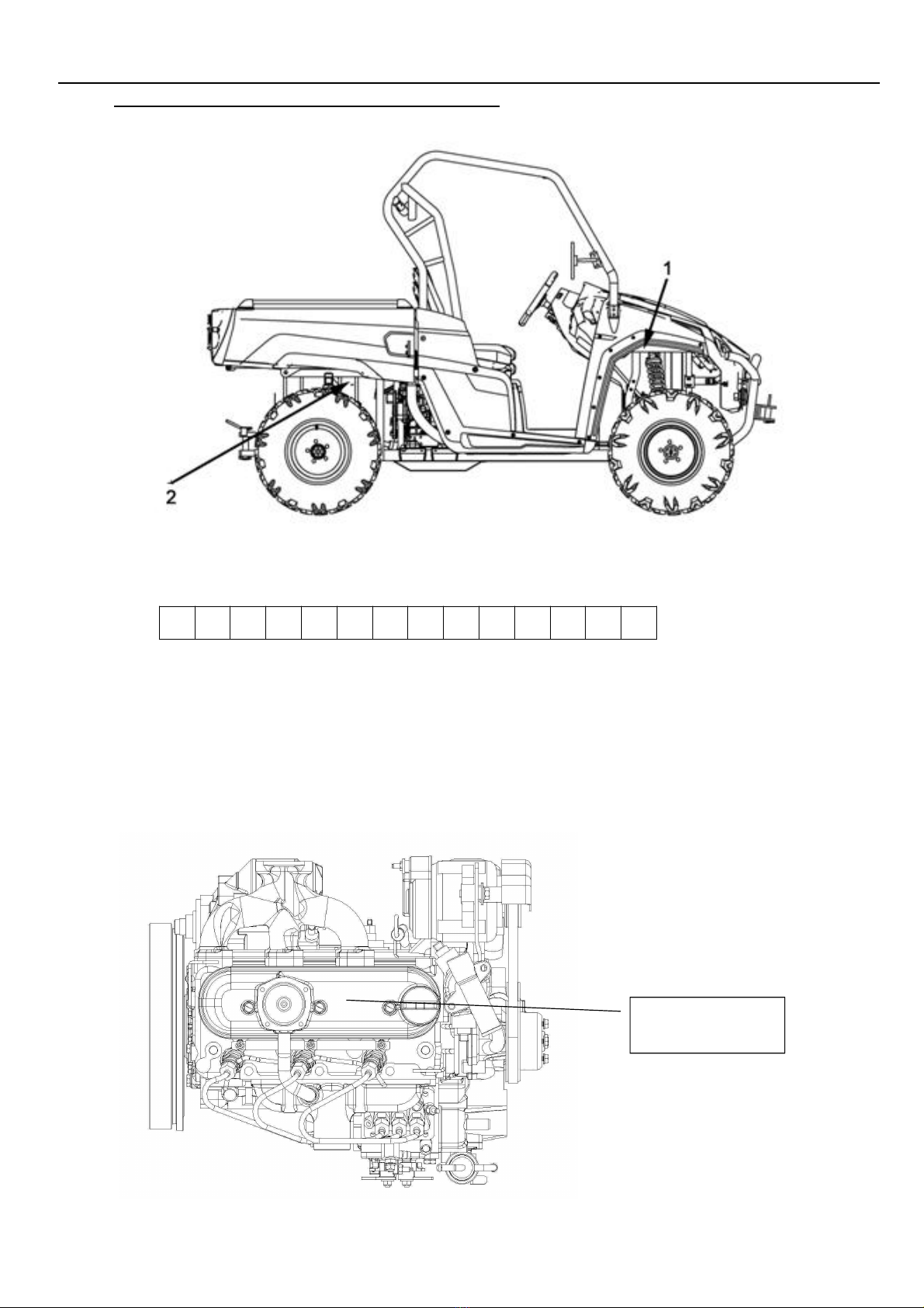
1.2 V.I.N AND ENGINE SERIAL NUMBER
Record the frame VIN and the engine serial number from your UTV in the spaces provided.
Frame VIN (found on the front right side of the frame tube)
The vehicle frame is important for model identification when registering your vehicle, obtaining
insurance or whenever replacement parts are required. In the event your vehicle were stolen these
numbers are essential to the recovery and identification of your UTV.
The engine serial numbers are punched on the surface of the crankcase
Engine number
CHAPTER 1 GENERALINFORMATION LH1100U-D SERVICE MANUAL 2019.0
CHAPTER 1 GENERAL PAGE. 1-
6
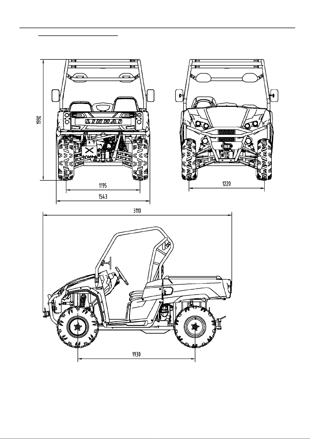
1.3 VEHICLE DIMENSIONS

CHAPTER 1 GENERALINFORMATION LH1100U-D SERVICE MANUAL 2019.0
CHAPTER 1 GENERAL PAGE. 1-
7
NOTES

CHAPTER 2 MAINTENANCE LH1100U-D SERVICE MANUAL 2019.0
CHAPTER 2 MAINTENANCE PAGE. 2-
1
CHAPTER 2 MAINTENANCE
The parts of different types/ variants/ versions maybe un-interchangeable, even some parts
have almost same appearance. Always refer to Parts Manual of each UTV model for spare
parts information and service.
2.1 PERIODIC MAINTENANCE
2.2 THROTTLE PEDAL INSPECTION
2.3 FUEL SYSTEM
2.4 TOE ALIGNMENT
2.5 BRAKING SYSTEM INSPECTION
2.6 SUSPENSION SPRING RPELOAD ADJ USTMENT
2.7 WHEELS
2.8 TIRE PRESSURE
2.9 FRAME, NUTS, BOLTS, FASTENERS
3.0 ST EERING COLUMN INSPECTION
CHAPTER 2 MAINTENANCE LH1100U-D SERVICE MANUAL 2019.0
CHAPTER 2 MAINTENANCE PAGE. 2-
2
2.1 PERIODIC MAINTENANCE
GENARAL
CAUTION
Mark on the following chart
D:Dueto the nature of the adjustments marked withaD on the following chart, it is
recommended thatservice be performed by an authorized dealer.
▲:Service/Inspect more frequently when operating in adverse conditions.
PERIODIC MAINTENANCE SCHEDULE
Careful periodic maintenance will help keep your vehicle in the safest, most reliable condition.
Inspection, adjustment and lubrication intervals of important components are explained in the
following chart on the following pages.
Maintenance intervals are based upon average riding conditions and an average vehicle
speed of approximately 16km/h (10 miles per hour). Vehicles subjected to severe use, such
as operation in wet or dusty areas, should be inspected and serviced more frequently.
Inspect, clean, lubricate, adjust or replace parts as necessary.
NOTE: Inspection may reveal the need forreplacement parts.Always use genuine parts
available from your dealer.
Serviceandadjustments are critical. If you are not familiar with safe service and adjustment
procedures, have a qualified dealer perform these operations.
Item
Hours
Calendar
Remarks
Brake System
—
Pre-ride
Pre-ride inspection item
Accelerator pedal
—
Pre-ride
Pre-ride inspection item
Fuel System
—
Pre-ride
Check for leaks at tankcap, lines, fuel
pump, filter
Tires
—
Pre-ride
Inspect daily, pre-rideinspection item
Front and Rear Wheels/
Hubs/Fasteners
—
Pre-ride
Pre-ride inspection item
D
Steering
—
Pre-ride
Inspect daily, lubricate
Frame nuts, bolts
fasteners
—
Pre-ride
Pre-ride inspection item
Front Suspension
—
Pre-ride
Pre-ride inspection item
Rear Suspension
—
Pre-ride
Pre-ride inspection item
Brake Fluid Level
—
Pre-ride
Pre-ride inspection item
Engine Oil Level
—
Pre-ride
Check Level Daily
Air Filter / Pre-Filter
Daily
Inspect; clean often
Air Box Sediment Tube
Daily
Drain deposits whenevervisible
CoolantLevel
Daily
Check level daily, replace engine
coolant every one year
Head Lamp / Tail Lamp
Daily
Check operation daily;apply dielectric
greaseto connector when replaced

CHAPTER 2 MAINTENANCE LH1100U-D SERVICE MANUAL 2019.0
CHAPTER 2 MAINTENANCE PAGE. 2-
3
Item
Hours
When
Remarks
Air Filter-Main Element
Weekly
Inspect ; Replace ifnecessary
D
Brake Pad Wear / Parking
Brake Pads
10 hrs
Monthly
Inspect periodically
D
Front and rear axle boots
10 hrs
Monthly
Checkfor Axle boots,
looseness,damage, replace if necessary
Battery
20 hrs
Monthly
Check/clean Terminals
Engine Cylinder Head and
Cylinder Base Fasteners
25 hrs
3 months
Inspect (re-torque required at first
service only)
Engine mounts
25 hrs
3 months
Inspect
General Lubrication
50 hrs
3 months
Lubricate all grease fittings,
pivots, cables, etc.
Shift Linkage
50 hrs
6 months
Inspect, adjust
Front Suspension
50 hrs
6 months
Inspect, lubricate,tighten fasteners
Rear Suspension
50 hrs
6 months
Inspect, lubricate,tighten fasteners
D
Steering
50 hrs
6 months
Check operation and for looseness,
worn, damage, binding feeling / Adjust,
repair, Replace if necessary.
Front Prop Shaft, Shaft Yoke,
Boots
50 hrs
6 months
Inspect, lubricate, replace if necessary
Rear Prop Shaft, Shaft Yoke,
Boots
50 hrs
6 months
Inspect, lubricate, replace if necessary
D
Throttle Cable/ Accelerator
pedal
50 hrs
6 months
Inspect, adjust, lubricate, replace if
necessary
D
Drive belt
50 hrs
6 months
Inspect, replace ifnecessary
Coolant strength
50 hrs
6 months
Inspect strength seasonally
Cooling System hoses
50 hrs
6 months
Inspect/replace ifnecessary
Rear Gear case Oil
100 hrs
Monthly
Check monthly and changeannually
Front Gear case Oil
100 hrs
Monthly
Check monthly and changeannually
Oil Filter
Every
100 hrs
2000 km or 6
months
Oil filter replacement at the above
intervals, should be done together with
the engine oil change
EngineOil-Level/Change
Every
100 hrs
2000 km or
6months
Check Level Daily; Break-in Service at
200Km (1month). Change oil more often
in cold weather use.
D
Parking Brake Cable
Adjustment
100 hrs
6 months
Inspect, adjust tension as needed
D
Fuel System
100 hrs
12 months
Check for leaks at tankcap, lines, fuel
pump, replace fuel lines annually
D
Wheels bearings
100 hrs
12 months
Inspect, replace if necessary
Radiator
100 hrs
12 months
Inspect, clean
D
Fuel Filter
100 hrs
12 months
Replace annually

CHAPTER 2 MAINTENANCE LH1100U-D SERVICE MANUAL 2019.0
CHAPTER 2 MAINTENANCE PAGE. 2-
4
Item
Hours
When
Remarks
Transmission Oil Level
100hrs
Monthly
Check monthly and changeannually
Spark Plug
100 hrs
12 months
Inspect-replace ifnecessary
Shock
100 hrs
Inspect seals
D
Brake Fluid
200 hrs
24 months
Change every tow years
Spark arrestor
300 hrs
36 months
Clean out, replace ifnecessary
D
Toe adjustment
As
required
As required
Periodic inspection,
adjust when parts are
replaced
Headlight Aim
As
required
As required
Adjust if necessary
LUBRICATION RECOMMENDATIONS
Item
Lube Rec
Method
Frequency
1.Engine Oil
API CH-4 SAE
15W-40
Add to properlevel on dipstick
Check level daily
2.Brake Fluid
DOT 3 Only
Maintain level between fill lines.
As require;
changeevery two
years or 200 hours
3.Rear Gear case oil
SAEGL-4 85W/90
Add to properlevel
Change annually orat
100 hours
4.Front Gear case oil
SAE GL-4 85W/90
Add to properlevel
Change annually or at
100 hours
5.Steering system
Grease
Lubricate the pivoting and sliding
parts
Every 3 months or50
hours
6.Tie rods
Grease
Grease
Semi-annually
7.ShiftLinkages
Grease
Locate fittingsand Grease
Semi-annually
8.Ball joints
Grease
Inspect, Locate fittingsand
Grease, or replace it if necessary
Semi-annually
9.Prop Shaft &Shaft
Yoke, Spline Joint
Grease
Locate fitting and Grease
Semi-annually or 50
hours
10.Front/RearA-arm
Grease
Locate fitting onpivot shaft
andgrease with grease gun
Semi-annually or 50
hours
11.ThrottleCable
Grease M
Grease, inspectand replace it
ifnecessary
Semi-annually or 50
hours
12.Acceleratorpedal
and brake pedal
Grease
Grease, inspect
Semi-annually or 50
hours
NOTE:
1. More often under severe use, such as wet or dusty conditions .
2. Grease: Light weight lithium-soap grease.
3. Grease M:molybdenum disulfide(MoS2) grease(water resistant).
4. *When suspension action becomes stiff or after washing.
5. Hours are based on 10 mph(16Km/h) average.

CHAPTER 2 MAINTENANCE LH1100U-D SERVICE MANUAL 2019.0
CHAPTER 2 MAINTENANCE PAGE. 2-
5
2.2 THROTTLEPEDAL INSPECTION
THROTTLE FREEPLAY
If the throttle pedal has excessive play due to cable
stretch or cable misadjustment, it will cause a delay
in throttle speed. Also, the throttle may not open fully.
If the throttle pedal has no play, the throttle may be
hard to control, and the idle speed may be erratic.
Check the throttle pedal play periodically in
accordance with the Periodic Maintenance Chart
and adjust the play if necessary.
THROTTLE FREEPLAY INSPECTION
1. Apply the parking brake.
2. Put the gear shift lever in the P(Park) position.
3. Start the engine, and warm it up thoroughly.
4. Measure the distance the throttle pedal moves
before the engine begins to pick up speed. Free
play should be 1.5 –3 mm.
Adjustment
1. Slide the boot off inline cable adjuster sleeve.
Loosen adjuster locknut.
2. Turn adjuster until 1.5 to 3 mm, freeplay is
achieved pedal. NOTE: While adjusting freeplay,
it is important you flip the throttle lever back and
forth.
3. Tighten locknut.
2.3 FUELSYSTEM
Always stop the engine and refuel outdoors or in a well ventilated area.
Do not smoke or allow open flames or sparks in or near the area where refueling is
performed or where gasoline is stored.
Do not overfill the tank. Do not fill the tank neck.
If you get fuel in your eyes or if you swallow gasoline, see your doctor immediately.
If you spill fuel on your skin or clothing, immediately wash it off with soap and water and
change clothing.
Never start the engine or let it run in an enclosed area. Fuel powered engine exhaust
fumes are poisonous and can cause loss of consciousness and death in a short time.
Never drain the float bowl when the engine is hot. Severe burns may result.

CHAPTER 2 MAINTENANCE LH1100U-D SERVICE MANUAL 2019.0
CHAPTER 2 MAINTENANCE PAGE. 2-
6
FUEL LINES
1. Check fuel lines for signsof wear,
deterioration, damage or leakage.
Replace if necessary.
2. Be sure fuel lines are routed
properly and secured with cable
ties.
CAUTION:
Make sure lines are not kinked
orpinched.
Replace all fuel lines every two years.
2.4TOEALIGNMENT
METHOD: STRAIGHTEDGE OR STRING
Be sure the steering wheel in astraight ahead position.
NOTE:Stringshould just touchside surfaceof reartire on
each sideof the UTV.
Measure from stringto rim at front andrear ofrim.
Rear rim measurement (A) should be 1/8" to 1/4" (3 to 6
mm) morethan front rimmeasurement (B).
Always pay attention to tie rods assembly, Both endsmust
screw in same and enough threads length.
2.5BRAKING SYSTEM INSPECTION
CHAPTER 2 MAINTENANCE LH1100U-D SERVICE MANUAL 2019.0
CHAPTER 2 MAINTENANCE PAGE. 2-
7
The following checks are recommended to keep the
braking system in good operating condition. Service
life of braking system componentsdepends on
operating conditions. Inspect brakes in accordance
with the maintenance schedule and before each ride
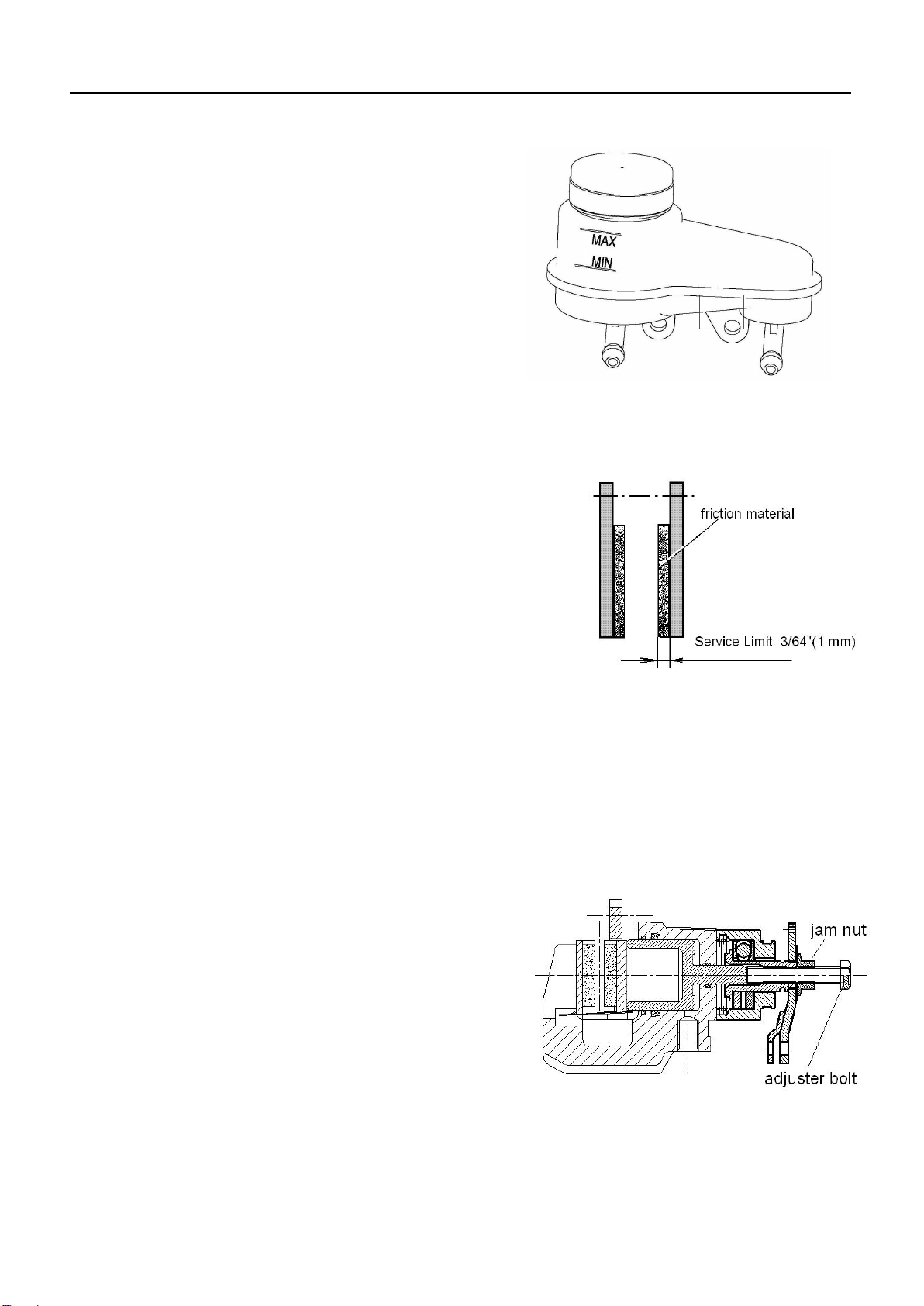
Keep fluid level in the master cylinder reservoirto
the indicated level on reservoir.
Use DOT 3 brake fluid.
NOTE: Use new brake fluid or brake fluid from a
sealed container to avoid contamination to system.
Check brake system for fluid leaks.
Check brake for excessive travel or spongy feel.
Check friction pads for wear, damage and looseness.
Check surface condition of the disc.
BRAKEPADINSPECTION
Pads should be changed when friction material is
worn to 3/64" (1mm).
HOSE/FITTINGINSPECTION
Check braking system hoses and fittings for cracks,
deterioration, abrasion, and leaks. Tighten any loose
fittings and replace any worn or damaged parts.
ADJUSTING THE BRAKE PEDAL
Check the brake pedal free play. Free play should be
8 –12mm. Outof specification →Adjust.
1. Loosen the locknut
2. Turn brake rod in or out until the correctfree play
is obtained.
3. Tighten the locknut
ADJUSTING THE PARKING BRAKE
Although the parking brake has beenadjusted at the
factory,the brake should be checked for proper
operation. Themechanical brake must be
maintained to be fullfunctional.
1. With the engine off, apply theparking brake lever
and attempt to move the UTV.
2. If the rear wheels are locked, it is adjusted
properly.
3. If thewheels are not locked, it must beadjusted.
To adjust (set up) the mechanical parking brake,
use thefollowing procedure

CHAPTER 2 MAINTENANCE LH1100U-D SERVICE MANUAL 2019.0
CHAPTER 2 MAINTENANCE PAGE. 2-
8
Note: The adjusting on the caliper is for the wear out
of the pads.
1. With the engine off, loosen the adjustor on the lever.
2. Loosen the jam nut of the adjuster on the caliper.
3. Turn the adjuster (bolt) CW (clockwise) by handtill the
pad touch the brake disc, turn the adjuster bolt CCW
(counterclockwise) by 1/4 to one turn for 10 to20mm
freeplay at the end of the parking lever.
4. Tighten the jam nuts securely against theadjusters.
5. Make sure the rear wheels turns freely without
dragging.
6. Turn the adjustor (the one on the lever) and apply the
lever. While adjusting,it is important you apply the
lever back and forthfor operation, free play and the
locking of the parking position.
7. Make sure the rear wheels turns freely without
dragging and parking brake works properly.
8. Field test for parking. It must be capable of holding
the laden UTV stationary on an 18% up and down
gradient.
A temporary adjusting can also be done to the brake
cable on the parking lever side by turn the adjuster
(nut) directly. But the adjust range is limited. Always do
the procedure 1 to 8 when necessary.
2.6SUSPENSION SPRING RPELOAD ADJUSTMENT
Operator weight and vehicle loading affect
suspensionspring preload requirements. Adjust as
necessary.
Compress and releasesuspension. Damping should
be smooth throughout the range of travel. Check
allsuspension componentsforwear or damage.
Inspect shockfor leakage
The front shock spring are adjustable. Rotate the
adjuster cam either direction to increase or decrease
spring tension. Always adjust both left and right sides
equally.
2.7 WHEELS
Inspect all wheels for runout of damage.
Check wheel nuts and ensure they are tight.

CHAPTER 2 MAINTENANCE LH1100U-D SERVICE MANUAL 2019.0
CHAPTER 2 MAINTENANCE PAGE. 2-
9
Do not over tighten the wheel nuts.
WHEEL REMOVAL
1. Stop the engine, place the transmission in gear and
lock the parking brake.
2. Loosen the wheel nuts slightly.
3. Elevate the side of the vehicle by placing a suitable
stand under the footrest frame.
4. Remove the wheel nuts and remove the wheel.
WHEEL INSTALLATION
1. With the transmission in gear and the parking
Brake locked, place the wheel in the correct
Position on the wheel hub. Be sure the valve
stem is toward the outside and rotation arrows
on the tire point toward rotation.
2. Attach the wheel nuts and finger tighten them.
Install as shown for front or rear wheels.
3. Lower the vehicle to the ground.
4. Securely tighten the wheel nuts to the proper
Torque listed in the table. On wheel nuts, Make
sure tapered end of nut goes into taper on
wheel.
Wheel Nut Torque Specifications
CAUTION:If wheels are improperly installed it could
affect Vehicle handling and tire wear.
2.8TIRE PRESSURE
TIRE INSPECTION
CAUTION:
Bolt Size
Specification
Front M12X1.25
69Ft.Lbs
95Nm
Rear M12X1.25
69Ft.Lbs
95Nm
CHAPTER 2 MAINTENANCE LH1100U-D SERVICE MANUAL 2019.0
CHAPTER 2 MAINTENANCE PAGE. 2-
10
Maintain proper tire pressure. Refer to the warning
tire pressure decal applied to the vehicle.
Improper tire inflation may affect UTV
maneuverability.
When replacing a tire always use original
equipment size and type and replace in pairs.
The use of non- standard size or type tires may
affect UTV handling and cause machine damage.
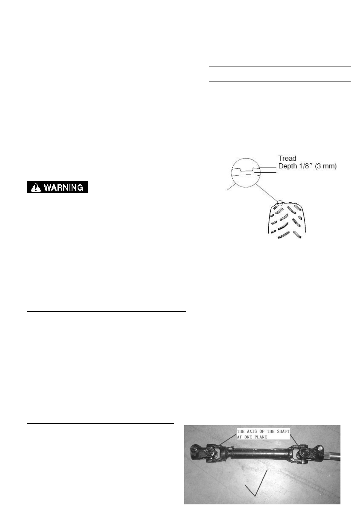
TIRE TREAD DEPTH
Always replace tires when tread depth is worn to 1/8"
(3mm ) or less.
Operating an UTV with worn tires will increase the
possibility of the vehicle skidding easily with possible
loss of control.
Worn tires can cause an accident.
Always replace tires when the tread depth measures
1/8" (3mm ) or less.
2.9FRAME , NUTS, BOLTS, FASTENERS
Periodically inspect the tightness of all fasteners in
accordance with the maintenance schedule. Check that
all cotter pins are in place. Refer to specific fastener
torques listed in each chapter.
3.0STEERING COLUMN INSPECTION
When assemble the steering column, check the
direction of the column.
Tire Pressure Inspection
Front
Rear
14PSI(97±0.5KPa)
14PSI(97±0.5KPa)
This manual suits for next models
1
Table of contents


