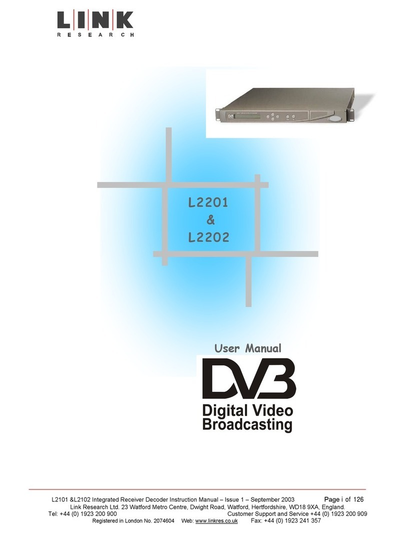
Link Research L2102 User manual

Link XP L2102/L2104 Receiver Instruction Manual Issue 1 - October 2003 Page 1 of 48
Link Research Ltd. 23/24 Watford Metro Centre, Dwight Road, Watford, Hertfordshire, WD18 9XA, England. Tel: +44 (0) 1923 200 900
Registered in London No. 2074604 Web: www.linkres.co.uk Fax: +44 (0) 1923 241 357
L2102 & L2104 Receiver
Instruction Manual
User Manual
L2102
&
L2104

Link XP L2102/L2104 Receiver Instruction Manual Issue 1 - October 2003 Page 2 of 48
Link Research Ltd. 23/24 Watford Metro Centre, Dwight Road, Watford, Hertfordshire, WD18 9XA, England. Tel: +44 (0) 1923 200 900
Registered in London No. 2074604 Web: www.linkres.co.uk Fax: +44 (0) 1923 241 357
L2102 & L2104 Receiver
Instruction Manual
Table of Contents
1. Firmware Versions Supported by this Manual.................................................. 4
2. About this manual ................................................................................. 4
3. Introduction ........................................................................................ 4
4. Warranty and support............................................................................. 5
4.1 Standard warranty cover................................................................ 5
4.2 Repair procedure ........................................................................ 5
4.3 Advance replacement service .......................................................... 5
5Safety, compliance and approvals .............................................................. 5
5.1 Safe Operating Procedures ............................................................. 5
5.2 Safety...................................................................................... 6
5.3 Radio....................................................................................... 6
5.4 CE Marking ................................................................................ 6
5.5 Other Compliance Notes ................................................................ 6
Section 1 – Getting Started and Basic Operation ................................................. 7
1.1 Getting Started ................................................................................. 7
1.1.1 Which model do I have? ................................................................. 7
1.1.2 Controls and connections ............................................................... 7
1.2 Getting Started – Plugging up the System................................................... 9
1.2.1 Controls and connections ............................................................... 9
1.2.2 Mounting the L3010...................................................................... 9
1.2.3 Setting the down convertor attenuation and local oscillator.................... 10
1.2.4 Non-diversity system .................................................................. 11
1.2.5 Diversity system........................................................................ 12
1.2.6 Dual diversity system.................................................................. 13
1.3 Turning on and setting up the receiver ................................................... 14
Section 2 – More Advanced Operation ........................................................... 21
2.1 Antennas....................................................................................... 21
2.1.1 The receive antenna .................................................................. 21
2.1.2 Diversity antennas ..................................................................... 22
2.1.3 LinkXP and other Manufacturers’ antennas ........................................ 23
2.1.4 Mounting antennas..................................................................... 23
2.1.5 A some practical examples ........................................................... 24
2.2 Cables.......................................................................................... 27
2.2.1 Why should I be concerned about cables?.......................................... 27
2.2.2 Cable impedances ..................................................................... 27
2.2.3 Cable losses............................................................................. 27
2.2.4 Cable types ............................................................................. 28
2.2.5 Care of cables .......................................................................... 29
2.3 The Receiver .................................................................................. 29
2.3.1 The Receiver Menu Structure ........................................................ 29
Section 3 - Technical Reference.................................................................. 38
3.1 Technical Specifications..................................................................... 38
L3010 Down-convertor .......................................................................... 38
Physical.................................................................................. 38
Mounting ................................................................................ 38
Environmental .......................................................................... 38
Power.................................................................................... 38
Lower Panel Connectors .............................................................. 38
Input ..................................................................................... 38
Output ................................................................................... 38
Input Signal Level ...................................................................... 38
Output Level............................................................................ 38
Spurious Outputs ....................................................................... 39
Inband Tones ........................................................................... 39
Frequency Stability .................................................................... 39
Phase Noise ............................................................................. 39

Link XP L2102/L2104 Receiver Instruction Manual Issue 1 - October 2003 Page 3 of 48
Link Research Ltd. 23/24 Watford Metro Centre, Dwight Road, Watford, Hertfordshire, WD18 9XA, England. Tel: +44 (0) 1923 200 900
Registered in London No. 2074604 Web: www.linkres.co.uk Fax: +44 (0) 1923 241 357
L2102 & L2104 Receiver
Instruction Manual
Down Conversion Factor .............................................................. 39
Down Conversion Attenuation........................................................ 39
L2102/L2104 Ultra Low Delay Integrated Receiver/Decoder.............................. 39
Physical.................................................................................. 39
Mounting ................................................................................ 39
Environmental .......................................................................... 39
Power.................................................................................... 39
Power Consumption ................................................................... 39
Front Panel Controls and Indicators................................................. 39
Rear Panel Connectors ................................................................ 40
Audio Output (option choice between 5 way XLR or 12-way connector block) 40
Video Outputs .......................................................................... 41
Video Inputs ............................................................................ 41
Analogue Audio Output ............................................................... 41
Input Signal Level ...................................................................... 41
3.2 Upgrading the unit ........................................................................... 42
3.2.1 Upgrading model types and options................................................. 42
3.2.2 Keeping track of current status...................................................... 42
3.2.3 Upgrade procedure. ................................................................... 43
3.3 Block diagrams ............................................................................ 47
3.3.1 L2102/L2104 Receiver block diagram ................................................. 47
3.3.2 L3010 Down convertor block diagram............................................... 48

Link XP L2102/L2104 Receiver Instruction Manual Issue 1 - October 2003 Page 4 of 48
Link Research Ltd. 23/24 Watford Metro Centre, Dwight Road, Watford, Hertfordshire, WD18 9XA, England. Tel: +44 (0) 1923 200 900
Registered in London No. 2074604 Web: www.linkres.co.uk Fax: +44 (0) 1923 241 357
L2102 & L2104 Receiver
Instruction Manual
1. Firmware Versions Supported by this Manual
The following firmware versions are supported by this manual:
•L2102/2104 Version 1.9
The latest firmware versions and details of how to download them can be found on the Link
Research web site:
www.linkres.co.uk
2. About this manual
This manual is divided into 3 sections:
•Section 1 – Getting started and basic operation. This will enable Users to set up
the system and get it running. A trouble-shooting guide is included.
•Section 2 – More advanced operation. This section gives detailed coverage of how
to change and store profiles including uploading/downloading files from a PC.
•Section 3 – Technical reference. This section is intended mainly for support
engineers and covers the system’s technical specifications and software upgrades.
3. Introduction
The Link Research L2102 and L2104 receivers are the first of a new generation of high
performance, low delay receivers. Designed for use with the LinkXP Wireless Camera
System or as a stand alone receiver it gives unrivalled performance in a very compact
footprint.
The system is very simple to set up using the front panel controls allowing rapid change of
frequency and system reconfiguration. In addition, the unit can be controlled by the hand-
held infra-red (IR) controller, L9020.
The internal design of the receivers is extremely compact using state-of-the-art
components and software giving a number of major advantages for the User.
•The low component count leaves few parts to go wrong giving very high
system reliability.
•All units in the system have been designed as part of an integrated family
ensuring the very best interoperability.
•The design is so flexible that the LinkXP wireless camera system gives
Customers the best future proofed product on the market today.
•Low power consumption ensures long operating times from each battery
before a change is needed.
•The very cool running temperature and careful component choice lead to a
product that is designed not to fail.
Link aim to make product backup second-to-none. Link has extensive manufacturing
experience as well as full servicing capability of both it’s own and many other
manufacturers’ products. The full Link product range is stocked leading to short lead times
and fast field support from the factory in Watford.
Always refer to the Link Research website, www.linkres.co.uk, for the latest information.
A customer section, password protected, is available in the Support Area. Please contact

Link XP L2102/L2104 Receiver Instruction Manual Issue 1 - October 2003 Page 5 of 48
Link Research Ltd. 23/24 Watford Metro Centre, Dwight Road, Watford, Hertfordshire, WD18 9XA, England. Tel: +44 (0) 1923 200 900
Registered in London No. 2074604 Web: www.linkres.co.uk Fax: +44 (0) 1923 241 357
L2102 & L2104 Receiver
Instruction Manual
Link Research to gain access to this area that gives access to the latest product news,
software upgrades etc..
4. Warranty and support
In all support requirements or in case of unit failure please contact Link directly (contact
details at the front of this manual). Always refer to the Link web site for firmware
upgrades, interoperability and support in general.
4.1 Standard warranty cover
L2102 and L2104 are fully covered for parts and labour in case of failure for one year from
date of despatch from Link Research Ltd.
In addition an advance replacement service is included for the first year, see below.
Extended warranty and advance replacement are available beyond the first year; contact
Link for details.
4.2 Repair procedure
If the unit has failed please contact Link to be given a RAN number (Return Authorisation
Number). Wherever possible please give a full description of the problem leading to the
failure.
Return the receiver to Link Research at the address given, preferably in the original
packaging and enclosing a full fault report wherever possible. The unit will be repaired and
returned as soon as possible. Repair times should be short but if you must have a
replacement unit immediately then you can take advantage of our advance replacement
service.
4.3 Advance replacement service
On request, once the fault has been discussed with a Link technician and a RAN number
allocated, Link will despatch a temporary replacement unit within 24 hours of your call.
The replacement unit must be returned on receipt of your repaired unit complete with the
original packaging.
N.B. For repairs and advance replacement units, shipping costs will be borne by Link for
the outward leg only.
For out-of-the box failures, occurring within the first 14 days from delivery, Link will
pay agreed transport costs in both directions.
5Safety, compliance and approvals
5.1 Safe Operating Procedures
The product must be earthed.
Ensure that the power requirements meet the L2102/L2104 specification.
Operate within the environmental limits of the product and ensure there is
adequate ventilation. Units can be mounted one above the other without
compromising heat dissipation, but allow at least 40mm free air-space at each side
of the equipment.

Link XP L2102/L2104 Receiver Instruction Manual Issue 1 - October 2003 Page 6 of 48
Link Research Ltd. 23/24 Watford Metro Centre, Dwight Road, Watford, Hertfordshire, WD18 9XA, England. Tel: +44 (0) 1923 200 900
Registered in London No. 2074604 Web: www.linkres.co.uk Fax: +44 (0) 1923 241 357
L2102 & L2104 Receiver
Instruction Manual
Do not subject the equipment to splashing or dripping liquids.
Only authorised trained personnel should open the product. There are no functions
that require the User to gain access to the interior of the product.
5.2 Safety
This equipment has been designed to meet the requirements of the following:-
EN60950 European Safety of information technology equipment including
business equipment.
IEC 60950 International Safety of information technology
equipment including business equipment.
UL 1950USA Safety of information technology equipment including
business equipment.
The equipment has been designed to meet the following:-
EN 55022 European Emission Standard equipment-class A.
EN 55103-2 European Generic Immunity Standard.
FCC USA Conducted and radiated emission limits
For a Class A digital device
ETSI EN301 - 489 - 3 For Radio Equipment in the range of 1GHz to
40GHz.
5.3 Radio
ETSI EN300 - 440 -1 For Radio Equipment in the range of 1 GHz to
40GHz
5.4 CE Marking
The CE mark is affixed to the LinkXP and the EC Declaration of Conformity and the
Technical File is available on request.
5.5 Other Compliance Notes
Antistatic precautions should be observed when connecting leads to the rear panel
connectors.
Nominal lead length used for EMC checks was less than 3 metres.

Link XP L2102/L2104 Receiver Instruction Manual Issue 1 - October 2003 Page 7 of 48
Link Research Ltd. 23/24 Watford Metro Centre, Dwight Road, Watford, Hertfordshire, WD18 9XA, England. Tel: +44 (0) 1923 200 900
Registered in London No. 2074604 Web: www.linkres.co.uk Fax: +44 (0) 1923 241 357
L2102 & L2104 Receiver
Instruction Manual
Section 1 – Getting Started and
Basic Operation
1.1 Getting Started
1.1.1 Which model do I have?
L2102 has two F-type RF inputs on the rear whereas L2104 has four. Mains powered
versions have a three-pin IEC mains inlet socket: DC powered versions have a 4-pin XLR
input plug.
1.1.2 Controls and connections
STATUS
ALARM
POWER
L2100 DIVERSITY IRD - Ultra Low Delay
CJM2 Technology
Figure 1 – Controls and displays – L2102 and L2104
Control/Display Function
Enter button Allows downward navigation of the menu system
Stores system parameters after they have been set
Exit button Allows upward navigation of the menu system
Cancels any parameter changes made restoring the
previously stored value
Up button Allows upward navigation in a sub menu.
Down button Allows downward navigation in a sub menu.
Left button Returns the user to a higher-level menu and allows
movement to the left when changing parameters within a
menu setting.
Right button Allows movement to the right when changing parameters
within a menu setting.
LCD window Displays menu settings and system status
IR window Allows receiver set-up using remote infra red controller
Status LED (yellow) When lit, the receiver is locked to a signal.
Alarm LED (red) When lit, an alarm has been detected. For details enter
the alarm menu.
Power LED (green) When lit, power is applied to the receiver.
Left
button
Enter
button
LED indicators
Up button
Liquid crystal
display
IR remote control
sensor Exit button
Down
button
Right
button

Link XP L2102/L2104 Receiver Instruction Manual Issue 1 - October 2003 Page 8 of 48
Link Research Ltd. 23/24 Watford Metro Centre, Dwight Road, Watford, Hertfordshire, WD18 9XA, England. Tel: +44 (0) 1923 200 900
Registered in London No. 2074604 Web: www.linkres.co.uk Fax: +44 (0) 1923 241 357
L2102 & L2104 Receiver
Instruction Manual
Figure 2 – L2102 rear panel connections AC powered
ASI out
Remote/Alarm/DataVIDEO
SDI RF1
RF2
100/240V
50/60Hz
1A ~
FUSE
T1.6A
240V
RF3
RF4
F/LOCKAUDIO 1 AUDIO 2
Figure 3 – L2104 rear panel connections AC powered
Connector type Legend Description
F-type 75Ωthreaded
socket
RF1 & RF2
RF3 & RF4
RF input from L3010 down convertor
Power output for L3010
22kHz tone output for control of L3010
9-way D-sub socket Remote/Alarm/Data RS232 remote control port
Alarm signalling, firmware upgrade
BNC 75Ωbayonet
socket
ASI out ASI transport stream output
BNC 75Ωbayonet
socket
Video Video output
BNC 75Ωbayonet
socket
Frame lock Delays the output signal by up to 40ms
to lock the video frames to an external
reference.
NB – colour sub carrier is not locked.
BNC 75Ωbayonet
socket
SDI SDI output.
5-way XLR Audio 1 & Audio 2 Two audio stereo pairs or 4 mono
channels outputs or 2 digital audio
outputs
IEC socket* Mains 110 –220VAC Mains power input
4-way XLR panel
mounted plug*
DC in DC power input 9VDC – 32VDC
* Standard configuration is for IEC mains input. The DC input is optional and replaces the
IEC socket.

Link XP L2102/L2104 Receiver Instruction Manual Issue 1 - October 2003 Page 9 of 48
Link Research Ltd. 23/24 Watford Metro Centre, Dwight Road, Watford, Hertfordshire, WD18 9XA, England. Tel: +44 (0) 1923 200 900
Registered in London No. 2074604 Web: www.linkres.co.uk Fax: +44 (0) 1923 241 357
L2102 & L2104 Receiver
Instruction Manual
1.2 Getting Started – Plugging up the System
1.2.1 Controls and connections
Figure 4 – L3010 connections
Two connections are provided on the lower side of the unit as shown in the table below.
Connector type Legend Description
F-type 75Ωthreaded
socket
Not marked UHF intermediate frequency out to
receiver
Power input to down convertor from
receiver.
N-type 50Ωthreaded
socket
Not marked SHF input from antenna
Red LED Not marked Indicates the down convertor is receiving
power from the receiver.
1.2.2 Mounting the L3010
The L3010 down convertor should be mounted so that the two connectors are facing
downwards. This will help to prevent water ingress. In areas of very heavy rainfall the
L3010 should be mounted inside a waterproof protective cover.
The L3010 must be mounted as close to the receive antenna as possible with a maximum
cable length between antenna and down convertor of 1 metre. When using Link Research
antennas N-type elbows are used to keep the feed length to a minimum.
For temporary installations, cable ties can be threaded through the holes in the corners of
the pole bracket and then tied to any convenient point. It is worth remembering that
although the L3010 is very light, the support must be capable of taking the combined
weight of the L3010 and the drop cable to the receiver unless this is independently
supported.
The L3010 is supplied with a specially shaped plate for mouning on either horizontal or
vertical poles with U bolts or tie wraps. Alternatively for permanent installations, the
L3010 can be mounted directly onto a flat surface using screws through the casing holes in
each corner.

Link XP L2102/L2104 Receiver Instruction Manual Issue 1 - October 2003 Page 10 of 48
Link Research Ltd. 23/24 Watford Metro Centre, Dwight Road, Watford, Hertfordshire, WD18 9XA, England. Tel: +44 (0) 1923 200 900
Registered in London No. 2074604 Web: www.linkres.co.uk Fax: +44 (0) 1923 241 357
L2102 & L2104 Receiver
Instruction Manual
1.2.3 Setting the down convertor attenuation and local
oscillator
Normally, the down convertor gain is preset to a setting chosen for most applications. If
the receiver appears to be overloaded or performance is unsatisfactory, it may be
necessary to alter the setting. To do this it is necessary to open the down convertor casing
by removing the two screws along the top edge.
Once the cover is lifted off, all the switches are freely accessible.
It is not recommended that the attenuation settings for 30dB and 40dB (3 LEDs lit and
no LEDs lit) are used as this has the effect of significantly reducing the signal to noise
ratio.
Switch settings are as follows:
Switch Default setting Description
Gain setting switch S1 Last setting Changes the down convertor
attenuation
Hi/Lo switch S2 Hi (when lit) Selects local oscillator to be
used by the system.
Set to Hi for 2.3 to 2.7GHz
Set to Lo for 1.95 to 2.3GHz
ID switch S3 and S4 User selectable Not currently used
The local oscillator frequency will need to be set to match the correct frequency band.
For frequencies between 1.95GHz and 2.3GHz, set the oscillator in the Lo position (LED not
lit). For frequencies between 2.3GHz and 2.7GHz set the oscillator in the Hi position (LED
lit). This is the default position.
Care needs to be exercised when setting the down convertor attenuation. The main
purpose of the attenuation is to compensate for drop lead cable length, but if incorrectly
set, the attenuation will have an adverse effect on the noise performance and range of the
Hi oscillator
running LED
Attenuation indicating LEDs
3 lit = 30dB attenuation
2 lit = 20dB attenuation
1 lit = 10dB attenuation
0 lit = 40dB attenuation
Address
switches
S3 & S4
Hi/Lo select
switch S2
Gain setting
switch S1
Figure 5
– switches and LEDs
inside down convertor

Link XP L2102/L2104 Receiver Instruction Manual Issue 1 - October 2003 Page 11 of 48
Link Research Ltd. 23/24 Watford Metro Centre, Dwight Road, Watford, Hertfordshire, WD18 9XA, England. Tel: +44 (0) 1923 200 900
Registered in London No. 2074604 Web: www.linkres.co.uk Fax: +44 (0) 1923 241 357
L2102 & L2104 Receiver
Instruction Manual
system. Briefly, with one LED lit, 10dB of attenuation is introduced to protect the front
end of the receiver with reasonably long cable lengths. There is very little difference in
the noise performance of the system. Turning on two LEDs introduces 20dB do attenuation
which will protect the receiver front end with medium cable lengths. The noise
performance is increased slightly and the range of the system may be reduced by up to 30%.
With 3 LEDs switched on 30dB of attenuation is introduced and should only be used for very
short cable lengths. The noise performance of the system can be seriously degraded and
the range reduced by up to 75%. With no LEDs lit, there is no attenuation and this
condition should only be used for very long cables or where the signal is very weak. The
receiver front end has no protection with this setting.
1.2.4 Non-diversity system
This is the simplest system and the receive side only requires 1 antenna and down convertor
to make it work. The performance over short distances will be good, but not as good as a 2
channel diversity system. For outdoor installations where only a small area has to be
covered, non-diversity is ideal.
Generally the antenna should be placed as high as possible and in the clear. See section 2
on antennas for more information.
Connect the receiver as shown in the diagram below. Take care to keep all cables away
from potential sources of interference and/or damage (see section on cables for more
information).
NB When connecting up the cables the receiver should not be powered up. The LNB power
may be active whilst cables are being connected and it is easy to make a short circuit. It is
very unlikely that any damage will be done because the LNB power supply is short circuit
protected, but it is better to be safe than sorry!

Link XP L2102/L2104 Receiver Instruction Manual Issue 1 - October 2003 Page 12 of 48
Link Research Ltd. 23/24 Watford Metro Centre, Dwight Road, Watford, Hertfordshire, WD18 9XA, England. Tel: +44 (0) 1923 200 900
Registered in London No. 2074604 Web: www.linkres.co.uk Fax: +44 (0) 1923 241 357
L2102 & L2104 Receiver
Instruction Manual
Audio
Frame
Lock
RF1
RF2
AC Mains
SDI
Video
ASI
Receive antenna
L3010 Down
convertor
75 ohm downlead
Mast
L2102 receiver
Figure 6 – Non-diversity system
Outputs from the receiver can be taken from SDI out or video out or both and audio from
the mulitway connector block or 5 way XLR connector depending on the option fitted. If
required, Frame Lock can be connected to synchronise the output with other equipment.
NB – the colour sub carrier is not locked.
1.2.5 Diversity system
This is a much more robust system giving better performance than non-diversity especially
when the installation is indoors. The transmission range is not increased very much, but
performance near the margins of the transmission area is much more robust and RF “black
holes” are eliminated.
Generally the antennas should be placed as high as possible and in the clear (see section 2
on antennas for more information). The antenna spacing is fairly critical and should be
around 20cm to gain optimum performance. If a greater spacing than 20cm is used, the
full benefits of diversity will not be obtained. A little experimentation may be needed to
find the optimum spacing in a particular environment.
Connect the receive side as shown in the diagram below. Take care to keep all cables away
from potential sources of interference and/or damage (see the section on cables for more
information).
NB When connecting up the cables the receiver should not be powered up. The LNB power
may be active whilst cables are being connected and it is easy to make a short circuit. It is

Link XP L2102/L2104 Receiver Instruction Manual Issue 1 - October 2003 Page 13 of 48
Link Research Ltd. 23/24 Watford Metro Centre, Dwight Road, Watford, Hertfordshire, WD18 9XA, England. Tel: +44 (0) 1923 200 900
Registered in London No. 2074604 Web: www.linkres.co.uk Fax: +44 (0) 1923 241 357
L2102 & L2104 Receiver
Instruction Manual
very unlikely that any damage will be done because the LNB power supply is short circuit
protected, but it is better to be safe than sorry!
Connect the receiver as follows:
Audio
RF1
RF2
AC Mains
SDI
Video
Receive
antenna
L3010 Down
convertor
75 ohm
downlead
Mast
Crossbar
L2102 receiver
75 ohm
downlead
L3010 Down
convertor
Receive
antenna
20 - 100cm spacing
Figure 7 – Diversity system
Outputs from the receiver can be taken from SDI out or video out or both and audio from
the mulitway connector block or 5 way XLR depending on which option is fitted. If required,
a synchronising signal can be input to Frame Lock to synchronise the output with other
equipment.
1.2.6 Dual diversity system
Dual diversity can be used in two different ways. If all four demodulators are set to the
same frequency, one receiver can be used to cover a much greater area. The system could
be set up so that one pair of antennas is inside a stadium covering a sports pitch and the
other pair of antennas is outside the stadium covering the entrances. A single transmitter
can then be used to cover the arrival of a sports team and their entry to the stadium using

Link XP L2102/L2104 Receiver Instruction Manual Issue 1 - October 2003 Page 14 of 48
Link Research Ltd. 23/24 Watford Metro Centre, Dwight Road, Watford, Hertfordshire, WD18 9XA, England. Tel: +44 (0) 1923 200 900
Registered in London No. 2074604 Web: www.linkres.co.uk Fax: +44 (0) 1923 241 357
L2102 & L2104 Receiver
Instruction Manual
the outside antennas and then cover the match using the inside antennas. Movement from
one antenna coverage area to the other will be seamless.
The second way of using dual diversity is to set demodulators 1 and 2 to one frequency and
demodulators 3 and 4 to a second frequency. The system can now be used with two
different camera transmitters. Each camera transmitter will need to have a different
service name (see protocol command list type m) set so that the receiver can select
between them. In this way, it is possible to choose which camera will provide the
receiver’s output. Switching between transmitters will not be seamless as there will be
some disturbance as the source is changed.
Generally the antennas should be placed as high as possible and in the clear (see section xx
on antennas for more information). The antenna spacing is fairly critical and should be
around 20cm to gain optimum performance. If a greater spacing than 20cm is used, the
full benefits of diversity will not be obtained. A little experimentation may be needed to
find the optimum spacing in a particular environment.
Connect the receiver as shown in the diagram below. Take care to keep all cables away
from potential sources of interference and/or damage (see the section on cables for more
information).
NB When connecting up the cables the receiver should not be powered up. The LNB power
may be active whilst cables are being connected and it is easy to make a short circuit. It is
very unlikely that any damage will be done because the LNB power supply is short circuit
protected, but it is better to be safe than sorry!
Audio
RF4
RF1
RF2
AC Mains
SDI
Video
RF3
Receive
antenna
L3010 Down
convertor
75 ohm
downlead
Mast
Crossbar
L2104 receiver
75 ohm
downlead
L3010 Down
convertor
Receive
antenna
20 - 100cm spacing
Receive
antenna
L3010 Down
convertor
75 ohm
downlead
Mast
Crossbar
75 ohm
downlead
L3010 Down
convertor
Receive
antenna
20 - 100cm spacing
1.3 Turning on and setting up the receiver
Fig 8
– dual diversity
system

Link XP L2102/L2104 Receiver Instruction Manual Issue 1 - October 2003 Page 15 of 48
Link Research Ltd. 23/24 Watford Metro Centre, Dwight Road, Watford, Hertfordshire, WD18 9XA, England. Tel: +44 (0) 1923 200 900
Registered in London No. 2074604 Web: www.linkres.co.uk Fax: +44 (0) 1923 241 357
L2102 & L2104 Receiver
Instruction Manual
There is no ON/OFF switch, so plugging in the power cable will turn the receiver on. NB;
connect the antenna cable(s) and L3010(s) before turning the unit on.
Once the unit has booted up, the display screen will look something like the illustration
below.
Figure 9 - top-level menu screen just after boot up
If a valid input signal is present, the amber STATUS indicator will light: if there is no valid
input signal, the red ALARM indicator will be lit.
To enter the menu system, press the button nearest the bottom right corner of the display.
The display will now look something like the illustration below.
Status
LNB ON
Figure 10 - Status menu top level
Press the down arrow until the down unit menu is shown and press enter to select it. Press
the down arrow until the down convertor type menu is displayed. The display will look
something like that shown below.
DConv Type None
Figure 11- down convertor type menu
Pressing the enter key, , allows access to the following options:
•L3010
•Other
•None
Select according to the type of down covertor to be used with the system. Once selected
and confirmed with the enter key, , the display will change to indicate the type
selected.
Now go back up the menu until the diversity setting menu is displayed.

Link XP L2102/L2104 Receiver Instruction Manual Issue 1 - October 2003 Page 16 of 48
Link Research Ltd. 23/24 Watford Metro Centre, Dwight Road, Watford, Hertfordshire, WD18 9XA, England. Tel: +44 (0) 1923 200 900
Registered in London No. 2074604 Web: www.linkres.co.uk Fax: +44 (0) 1923 241 357
L2102 & L2104 Receiver
Instruction Manual
Mode Diversity
LNB ON
Pressing the enter key, , provides a sub menu with the following options:
•Single
•Diversity
•Dual Diversity
•Remux
•Bypass 1
•Bypass 2
•Bypass 3
•Bypass 4
•Test
To select the required option, press the enter key, , when the option name is displayed
in the window. Then press the exit key, , to return to the upper level.
If a down convertor other than an L3010 has been selected, it will be necessary to go to the
down convertor local oscillator set up page. The display should look something like the
illustration below.
DConvLO 1.8400GHz
LNB ON
To change the local oscillator setting, press the enter key and change to the new
value. Press the enter key again to store the new setting and then press the escape key
to return to the Demodulator 1 menu.
NB. It is not possible to use down convertors of mixed manufacture in a diversity
system. The only way this can be done is to select “single” and different local
oscillator values can be entered.
Next, the Input Frequency must be set. At the Demodulator 1 menu, press enter and the
Input Frequency page will be shown and will look something like the illustration below.
- > 2.3950(GHz)
Figure 14 - Frequency changing display
Figure 12 - Dive
r
sity setting
menu
Figure 13 - Down convertor
status screen (shown for L3010)

Link XP L2102/L2104 Receiver Instruction Manual Issue 1 - October 2003 Page 17 of 48
Link Research Ltd. 23/24 Watford Metro Centre, Dwight Road, Watford, Hertfordshire, WD18 9XA, England. Tel: +44 (0) 1923 200 900
Registered in London No. 2074604 Web: www.linkres.co.uk Fax: +44 (0) 1923 241 357
L2102 & L2104 Receiver
Instruction Manual
To change the frequency, use the right button to move the block cursor over the number
to be changed and then use the up or down arrows to scroll through the numbers until the
required number appears. To accept and start using the changes, press the enter key .
To reject the changes and go back to the top of the frequency menu, press the escape key
.
If the unit is working in Diversity mode, it is not necessary to make settings for
Demodulator 2 as these are automatically carried forward from the Demodulator 1 menu.
When setting up an L2104, it will be necessary to repeat the frequency selection steps
detailed above for demodulator 3. Demodulator 4 will “follow” the settings made in
demodulator 3.
Next, use the down arrow key to select the LNB power menu. The display will look
something like the illustration below.
LNB Power No
Figure 15 – LNB Power Screen
Pressing enter allows two selections to be made:
•Yes
•No
Select the required status by pressing enter, , and the display will be updated to
indicate the status.
When the LNB power is set to on, an LED between the two connectors on the L3010 will be
lit indicating the down convertor is powered (early down convertors do not have this LED
fitted).
The unit should now be locked to the incoming signal. If it is not, go back and check the
settings made above.
Next go to the Decoder menu.
The screen will look something like the illustration below.
Decoder
Figure 16 - Decoder screen

Link XP L2102/L2104 Receiver Instruction Manual Issue 1 - October 2003 Page 18 of 48
Link Research Ltd. 23/24 Watford Metro Centre, Dwight Road, Watford, Hertfordshire, WD18 9XA, England. Tel: +44 (0) 1923 200 900
Registered in London No. 2074604 Web: www.linkres.co.uk Fax: +44 (0) 1923 241 357
L2102 & L2104 Receiver
Instruction Manual
Use the down arrow key until a list of available services is displayed and select the required
service. Press the enter key to confirm the selection.
Now go to the Audio A menu where the current status will be shown and may look
something like the illustration below.
Aaudio O/P Ana
Figure 17 - Channel A audio status
In the illustration above the status is analogue. To change this to digital, press the enter
button, , select digital and confirm the selection by pressing enter again.
Channel B audio is set up in the say way from the Baudio O/P menu.
If the signal being received is scrambled, it will be necessary to set up the descrambling
menu. To do this select the descrambling menu (6 down arrow presses from Status) and a
screen like the illustration below will be shown.
Figure 18 – Descrambling screen
By using the up or down arrow the following options are available:
•Descrambling Off
•EBS Key “
If EBS Key “ is selected one of the following screens will be displayed:
- >
- > / / / / / / /
Figure 19 – EBS key change screens
The EBS key is an 8 digit hexadecimal number. To enter it, use the up arrow to scroll
through the numbers 1 – 9 and letters A – F. Once the required character has been
selected, use the right arrow key to move the cursor to the next position. Repeat the
Screen when no previous
EBS key has been entered
Screen when a previous
EBS key has been entered

Link XP L2102/L2104 Receiver Instruction Manual Issue 1 - October 2003 Page 19 of 48
Link Research Ltd. 23/24 Watford Metro Centre, Dwight Road, Watford, Hertfordshire, WD18 9XA, England. Tel: +44 (0) 1923 200 900
Registered in London No. 2074604 Web: www.linkres.co.uk Fax: +44 (0) 1923 241 357
L2102 & L2104 Receiver
Instruction Manual
selection process until the next character is shown. Once the complete key is displayed,
press the enter key, , to store this in memory.
NB. It is possible to select characters outside the range of 1 – 9 and A – F, but such a
selection will be rejected when the enter key is pressed.
Once the receiver is set up, go to the Status menu and press enter, , and a screen like
the illustration below will be displayed.
Figure 20 – Signal quality status display (L2102)
The bar graphs give an indication of the relative signal quality of the decoded MPEG
packets. In operation it is quite normal that the bar graphs fluctuate wildly.
If the receiver is to be powered off, the settings will be retained in the current memory.
When powered up again, it will use these settings unless another memory is recalled to the
current memory. It is therefore good practice to save the set up to one of the nine
memories so that it can be recalled easily. To do this, enter the Memory menu (one down
from Status). The top-level screen will look something like the illustration below:
Memory
Figure 21 – Memory menu top level
Press the enter key and the screen display will change:
Store - Config ?
Figure 22 - Store config screen
Press the enter key and the screen will change again to:
->Config ?
Figure 23 – Second level of storing a configuration

Link XP L2102/L2104 Receiver Instruction Manual Issue 1 - October 2003 Page 20 of 48
Link Research Ltd. 23/24 Watford Metro Centre, Dwight Road, Watford, Hertfordshire, WD18 9XA, England. Tel: +44 (0) 1923 200 900
Registered in London No. 2074604 Web: www.linkres.co.uk Fax: +44 (0) 1923 241 357
L2102 & L2104 Receiver
Instruction Manual
Pressing the down arrow scrolls through the numbers 1 – 9 and the up arrow 9 – 1. Once the
desired memory is selected, press the enter key and all the settings will be stored for easy
recall.
To recall a previously stored configuration, go to the Memory menu, press enter and then
use the down arrow to select the Load config option. The screen will look something like
the illustration below:
Load - Config ?
Figure 24 – The load config screen
Press enter and the display will change to something like the illustration below:
->Config ?
Figure 25 - Configuration selection screen
By using the down arrow, memory locations from 1 – 9 can be selected. Using the up arrow
allows memory location selection from 9 – 1. Once the desired memory has been selected,
pressing, , will store the setup data in that location.
This manual suits for next models
1
Table of contents
Other Link Research Receiver manuals
