Winradio WR-ETC-100 User guide

WiNRADiO®
WR-ETC-100
(for the G35DDCi)
Multichannel Coherent Application Guide for the
Extended Topology Configuration option (ETC)
Version 1.0

WR-G35DDCi Multichannel Coherent Application Guide for Extended topology configuration (ETC)
2
Table of contents
Introduction ........................................................................................................................... 4
2. Parts description of the coherent system........................................................................... 6
2.1 WR-G35DDCi connectors............................................................................................ 6
2.2 The WiNRADiO Coherence Clock & 1PPS Kit (WR-CC1PPS-100).............................. 7
2.2.1 Coherent clock generator board ............................................................................ 8
2.2.2 PCIe connector...................................................................................................... 9
2.2.3 SMA connectors for sampling clock output............................................................ 9
2.2.4 Digital synchronization interface............................................................................ 9
2.2.5 Frequency reference output REF OUT.................................................................10
2.2.6 Frequency reference input REF IN.......................................................................10
2.2.7 1PPS trigger input ................................................................................................10
2.2.8 Locked indicator...................................................................................................10
2.2.9 SMA patch cables for Coherent clock distribution.................................................11
2.2.10 Digital synchronization cables for each WR-G35DDCi receiver..........................11
2.2.11 Digital synchronization cable for the Coherent clock generator board.................12
2.2.12 Frequency reference SMA interconnect cable ....................................................12
2.2.13 SMA terminators.................................................................................................13
2.2.14 Sampling clock oscillator input and outputs ........................................................14
2.2.15 SMA jumper cable..............................................................................................14
2.2.16 Pin header for disabling the sampling clock oscillator.........................................15
2.3 The WiNRADiO ETC kit (WR-ETC-100)......................................................................16
2.3.1 ETC kit board .......................................................................................................17
2.3.2 PCIe connector.....................................................................................................18
2.3.3 SMA connector SYNC IN......................................................................................18
2.3.4 SMA connector SYNC OUT..................................................................................18
2.3.5 Digital synchronization interface...........................................................................18
2.3.6 SMA adapter for the sampling clock.....................................................................19

WR-G35DDCi Multichannel Coherent Application Guide for Extended topology configuration (ETC)
3
2.3.7 Digital synchronization cable for ETC board.........................................................19
2.3.8 30 cm SMA sampling clock patch cable................................................................19
2.3.9 SMA coaxial cables for the sampling clock and synchronization...........................20
2.4 The WiNRADiO PCIe Bracket Multi-SMA Adapter.......................................................22
3. ETC installation of up to eight receivers............................................................................23
3.1 Preparing the receivers for installation into a PC.........................................................26
3.2 Installing the receiver into a PC...................................................................................28
3.3 Installing the ETC board into the PC...........................................................................29
3.4 Interconnecting the Coherent Clock Generator board .................................................31
3.5 Installing the Coherent clock generator board into the PC...........................................32
3.6 Choosing the frequency reference ..............................................................................35
3.7 Connecting the CLOCK interconnection......................................................................36
3.8 Connecting the SYNC interconnection........................................................................37
3.9 Connecting the 1PPS signal........................................................................................39
3.10 Power up and driver installation ................................................................................39
4. Extended installation of up to sixteen receivers................................................................40
4.1 Connecting two Coherent clock generator boards.......................................................40
4.2 Installation of receivers................................................................................................42
5. Technical specification .....................................................................................................44
6. Contacts...........................................................................................................................45

WR-G35DDCi Multichannel Coherent Application Guide for Extended topology configuration (ETC)
4
Introduction
The WiNRADiO WR-G35DDCi receiver optionally provides multichannel coherent operation.
A minimum of two and up to sixteen receivers can be coupled together for multichannel
operation.
This document does not describe the standard installation of WR-G35DDCi receivers for
multichannel coherent operation. The standard installation of the WR-G35DDCi receivers in
coherent mode requires all WR-G35DDCi receivers to be installed inside the same PC and
all connections between receivers and other supportive hardware are realized internally,
within the same PC. For standard installation please refer to WR-G35DDCi Multichannel
Coherent Application Guide.
This document describes non-standard, Extended Topology Configuration (ETC) for
multichannel coherent operation of the WR-G35DDCi receivers, which allows the receivers to
be installed in multiple PCs. Typically, each WR-G35DDCi receiver is installed in a separate
dedicated PC. Installation of multiple receivers inside the same PC is allowed in the ETC
configuration, however any receivers installed inside the same PC act the same way as they
would, when installed in separate dedicated PCs. In other words, each receiver has to run its
own instance of software. Also, it is not possible to mix the standard installation with the ETC
installation. All necessary connections between the receivers and other supportive hardware
are realized externally, outside of the PCs.
To couple up to eight receivers, the WR-CC1PPS-100 ‘WiNRADiO WR-G35DDCi Coherence
Clock & 1PPS Kit’ (the Clock Kit) has to be used, which is described in Section 2.2.
To couple from nine to sixteen receivers, two Clock Kits have to be used. For more than
sixteen channels please contact WiNRADiO.
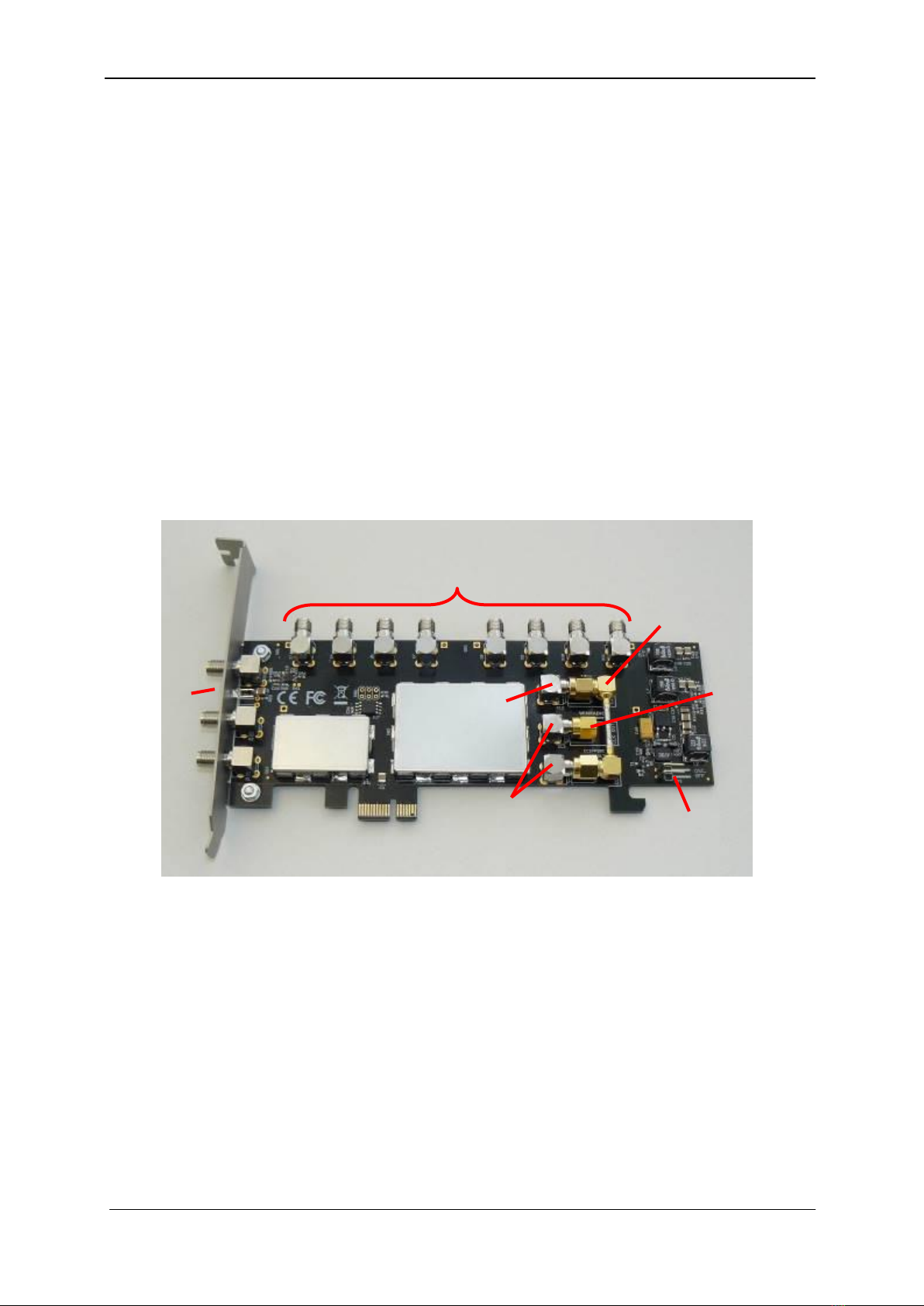
Moreover, in Extended Topology Configuration (ETC), each WR-G35DDCi receiver has to be
equipped with the WR-ETC-100 ‘WiNRADiO Extended topology Configuration kit’(ETC kit).
Therefore, for ETC configuration, the number of ETC kits needed is equal to number of
WR-G35DDCi receivers in the coherent multichannel group. The ETC kit is described in
Section 2.3. The purpose of the ETC kit is to allow for external distribution of the sampling
clock and digital synchronization signals, outside of the PC.
For coherent operation, all WR-G35DDCi receivers must be clocked at exactly the same
frequency and phase. To achieve this requirement, it is necessary to distribute a sampling
clock from a single low phase noise clock source (from the Clock Kit). Therefore, the
receivers have to be equipped with an ADC Clock Input Option (/CR) for external
sampling clock provision.
Similar to the sampling clock, all commands and operations of the receivers must be
synchronized accordingly to the coherent sampling clock. For this reason, the receivers have
an external interconnection for digital synchronization, which is also provided on receivers
with an ADC Clock Input Option (/CR).

WR-G35DDCi Multichannel Coherent Application Guide for Extended topology configuration (ETC)
5
An example of a one receiver, forming part of a multichannel coherent system in ETC
configuration is shown in Picture 1-2.
Picture 1-2: An example of a one WR-G35DDCi receiver, forming part of a multichannel
coherent system in ETC configuration with the ETC kit, installed into a PC (PC chassis and
other PC connections omitted for clarity). The WR-CC1PPS-100 kit is also required for
coherent operation, but is not shown in this picture.
The coaxial cables (shown in the picture) which are connected to the ETC kit carry the
sampling clock from the WR-CC1PPS-100 kit as well as the digital synchronization signals
needed to coherently synchronize all of the receivers together. The synchronization signals
are connected in a daisy chain manner; thus, two coaxial cables are needed to connect this
particular receiver to its two neighbouring receivers.

WR-G35DDCi Multichannel Coherent Application Guide for Extended topology configuration (ETC)
6
2. Parts description of the coherent system
2.1 WR-G35DDCi connectors
The connectors required for coherent operation of the WR-G35DDCi receivers are shown in
Pictures 2-1 and 2-2 (present when the /CR option has been fitted):
Picture 2-1: Rear panel connectors of the WR-G35DDCi
Picture 2-2: Digital synchronization connector of the WR-G35DDCi, viewed on the PCB side

WR-G35DDCi Multichannel Coherent Application Guide for Extended topology configuration (ETC)
7
2.2 The WiNRADiO Coherence Clock & 1PPS Kit (WR-CC1PPS-100)
The ‘WiNRADiO Coherence Clock & 1PPS Kit’(hereafter referred to as the 'Clock Kit')
provides production and distribution of a coherent 100 MHz clock for up to eight
WR-G35DDCi receivers as well as digital synchronization of the receivers. It also features an
internal frequency reference of 0.5 ppm stability, input for external frequency reference and
digital input for a 1PPS pulse or external trigger pulse. The Clock Kit consists of the following
components (shown in Picture 2-3):
1. Coherent clock generator board with 1PPS input
2. SMA patch cables for Coherent clock distribution (9 pcs)
3. Digital synchronization cables for each WR-G35DDCi receiver (8 pcs) –unused in
ETC configuration
4. Digital synchronization cable for Coherent clock generator board –unused in ETC
configuration
5. Frequency reference SMA interconnect cable
6. SMA terminators (7 pcs + 1 piece pre-installed on the board, see 8 below)
7. Sampling clock SMA coaxial jumper (factory pre-installed on the board)
8. Sampling clock SMA terminator (factory pre-installed on the board)
9. Standard circuit board jumper
Picture 2-3: The WiNRADiO WR-G35DDCi Coherence Clock & 1PPS Kit (the Clock Kit)
6
2
5
1
3
4
7
9
8
9x
7x
8x

WR-G35DDCi Multichannel Coherent Application Guide for Extended topology configuration (ETC)
8
2.2.1 Coherent clock generator board
The Coherent clock generator board is shown in Picture 2-4. It is a PCIe card, which has to
be installed into PCIe slot inside a PC. The board generates a 100 MHz sampling clock for
up to eight WR-G35DDCi receivers. The sampling clock is locked to a frequency reference,
which can be internal or external. It also can distribute a 1PPS trigger signal from the 1PPS
input to the WR-G35DDCi receivers when used in a standard installation, but in the ETC
configuration this feature is not utilized.
In the ETC configuration, this board has to be accompanied with additional hardware –the
PCIe bracket multi-SMA adapter, described in Section 2.4. This hardware carries the clock
signals generated by this board out of the PC chassis, so the sampling clock can be
distributed to the receivers externally to the PC. As the sampling clock is distributed
externally, there is no requirement for this card to be installed together with any of
the WR-G35DDCi receivers in the ETC configuration.
No software driver is required for operation of the Coherent clock generator board.
For the technical specification of the board, please refer to chapter 5 of this document.
1 PCIe connector
2 SMA connectors for sampling clock
output
3 Frequency reference output REF OUT
4 Frequency reference input REF IN
5 Locked indicator
6 1PPS trigger input –unused in ETC
configuration
7 SMA connectors for local oscillator
output
8 SMA connector for local oscillator
input
9 Pin header for disabling the oscillator
10 Factory pre-installed SMA jumper
11 Factory pre-installed SMA terminator
Picture 2-4: Front view of the Coherent clock generator board with 1 PPS input
1
2
6
5
4
3
7
8
11
10
9

WR-G35DDCi Multichannel Coherent Application Guide for Extended topology configuration (ETC)
9
2.2.2 PCIe connector
The PCIe connector provides power to the Coherent clock generator board. As there is no
data communication running through the PCIe connector, no software driver is required for
proper operation of the board. However, the board must be installed into a PCIe slot inside of
a PC.
2.2.3 SMA connectors for sampling clock output
There are eight SMA connectors for the sampling clock output provided on the Coherent
clock generator board. These are located on the top of the board and are facing upwards.
Each WR-G35DDCi receiver within a coherent group must be connected to one of these
ports using the SMA patch cables (for Coherent clock distribution) supplied with the Clock Kit
and described in Section 2.2.9. All ports are equivalent; therefore, any receiver within a
coherent group can be connected to any of these ports. However, unused ports have to be
terminated using the 50 ohm SMA terminators for proper operation.
Because the sampling clock is distributed externally to the PC in the ETC configuration,
extra hardware is needed to carry the clock signals out of the PC chassis. The PCIe bracket
multi-SMA adapter described in chapter 2.4.
For the technical specification of the sampling clock output signal, please refer to Chapter 5.
2.2.4 Digital synchronization interface
The digital synchronization interface is located on the rear side of the board. It is unused in
the ETC configuration and has to be left unconnected when operating in the ETC
configuration.
Picture 2-5: Rear view of the Coherent clock generator board showing the location
of the digital synchronization interface marked in red –it is unused and has to be left
unconnected in the ETC configuration

WR-G35DDCi Multichannel Coherent Application Guide for Extended topology configuration (ETC)
10
2.2.5 Frequency reference output REF OUT
The frequency reference output is an SMA connector providing the 10 MHz (internally
derived) frequency reference output signal. This output can be connected to the REF IN input
port (Section 2.2.6) if the internal frequency reference operation of the board is required. Use
the Frequency Reference SMA Interconnect cable (described in Section 2.2.12 and provided
with the Clock Kit) to connect the REF OUT port to the REF IN port.
If unused, this port must be properly terminated using the 50 ohm terminator.
For the technical specification of the REF OUT, please refer to Chapter 5.
2.2.6 Frequency reference input REF IN
A signal provided to the frequency reference input REF IN serves as a frequency reference
for the 100 MHz sampling clock generator. It is a 50 ohm terminated SMA connector.
A 10 MHz reference signal must be provided on this input.
This input can be connected to the REF OUT output port (Section 2.2.5) if the internal
frequency reference operation of the board is required. Use the Frequency Reference SMA
Interconnect cable (described in Section 2.2.12 and provided with the Clock Kit) to connect
the REF OUT port to the REF IN port.
For the technical specification of the REF IN input, please refer to Chapter 5.
2.2.7 1PPS trigger input
The 1PPS trigger input is unused in the ETC configuration and has to be left unconnected
when operating in the ETC configuration.
2.2.8 Locked indicator
The ‘Locked’indicator is lit whenever the 100 MHz sampling clock generator is locked to
the frequency reference signal provided at the REF IN port. For more information about the
REF IN port please refer to Section 2.2.6.

WR-G35DDCi Multichannel Coherent Application Guide for Extended topology configuration (ETC)
11
2.2.9 SMA patch cables for Coherent clock distribution
There are nine SMA patch cables (45 cm long) supplied with the Clock Kit. Eight of these
cables are used in the ETC configuration to carry the sampling clock from the Coherent clock
generator board to eight SMA adapters located on the PCI bracket SMA adapter; described
in Section 2.4. The cable carries the clock signal out of the PC chassis to distribute it to all
WR-G35DDCi receivers which are in coherent operation.
For interconnection, only use the original WiNRADiO SMA patch cables supplied with the
Clock Kit as these are specially matched to be coherent.
Picture 2-6: WiNRADiO coherent SMA patch cable
2.2.10 Digital synchronization cables for each WR-G35DDCi receiver
There are eight digital synchronization cables supplied with the Clock Kit. These are unused
in the ETC configuration, therefore do not install them. However, these cables should be kept
safely, in case the Clock Kit is required to operate in standard (non-ETC) coherent receiver
operation in the future.
Picture 2-7: Digital synchronization cable for the WR-G35DDCi receiver,
unused in the ETC configuration (see text)

WR-G35DDCi Multichannel Coherent Application Guide for Extended topology configuration (ETC)
12
2.2.11 Digital synchronization cable for the Coherent clock
generator board
Similar to the digital synchronization cables described in the previous Section, this cable is
unused in the ETC configuration, therefore do not install this cable. However, this cable
should be kept safely, in case the Clock Kit is required to operate in standard (non-ETC)
coherent receiver operation in the future.
Picture 2-8: Digital synchronization cable for the Coherent clock generator board,
unused in the ETC configuration (see text)
2.2.12 Frequency reference SMA interconnect cable
The frequency reference SMA interconnect cable is used to interconnect the internal
reference output REF OUT of the Coherent clock generator board to the frequency reference
input REF IN of the same board, after it is installed into a PC. If an external frequency
reference is used, this cable is not needed and should be kept safely, in case the internal
reference operation is required in the future.
For installation of the cable please refer to chapter 3 of this document.
Picture 2-9: SMA interconnect cable for the frequency reference

WR-G35DDCi Multichannel Coherent Application Guide for Extended topology configuration (ETC)
13
2.2.13 SMA terminators
The Clock Kit comes with eight 50 ohm SMA terminators. These terminators must occupy all
unused sampling clock outputs on the Coherent clock generator board. If all sampling clock
outputs on the Coherent clock generator board are connected to the ‘PCIe bracket
multi-SMA adapter’(as described in Section 2.4) and some of the outputs on the PCI bracket
SMA adapter are unused, all these unused outputs must have terminators installed on them.
A minimum of two WR-G35DDCi receivers can be connected as a coherent pair, so six
terminators are needed to terminate the sampling clock outputs. A seventh terminator is
provided in case the external reference is used with the Coherent clock generator board.
In such a case, the terminator must be installed on the REF OUT port of the Coherent clock
generator board.
Picture 2-10: SMA terminators
The eighth terminator comes factory pre-installed on the Coherent clock generator board,
terminating the secondary sampling clock oscillator output as shown in picture 2-11.
Picture 2-11: SMA terminator (marked in red) are factory pre-installed on the
secondary sampling clock oscillator output

WR-G35DDCi Multichannel Coherent Application Guide for Extended topology configuration (ETC)
14
2.2.14 Sampling clock oscillator input and outputs
The Coherent clock generator board has two sampling clock oscillator outputs and one input
for the sampling clock oscillator. These are factory connected as shown in Picture 2-12 using
an SMA jumper cable as described in Section 2.2.15, and one SMA 50 ohm terminator.
These factory connections need not to be altered for normal operation when using the
Coherent clock generator board to drive up to eight coherent receivers.
The purpose of these connectors is to enable the use of two Coherent clock generator
boards to coherently drive up to sixteen receivers. For details on how to use two Coherent
clock generator boards (to drive up to sixteen receivers) please refer to chapter 4 of this
document.
The factory connections consists of one 50 ohm terminator installed on one of the sampling
clock outputs and an SMA jumper cable as described in Section 2.2.15. This interconnects
the sampling clock, from the sampling clock oscillator output to the input of the sampling
clock oscillator.
Picture 2-12: Factory pre-installed SMA jumper cable interconnecting (marked in red) the
primary sampling clock oscillator output with the sampling clock oscillator input. Please note
the mandatory terminator installed on the secondary sampling clock oscillator output.
2.2.15 SMA jumper cable
The Clock Kit comes with an SMA jumper cable to connect the primary sampling clock
oscillator output to the sampling clock oscillator output. This SMA jumper is factory
pre-installed and is shown in picture 2-12. The jumper must be replaced with a proper patch
cable when using two Coherent clock generator boards, to distribute the sampling clock to up
to sixteen receivers. For details on how to use two Coherent clock generator boards (to drive
up to sixteen receivers) please refer to chapter 4 of this document.

WR-G35DDCi Multichannel Coherent Application Guide for Extended topology configuration (ETC)
15
2.2.16 Pin header for disabling the sampling clock oscillator
The 'pin header' for disabling the sampling oscillator is shown in picture 2-13 with its
corresponding jumper is shown in picture 2-14. No jumper is installed on the header for
normal operation of a single Coherent clock generator board.
The purpose of the pin header and its corresponding jumper is to provide the ability to turn
off the local sampling clock oscillator on one of the Coherent clock generator boards when
two Coherent clock generator boards are used to coherently drive up to sixteen receivers.
For details on how to use two Coherent clock generator boards (to drive up to sixteen
receivers) please refer to chapter 4 of this document.
Picture 2-13: Pin header for disabling the sampling clock oscillator (marked in red)
Picture 2-14: Jumper for disabling the sampling clock oscillator

WR-G35DDCi Multichannel Coherent Application Guide for Extended topology configuration (ETC)
16
2.3 The WiNRADiO ETC kit (WR-ETC-100)
The ‘WiNRADiO ETC kit’ (hereafter referred to as the 'ETC Kit') provides coherent
synchronization capability between multiple WR-G35DDCi receivers operating in ETC mode.
A single ETC kit is needed for each WR-G35DDCi receiver. In other words, the number of
required ETC kits is equal to the number of coherent receivers.
The ETC kit converts coherent synchronization signals from the Digital synchronization
connector of the WR-G35DDCi (described in Section 2.1 and shown in the Picture 2-2) into
signals carried over standard 50 ohm coaxial SMA cables. This enables the receivers to be
installed while distributed in different PCs. The ETC Kit consists of the following components
(shown in Picture 2-15):
1. The Extended topology configuration board (ETC board)
2. Digital synchronization cable for the ETC board
3. The 30 cm SMA sampling clock patch cable
4. The CLOCK SMA coaxial cable for external connections of the sampling clock
5. The SYNC SMA coaxial cable for external connections of synchronization
Picture 2-15: The WiNRADiO ETC kit (WR-ETC-100) and its components
2
1
3
4,5

WR-G35DDCi Multichannel Coherent Application Guide for Extended topology configuration (ETC)
17
2.3.1 ETC kit board
The ETC board is shown in Picture 2-16. This is a PCIe card, which has to be installed into a
PC, next to and connected to each WR-G35DDCi receiver; one ETC board is required for
each receiver. The board receives synchronization signal from the previous receiver in the
synchronization chain through the SYNC IN connector and re-sends it to the next receiver in
the chain through the SYNC OUT connector. The SYNC IN connector on the first-in-chain
board can be left unconnected, or it can be used to supply the 1PPS signal when
time-stamping functionality is required. The SYNC OUT connector on the last-in-chain board
has to be left unconnected.
No software driver is required for operation of the ETC board.
For the technical specification of the board, please refer to chapter 5 of this document.
1 PCIe connector
2 SMA connector SYNC IN for the synchronization signal input
3 SMA connector SYNC OUT for the synchronization signal output
4 Digital synchronization interface for connection to the WR-G35DDCi receiver
5 SMA adapter for the sampling clock
Picture 2-16: The ETC kit board
1
2
3
5
4

WR-G35DDCi Multichannel Coherent Application Guide for Extended topology configuration (ETC)
18
2.3.2 PCIe connector
The PCIe connector provides power to the ETC board. As there is no data communication
running through the PCIe connector, no software driver is required for proper operation of
the board. However, the board must be installed into a PCIe slot inside of a PC.
2.3.3 SMA connector SYNC IN
The purpose of the SYNC IN connector is to receive the synchronization signal from the
preceding ETC card in the synchronization chain. Therefore, the SYNC IN connector has to
be connected to the SYNC OUT connector of the preceding ETC board in the synchronization
chain. To facilitate this connection, the SMA synchronization coaxial cable (the SYNC cable)
described in Section 2.3.9 is used.
The SYNC IN connector on the first-in-chain board can be left unconnected. Alternatively, it
can be used as the input for the 1PPS signal, when timestamping functionality is required.
The synchronization protocol utilized on this interface is proprietary to WiNRADiO, therefore
no further specification is provided.
2.3.4 SMA connector SYNC OUT
The purpose of the SYNC OUT connector is to transmit the synchronization signal to the
receiver next in the synchronization chain. Therefore, the SYNC OUT connector has to be
connected to SYNC IN connector of the ETC board which follows it in the synchronization
chain. To facilitate this connection, the SMA synchronization coaxial cable (the SYNC cable)
described in Section 2.3.9 is used.
The SYNC OUT connector on the last-in-chain board has to be left unconnected.
The synchronization protocol utilized on this interface is proprietary to WiNRADiO, therefore
no further specification is provided.
2.3.5 Digital synchronization interface
The digital synchronization interface of the ETC board transfers synchronization signals
between the ETC board and the receiver. The digital synchronization cable for the ETC board
(described in Section 2.3.7) attaches to this connector and provides a connection to the
digital synchronization connector of the receiver (described in Section 2.1 and shown in the
Picture 2-2).
The synchronization protocol utilized on this interface is proprietary to WiNRADiO, therefore
no further specification is provided.

WR-G35DDCi Multichannel Coherent Application Guide for Extended topology configuration (ETC)
19
2.3.6 SMA adapter for the sampling clock
The SMA adapter for the sampling clock allows for entrance of the sampling clock to the PC
chassis interior. In ETC configuration, all connections between receivers and the Coherent
clock generator board (see Section 2.2.1) are done externally to the chassis of the PCs.
However, the Coherent clock input of the receiver shown in Picture 2-1 is located on the
receiver, which is installed inside the PC chassis. This SMA adapter passes the sampling clock
from the PC chassis - exterior to interior. Externally to the PC chassis, this SMA adapter is
connected to the Coherent clock generator board’s clock output. Internally, the 30 cm SMA
patch cable supplied with the ETC kit (Section 2.3) is used to carry the sampling clock from
the SMA adapter to the Coherent clock input of the receiver (shown in Picture 2-1).
2.3.7 Digital synchronization cable for ETC board
The digital synchronization flat cable for the ETC board provides connection between the
digital synchronization connector of the ETC board (described in Section 2.3.1) and the
digital synchronization connector of the receiver (described in Section 2.1 and shown in the
Picture 2-2).
The cable is fully reversible, i.e. there is no requirement to install a specific end of the cable
to the specific board. Therefore, the orientation of the cable is arbitrary when installing the
cable.
Picture 2-17: The Digital synchronization flat cable for the ETC board front view
(top) and back view (bottom)
2.3.8 30 cm SMA sampling clock patch cable
The 30 cm SMA sampling clock patch cable is shown in Picture 2-18. It connects between
the SMA adapter for the sampling clock described in Section 2.3.6 and the sampling clock
input of the receiver shown in Picture 2-1. Its purpose is to carry the sampling clock from
the exterior of the PC to the receiver.

WR-G35DDCi Multichannel Coherent Application Guide for Extended topology configuration (ETC)
20
For interconnection, only use the original WiNRADiO 30 cm SMA sampling clock
patch cable supplied with the ETC Kit, as it is specially matched to be coherent.
Picture 2-18: The 30 cm SMA sampling clock patch cable
2.3.9 SMA coaxial cables for external connection of the sampling
clock and synchronization
There are two long SMA coaxial cables supplied with the ETC Kit (shown in the Picture 2-19).
Both cables are almost identical, but differ in purpose and connection. The cables are
distinguished by a labelled sticker attached to them.
First cable is called the CLOCK CABLE (see Picture 2-19 and 2-20 on the left) and is used to
distribute the sampling clock from the Coherent clock generator board of the Clock Kit to all
WR-G35DDCi receivers which are in the coherent group.
The other cable is called the SYNC CABLE (see Picture 2-19 and 2-20 on the right) and is
used to link the receivers in a daisy chain like manner, to synchronize the receivers for
coherent operation. Each SYNC CABLE has the delay value specified on its sticker. The delay
value is marked as “DELAY n CLK” where ‘n’ is an integer number, which specifies the
amount of sampling clock cycles by which the cable delays the signal.
These cables can be manufactured in various lengths; however, the length is not arbitrary.
As mentioned above, the length of the cable is marked on the sticker of the SYNC CABLE in
by the number of sampling clock cycles which it delays the signal. Shortest cable has a delay
of 2 sampling clock cycles and is approx. 0.8 metres long. The longer cable has a delay of 3
sampling clock cycles and is approx. 2.8 metres long. If longer cables are needed, please
contact WiNRADiO.
All cables used for coherent operation of receivers must be the same length and type in the
ETC configuration. Cables of various length and/or types cannot be mixed within one
coherent group of receivers. Also, the user must specify the delay of the SYNC CABLE in the
software, so the software can compensate for the delay.
Table of contents
Other Winradio Receiver manuals