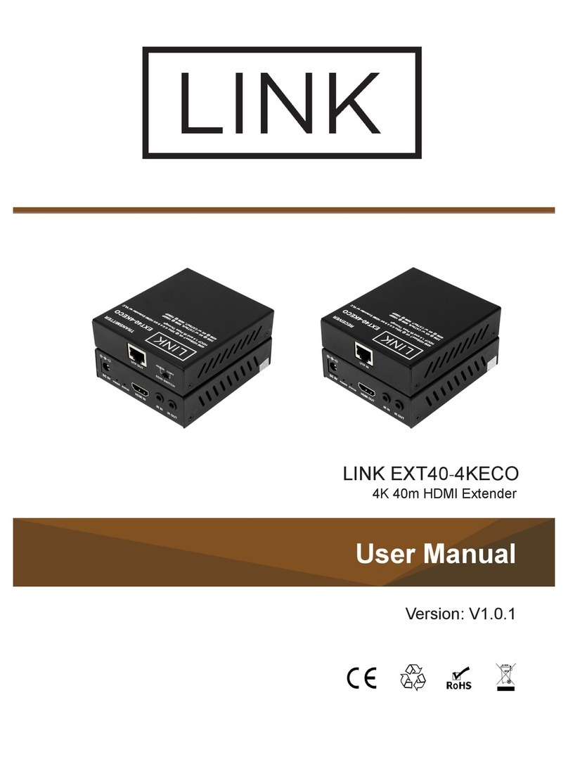
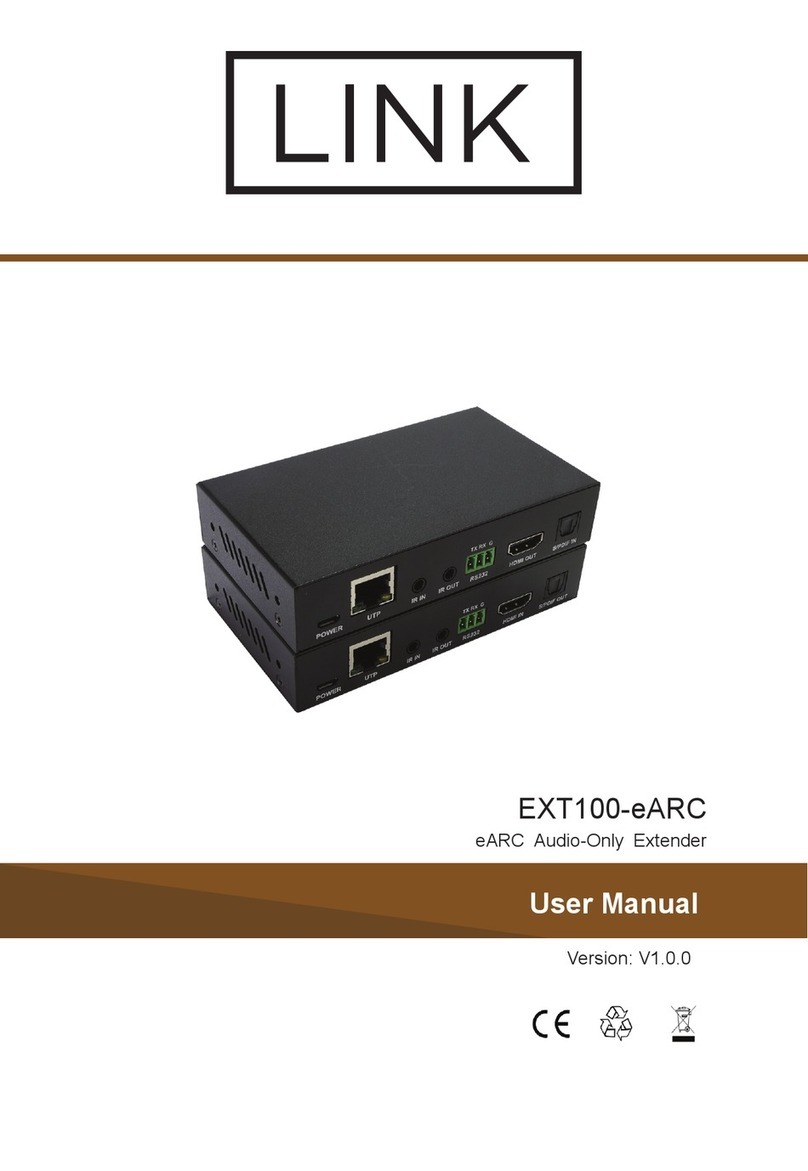
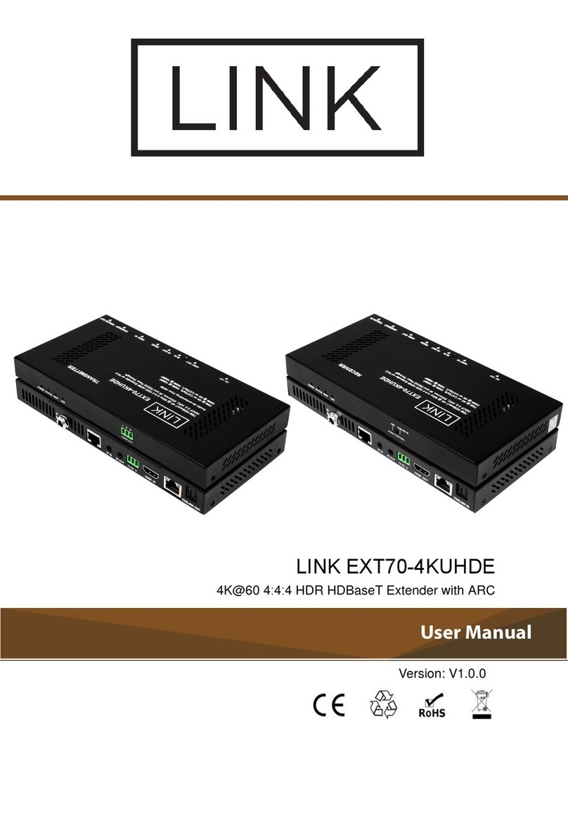
Link EXT40-4K User manual

User Manual
Version: V1.0.0
LINK EXT40-4K
40M HDBaseT 4K @ 60Hz 4:2:0 HDMI Extender


1. Do not expose this apparatus to
rain, moisture, dripping or
splashing and that no objects filled
with liquids, such as vases, shall be
placed on the apparatus.
6. Clean this apparatus
only with dry cloth.
2. Do not install or place this unit in
a bookcase, built-in cabinet or in
another confined space. Ensure the
unit is well ventilated.
3. To prevent risk of electric
shock or fire hazard due to
overheating, do not obstruct the
unit’s ventilation openings with
newspapers, tablecloths,
curtains, and similar items.
4. Do not install near any heat
sources such as radiators, heat
registers, stoves, or other apparatus
(including amplifiers) that produce
heat.
5. Do not place sources of naked
flames, such as lighted candles, on
the unit.
7. Unplug this apparatus
during lightning storms or
when unused for long
periods of time.
8. Protect the power cord
from being walked on or
pinched particularly at
plugs.
9. Only use attachments /
accessories specified by
the manufacturer.
10. Refer all servicing to
qualified service
personnel.
Important Safety Instructions

This equipment has been tested and found to comply with the limits for a
Class B digital device, pursuant to Part 15 of the FCC Rules. These limits are
designed to provide reasonable protection against harmful interference in a
residential installation. This equipment generates uses and can radiate radio
frequency energy and, if not installed and used in accordance with the
instructions, may cause harmful interference to radio communications.
However, there is no guarantee that interference will not occur in a particular
installation. If this equipment does cause harmful interference to radio or
television reception, which can be determined by turning the equipment off
and on, the user is encouraged to try to correct the interference by one or
more of the following measures:
-- Reorient or relocate the receiving antenna.
-- Increase the separation between the equipment and receiver.
-- Connect the equipment into an outlet on a circuit different from that to
which the receiver is connected.
-- Consult the dealer or an experienced radio/TV technician for help.
Changes or modifications not expressly approved by the party responsible for
compliance could void the user's authority to operate the equipment.
Warnings of FCC

1
Table of Contents
Introduction .................................................................................................... 2
Features ................................................................................................... 2
Package Contents .................................................................................... 2
Specifications............................................................................................ 3
Panel Description ..................................................................................... 4
Application Diagram....................................................................................... 6
RS232 Operation ........................................................................................... 7
Troubleshooting ............................................................................................. 8
Warranty Terms and Conditions ..................................................................... 9

2
Introduction
Thank you for purchasing this product. For proper installation and optimum
performance, please read the instructions in this manual carefully.
LINK EXT40-4K is a slim transmitter receiver pair, which can extend HDMI
1080P@60Hz signals up to 70m/230ft and 4K@60Hz (chroma sub-sampling
4:2:0 8-bit only) signals up to 40m/130ft via a single Cat 6a/7 cable. It features
bi-directional PoC. It also supports bi-directional IR and RS232 pass-through.
Features
•Supports resolutions up to 4K@60Hz 4:2:0 8bit and HDCP 2.2.
•Over a Cat 6a/7 cable, extends 4K@60Hz 4:2:0 8bit up to 40m/130ft and
1080P up to 70m/230ft.
•Over a Cat 5e/6 cable, extends 4K@60Hz 4:2:0 8bit up to 35m/115ft and
1080P up to 60m/200ft.
•Bi-directional PoC, one power adapter at either transmitter or receiver
side can power both units.
•Supports bi-directional IR and RS232 pass-through.
Package Contents
•1 x EXT40-4K Extender Set
•1 x Power Adapter (DC 18V 1A)
•1 x IR Emitter
•1 x Broadband IR Receiver (30-50 KHz)
•1 x IR-AC IR Coupler Cable
•2 x 3.5mm 3-Pin Phoenix Connector
•4 x Mounting Brackets (with Screws)
•1 x User Manual

3
Specifications
Technical
Input/Output Signal Type HDMI with 4K@60Hz 4:2:0, HDCP 2.2
Input/Output Resolution
Supported
Up to 4096x2160@60Hz, including
4K@60Hz/4K@30Hz/1080P/1080i/720P
Note: 4096x2160/3840x2160@50/60Hz is
based on chroma sub-sampling 4:2:0 8-bit only.
Deep color 4K: 8/10/12 bit
1080P: up to 16 bit
Maximum Data Rate 10.2 Gbps
Maximum Pixel Clock 340MHz
Audio Format Supported
Supports multichannel audio up to PCM 7.1,
Dolby True HD, DTS HD Master Audio, Dolby
Atmos and DTS:X
General
Operating Temperature 0°C to 45°C (32°F to 113°F)
Storage Temperature -20°C to 70°C (-4°F to 158°F)
Humidity 10% to 90%, non-condensing
ESD Protection
Human-body Model:
±8kV (Air-gap discharge)/
±4kV (Contact discharge)
Power Supply DC 18V 1A
Power Consumption
(Maximum) 8.88W (Pair, PoC)
Device Dimension
(W x H x D)
108.8mm x 15mm x 64.2mm/
4.3" x 0.6’’ x 2.5’’ each for TX/RX
Product Weight 0.18kg/0.4lb each for TX/RX

4
Transmission Distance:
Note: T568B straight-through Category cable is recommended.
Cable Type Range Supported Video
HDMI Input/Output:15m/50ft 1080P@60Hz
Input/Output: 10m/33ft 4K@60Hz 4:2:0
Cat 5e/6 60m/200ft 1080P@60Hz
35m/115ft 4K@60Hz 4:2:0
Cat 6a/7 70m/230ft 1080P@60Hz
40m/130ft 4K@60Hz 4:2:0
Panel Description
Front Panel
4321
No. Name Description
1 Power LED On/Off: The device is powered on/off.
2 Status LED On: The device is working properly.
Off: The device is not working properly.
3 HDCP LED On: HDCP protected content is being transmitted.
Blinking: Non-HDCP protected content is being
transmitted.
Off: No content is being transmitted.
4 Link LED On:HDBT link is normal.
Blinking/Off: No HDBT link or link error.

5
Rear Panel
Transmitter
f
edcba
Receiver
6
5
4
3
1 2
No. Name Description
a & 1 DC 18V Connect to the power adapter.
b HDBT OUT Connect to the receiver via a Cat 5e/6/7 cable.
c & 3 IR IN Connect to the IR receiver provided.
d & 4 IR OUT Connect to the IR emitter provided.
e & 5 RS232 For RS232 pass-through.
f HDMI IN Connect to an HDMI source device.
2 HDBT IN Connect to the transmitter via a Cat 5e/6/7
cable.
6 HDMI OUT Connect to an HDMI display device.

6
Application Diagram
HDBT
Blu-ray Player
TV
Blu-ray Player
remote
IR Emitter 2
IR Receiver 2
HDMI IN
HDMI OUT
TV remote
IR Receiver 1
IR Emitter 1
Receiver
Transmitter
Note: Connect the broadband IR receiver to IR IN and the IR emitter to IR
O U T.

7
RS232 Operation
RS232 ports can be used for bi-directional RS232 signal pass-through
between the transmitter and receiver.
HDBT
Receiver
Transmitter
RS232 cable
RS232 Device
RS232 cable
RS232 Device
RX
TX
GND
TX
RX
G
RS232 Port Connected RS232 Device Pins

8
Troubleshooting
1. No Power
Ensure the power is on.
Ensure you use the power adapter provided in the package.
2. No Picture or Video Flash
Ensure all devices are on, and all cables are qualified and
connected properly. Ensure all the cables’ length are within the
maximum distance (refer to Specification table).
Ensure all the LED indicators are normal.
When connecting source to display directly, ensure them can work
properly.
Ensure the input resolution is supported by the device.
Ensure the input resolution is within 4K@30Hz when Dolby vision
signal is input.
3. Weak or Not Working IR Signal
Ensure the devices support IR control (not Bluetooth/WIFI).
Ensure you use the IR cables provided in the package, and install
them correctly according to the Application Diagram.
Pay attention to the control angle and distance.
IR Cable IR Emitter IR Receiver
Suggested Angle 0° 0°
Distance (Max) 30cm 8m
When work with the third-party device, ensure it follows the pin
definition below.
IR Receiver
Gnd
IR signal
5V
IR Emitter
5V
IR signal

9
Warranty Terms and Conditions
For the following cases LINK shall charge for the service(s) claimed for the
products if the product is still remediable and the warranty card becomes
unenforceable or inapplicable.
1. The original serial number (specified by LINK) labeled on the product
has been removed, erased, replaced, defaced or is illegible.
2. The warranty has expired.
3. The defects are caused by the fact that the product is repaired,
dismantled or altered by anyone that is not from a LINK authorized
service partner. The defects are caused by the fact that the product is
used or handled improperly, roughly or not as instructed in the
applicable User Guide.
4. The defects are caused by any force majeure including but not limited to
accidents, fire, earthquake, lightning, tsunami and war.
5. The service, configuration and gifts promised by salesman only but not
covered by normal contract.
6. LINK preserves the right for interpretation of these cases above and to
make changes to them at any time without notice.


This manual suits for next models
1
Table of contents
Other Link Extender manuals