Link HD System Manual
Document # -HD System Man Iss 1.1 Issue 1.1 06/11/2007
Page 8 of 31
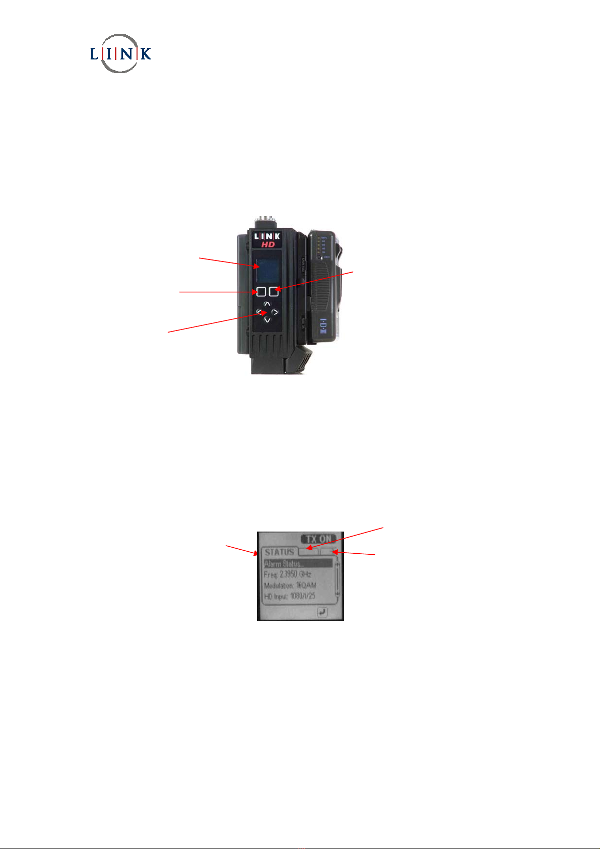
2.1.2 Operators Menus
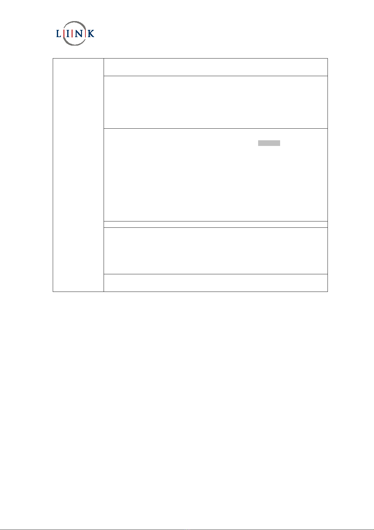
The Greyed Out parameters not selectable with the current version of code.
The table below is spilt into the three ‘Tabs’ corresponding to STATUS, SETUP and ADVANCED.
Status Sub Menu Options Function
Alarm Status Video Lock Display whether encoder is locked to the video input
Audio A Lock Display whether encoder is locked to the audio input
Audio B Lock Display status
Frequency 2.345GHz Display & Set current Frequency
Modulation QPSK, 16, 64QAM Display & Select mode
HD Input 1080i/25 Display current video standard
Setup Options Function
Output Off, Carrier Low ,
Carrier Only, On
RF output selection
Profiles Last Used Display last
Store Store in 1:6
Load Load from 1:6
Restore Defaults Factory Defaults
LCD Setup LCD Contrast Setable 1:9 Set to 9 - maximum
LCD Backlight Setable 1:7 Set to 7 - maximum
LCD Timeout On , Off
Camera Control Freq Set required UHF frequency
Only if L1420 is Cam Type Set required camera type
fitted Status CC OK Confirms Camera Controller status
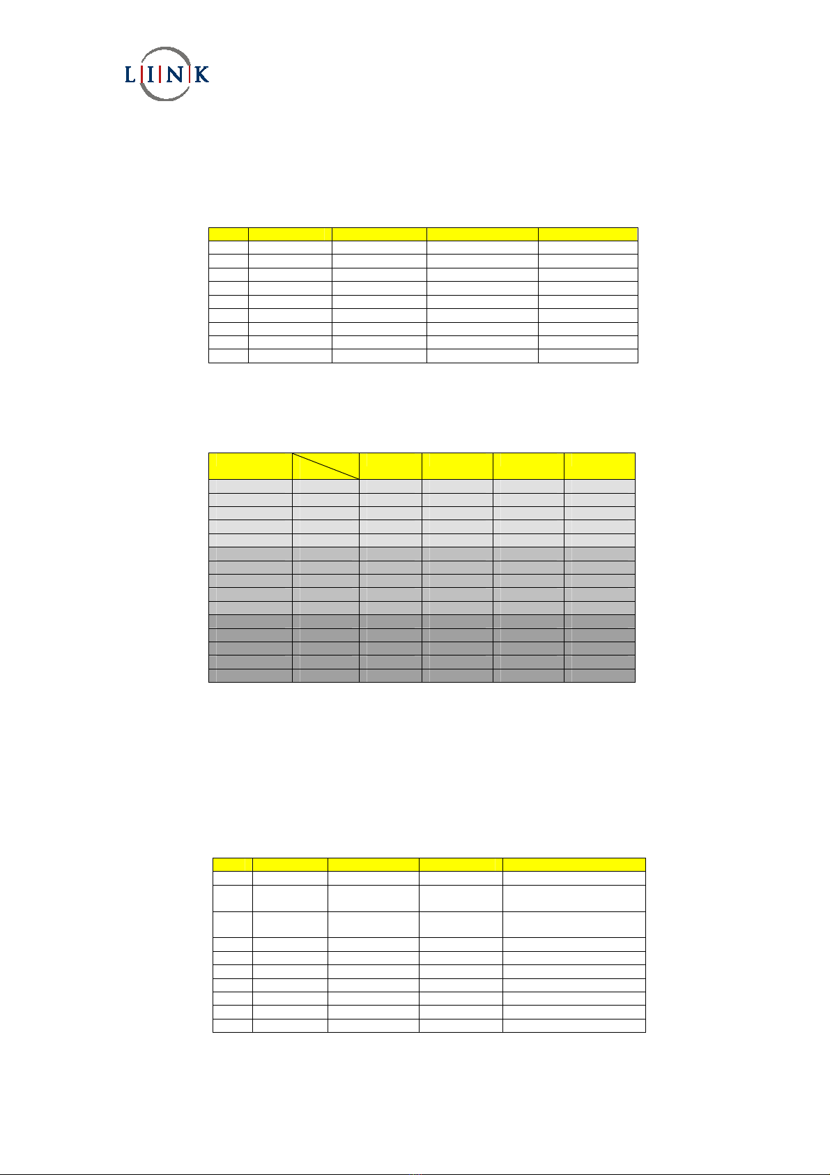
Advanced Options Function
Video HD Input Select HD format
Test Patten On, Off
Video Loss Bars On, Off, Video+Audio
Auto Line Std On, Off
Audio DID 0:9999
Noise Reduction On, Off
Frame Rate Display current
Video Lock Displays status
DVBT/LMST Output Off, Carrier Low , Carrier Only, On
Guard Interval 1/4, 1/8, 1/16, 1/32
Modulation QPSK, 16, 64QAM
FEC Rate 1/2, 2/3, 3/4, 5/6, 7/8
Polarity Normal , Invert
Width 6, 7, 8, 10, 20 MHz
Power 10, 50, 100mW
Freq Set current Frequency
Delivery Desc. On, Off
DVBS Output Off, Carrier Low , Carrier Only, On
Sym 1.234MSym/s
Modulation QPSK, 16, 64QAM
FEC Rate 1/2, 2/3, 3/4, 5/6, 7/8
Polarity Normal , Invert
Power 10, 50, 100mW
Frequency Set current Frequency
Roll Off 25 , 35%
Delivery Desc. On, Off
Unit Unit Mode ASI, LMS-T, DVB-T, Reserved
422 DTS Offset 0 – 999 offset
420 DTS Offset 0 – 999 offset
Soft Version Version Number
UpConv Type
FPGA Version
Ser. Num Unit Serial Number