Link L1360 User manual

LINK RESEARCH PRODUCT MANUAL
L1360 XPc Transmitter Manual
Contact: Link Research Main +44 (0) 1923 474 060
Support +44 (0) 1923 474 099
Web: www.linkres.co.uk
Images are for illustration only and may differ from components supplied
Link Research Ltd www.linkres.co.uk Support UK/Europe + (44) 1923 474099 USA +(1)9786715700
Page 1 of 14 CL140067 Issue B Link XPc Manual
Link XPc
Compact Encoder/Modulator Manual
1 Introduction 3
2 Product Description 3
3 Product Operation 4
3.1 Serial port interface 4
3.2 LEDs 4
3.3 Basic operation 4
3.4 Default Settings 5
3.5 Specification 6
3.6 Connector Interface 7
3.7 Mechanical 8
4 Configuration & Firmware Upgrades 9
4.1 XPc Configuration via Link Control 9
4.2 Firmware Upgrades 10
5 XPc Product Part Numbers 13
6 Part Numbers for XPc Accessories 13

Images are for illustration only and may differ from components supplied
Link Research Ltd www.linkres.co.uk Support UK/Europe + (44) 1923 474099 USA +(1)9786715700
Page 2 of 14 CL140067 Issue B Link XPc Manual
Document Link XPc Encoder/Modulator Manual
Issue Date Comments
A June 2009 Working draft
B June 2009 Typo’s & minor changes
Safety and Compliance
Any mains power equipment must be earthed. Operate the equipment within environmental limits and
ensure as much ventilation as possible (Normally Temp 0C-50C <99% humidity). Only authorised
personnel should open the product and any repair or warranty will be invalidated if the unit is
opened.
The equipment has been designed to be CE compliant and an EC Declaration of Conformity and
Technical files are available on request.
Please contact Link SUPPORT any issues.
Please ensure that normal anti-static precautions are taken when removing the XPc interface
connector from the main unit.
Operators are advised to always check that their application complies with the requirements of the
relevant frequency authority. Frequency allocations vary from time to time. Most require individual
licences for operation. All known restrictions are indicated in the notes below. Contact details for EU
authorities can be found at http://ec.europa.eu/enterprise/rtte/spectr.htm.
This product is not approved for permanent mounting in commercial vehicles.

Images are for illustration only and may differ from components supplied
Link Research Ltd www.linkres.co.uk Support UK/Europe + (44) 1923 474099 USA +(1)9786715700
Page 3 of 14 CL140067 Issue B Link XPc Manual
1Introduction
The Link XPC compact Encoder/Modulator is a highly integrated product, which can be employed in a
number of different scenarios. It includes an SD MPEG2 encoder and also supports a range of
modulators ; DVB-T and LMS-T. LMS-T is Link Research’s proprietary modulation scheme, which
offers higher bitrate and robustness in many applications.
This manual describes operation of the XPC only. For details of the receiving end please see the
relevant manual.
This manual assumes a reasonable knowledge of broadcast systems. It is intended to be used as a
basic reference; full support with integration of the product will be provided directly by Link Research
Ltd.
2Product Description
The XPC is intended to be mounted using the four mounting holes (for mechanical details see section
3.7.1).
The cooling fan allows the unit to operate in ambient temperatures of at least 50˚C. Ensure that there
is sufficient clearance around the unit to allow free airflow into and from the cooling slots. Operation in
higher temperature environments may be possible depending on what external cooling is available –
consult Link Research Ltd. if this is required. It should not be mounted on a hot surface.
The XPc provides two RF outputs (with phantom power) designed to drive a range of amplifiers and
active antennas. Please contact Link Research Ltd. for the full range of options.
Interface
connector
Cooling slots Status LEDs
Control Buttons

Images are for illustration only and may differ from components supplied
Link Research Ltd www.linkres.co.uk Support UK/Europe + (44) 1923 474099 USA +(1)9786715700
Page 4 of 14 CL140067 Issue B Link XPc Manual
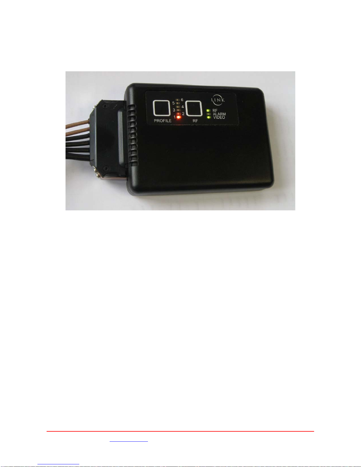
3Product Operation
The XPC has a simple control panel that allows the selection of pre defined Profiles and the control of
the RF output. LEDs provide an indication of the unit’s status; the current Profile and state of the RF
output and unit Alarms. The Profiles are edited in the XPc using Link Control software running on a PC.
See section 4.1 for details.
3.1 Serial port interface
The XPC has an RS232 port which can be used to communicate with a PC or similar. The protocol for
this communication is described in a separate document, which is available on request from Link
Research Ltd. Link Control
3.2 LEDs
Profile:
Colour Function
Off No power present
Orange 1-6 Indicates the current
selected Profile
RF :
Colour Function
Off RF Off
Green RF outputs On
Alarm:
Colour Function
Off Operational
Red Alarm condition
Video :
Colour Function
Off Video not locked
Green Video locked
3.3 Basic operation
As an example of how to get started with the XPc
1. Connect the required RF power amp(s) to the RF output of the harness.
2. Connect the required video and audio (if required) inputs using the appropriate multipin
harness.
3. Apply power to the XPc. Confirm that one of the Profile LED turns orange, this indicates the
last used Profile.
4. Select the required operating Profile using the Profile button.
5. Turn on the RF outputs using the RF button.

Images are for illustration only and may differ from components supplied
Link Research Ltd www.linkres.co.uk Support UK/Europe + (44) 1923 474099 USA +(1)9786715700
Page 5 of 14 CL140067 Issue B Link XPc Manual
3.4 Default Settings
Following a ‘Link Control Memory/Restore Defaults it will be necessary to select the required operating
mode and modulation configuration.
The default settings are :-
Memory Memory Profile 0
Auto Set Service Name 1
Modulation Frequency 2.295MHz
RF Output Off
Mod. Mode QPSK
Mod. Type LMS-T
Guard Interval 1/16
FEC 2/3
Bandwidth 10MHz
Mod. Polarity Normal
Scrambling Scrambling Off
EBS Key 00000000
BISS Key 0000000000000
Video Source Input PAL - CVBS
Bars On Video Loss Bars + Ident
Audio DID 767
Video Encoder Encoder On
Auto Bit Rate On
Enc Bit Rate 9.2122Mb/s
MPEG 4:2:2
GOP Length 12
Video PID 0512
Audio A Standard MPEG L2
Input Analogue
Mic/Line Line level
Level Left 162
Level Right 162
Bit Rate 224Kbs
Mode Stereo
Language Eng
Tone Level -18dBFS
PID 4112
RS232 Data Data Off
Baud Rate 9600
Data PID 0100
Unit Mode LMS-T
Address 1
420 DTS Offset 90
422 DTS Offset 90
Quant VBI 5
Default Set WBU

Images are for illustration only and may differ from components supplied
Link Research Ltd www.linkres.co.uk Support UK/Europe + (44) 1923 474099 USA +(1)9786715700
Page 6 of 14 CL140067 Issue B Link XPc Manual
3.5 Specification
3.5.1 Video Formats
The XPC will also accept video inputs as either composite (CVBS) or SDI in the following formats :-
Standard
Input
Connector
Bars 625
Internally
Generated
Bars 525
Internally
Generated
SDI 625 SDI
SDI 525 SDI
PAL CV
NTSC CV
NTSC No Ped CV
PAL-M CV
PAL-N CV
3.5.2 Modulation Modes supported
3.5.2.1 DVB-T
The Table below shows the modulation modes supported for DVB-T operation, together
with the corresponding bit rates. It should be noted that this corresponds to the total data rate
which includes the video, audio and any user data.
Modulation GI
CR
1/4 1/8 1/16 1/32
QPSK 1/2 4.97 5.52 5.85 6.03
QPSK 2/3 6.63 7.37 7.80 8.04
QPSK 3/4 7.46 8.29 8.78 9.04
QPSK 5/6 8.29 9.21 9.75 10.05
QPSK 7/8 8.70 9.67 10.24 10.55
16QAM 1/2 9.95 11.05 11.70 12.06
16QAM 2/3 13.27 14.74 15.61 16.08
16QAM 3/4 14.92 16.58 17.56 18.09
16QAM 5/6 16.58 18.43 19.51 20.10
16QAM 7/8 17.41 19.35 20.49 21.11
64QAM 1/2 14.92 16.58 17.56 18.09
64QAM 2/3 19.90 22.11 23.41 24.12
64QAM 3/4 22.39 24.88 26.34 27.14
64QAM 5/6 24.88 27.64 29.27 30.16
64QAM 7/8 26.12 29.02 30.73 31.66
3.5.2.2 LMS-T
The Table below shows the modulation modes supported for LMS-T operation, together
with the corresponding bit rates.
Modulation
GI
CR
1/8
10MHz 20MHz
1/16
10MHz 20MHz
QPSK 2/3 9.2 18.4 9.7 19.5
16QAM 2/3 18.4 36.8 19.5 39
64QAM 2/3 27.6 45.2 29.2 58.5
Note 64 QAM & 20MHz not available on current software, but will be available as a future
upgrade.
It should be noted that this corresponds to the total data rate which includes the video, audio
and any user data.
Images are for illustration only and may differ from components supplied
Link Research Ltd www.linkres.co.uk Support UK/Europe + (44) 1923 474099 USA +(1)9786715700
Page 7 of 14 CL140067 Issue B Link XPc Manual
Due to the improvement that LMS-T has over DVB-T these settings give approximately 50%
improvement of bit rates for the same level of ruggedness of the RF link.
For example DVB-T 16QAM, 1/32 GI, 1/2 CR gives 12Mbits whereas LMS-T 16QAM gives
18Mbits.
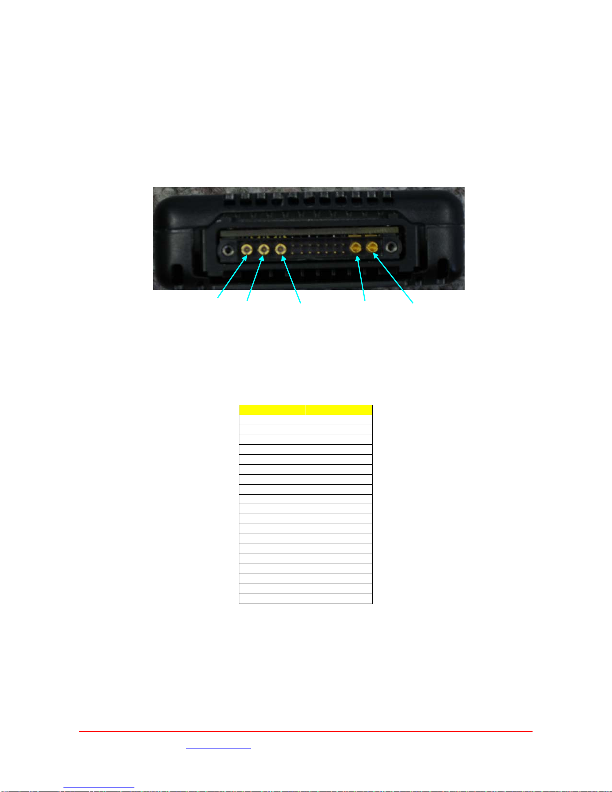
3.6 Connector Interface
This multipin connector carries all input and outputs to the XPc.
PCB Connector Harwin M80-5L11442M7-03-313-02-333
Mating Connector Harwin M80-4C11442F3-03-307-02-327
Signal Pin
Tx Data 1
Rx Data 2
0V 3
Tx Spare 4
Rx Spare 5
0V 6
SMBClk 7
SMBData 8
0V 9
Audio L+ 10
Audio L- 11
0V 12
Audio R+ 13
Audio R- 14
RF1 Output 15
RF2 Output 16
Video Input 17
Power In 18
0V 19
3.6.1 Video Input
Coax insert for input of either SD-SDI (SMPTE 259M) video or composite (CVBS) analogue video.
3.6.2 Audio
Stereo pair, differential inputs at Mic level or Line Level.
Switched 25dB gain for Mic input and an independant variable (+45 to -80dB) level control for both
Mic & Line. Adjustable via Link Control in 0.5dB steps.
>20kΩinput impedance
Pin19
0V
Pin18
Power In
Pin15
RF1
Pin16
RF2
Pin17
Video In

Images are for illustration only and may differ from components supplied
Link Research Ltd www.linkres.co.uk Support UK/Europe + (44) 1923 474099 USA +(1)9786715700
Page 8 of 14 CL140067 Issue B Link XPc Manual
Frequency response 50Hz to 15kHz <0.1dB
Frequency response 20Hz to 20kHz <0.5dB
+18dB clipping level (+18db ≡0dBFS)
3.6.3 RS232 Data & Control Port
The RS232 input / output of both the User Data and also Remote Control of the transmitter unit.
3.6.4 DC Power
12V DC nominal (10V minimum, 18V maximum) .
Max power ~ 6W excluding PA / PA’s. Also dependant upon RF output power and video standard
3.6.5 RF 1 & 2
Two outputs (-3dBm into 50Ωnominal) with phantom power to drive Link Research power
amplifier or active antenna.
Please contact Link Research Ltd. For details of available amplifiers and active antenna.
3.7 Mechanical
3.7.1 Dimensions:
3.7.2 Weight
190gms excluding mounting plate.
Images are for illustration only and may differ from components supplied
Link Research Ltd www.linkres.co.uk Support UK/Europe + (44) 1923 474099 USA +(1)9786715700
Page 9 of 14 CL140067 Issue B Link XPc Manual
4Configuration & Firmware Upgrades
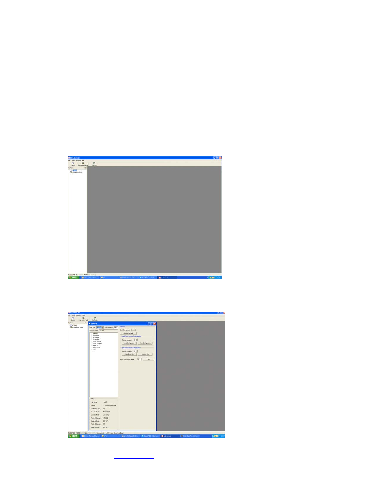
4.1 XPc Configuration via Link Control
Saving and restoring customised profiles is done by using the Link control programme. This is
available from the Link Research website :-
http://www.linkres.co.uk/link+research+firmware+updates
Connect the PC COM port to the XPc via a link L0002 serial interface cable ‘Remote’ connector.
Start the remote control programme by clicking on the Link Control icon and a window like that shown
below will open.
4.1.1 ‘Control’ Configuration of the XPc
Select the Control tab to enter the normal ‘Control’ configuration panel for the XPc.

Images are for illustration only and may differ from components supplied
Link Research Ltd www.linkres.co.uk Support UK/Europe + (44) 1923 474099 USA +(1)9786715700
Page 10 of 14 CL140067 Issue B Link XPc Manual
The ‘sub tabs’ can then be selected to enter the required page, the main operating parameters of the
XPc can then be selected.
These functions are divided into :-
1. Memory
2. Modulator
3. Multiplexer
4. Scrambling
5. Video Source
6. Video Encoder
7. Audio A
8. RS232 Data
9. Unit
It is important to note that any changes made are not automatically saved in a Profile memory and
will therefore be lost if the power is removed from the XPc.
The ‘Store Configuration’ in the ‘Memory’ page must be used to save a required configuration to one
of the six Profile memories.
The XPc can then be configured with one of these profiles from either the Load Configuration’ in the
‘Memory’ page or the front panel push button.
4.1.2 Diagnostic Configuration
It is also possible to configure the XPc via the Diagnostic Mode panel. This allows all functions of the
XPc to be controlled and monitored from a PC via Link Control.
It is not intended for normal functions to be controlled via this interface and care must be used when
controlling the XPc via these commands.
The commands are defined in the protocol document “Remote Control Protocol for Encoders” available
from the Link Research website :- http://www.linkres.co.uk/link+research+manuals
4.2 Firmware Upgrades
Link Research equipment is designed to allow for firmware upgrades providing new features and
continual improvements during the life of the product. Please consult the Link Research website for
details of the latest firmware releases. http://www.linkres.co.uk/support.php.
The XPc unit can be upgraded via the RS232 port. The required file can be downloaded from the Link
Research website and copied onto a local PC.
The terminal program TeraTerm is needed to be installed on a PC to allow loading of firmware updates
into the XPC.
The software. This can be obtained from the site
http://hp.vector.co.jp/authors/VA002416/teraterm.html
Images are for illustration only and may differ from components supplied
Link Research Ltd www.linkres.co.uk Support UK/Europe + (44) 1923 474099 USA +(1)9786715700
Page 11 of 14 CL140067 Issue B Link XPc Manual
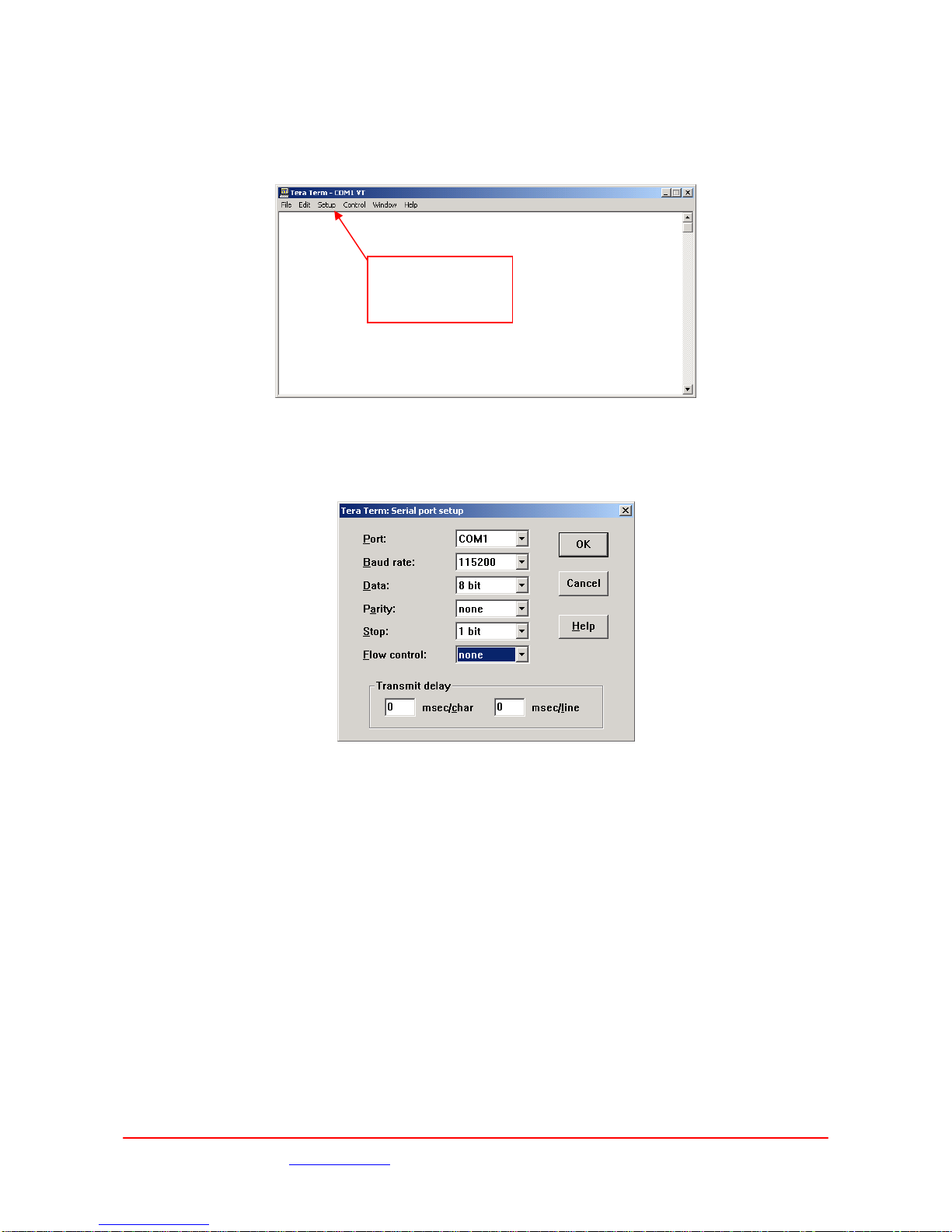
When TeraTerm is opened, it will show a window like that above. Choose the serial option and
configure it for a valid COM port. This will then open another window as shown below:
From the Set-up drop down menu, choose the serial port option to access the port configuration menu
(shown below).
Set the port up with the values shown in the screen dump and click ok.
The XPc must be connected to the PC with a serial cable (minimum connections 2 – 2, 3 –3 and 5 - 5)
between the chosen COM port and XPc data port. With the unit un-powered, hold down the Profile and
RF keys simultaneously on the front panel, apply the power and continue to hold the keys down for a
few seconds.
If the connection is successful, the following prompt will be seen on the PC screen.
Choose this drop down
menu and select serial
port baud rate 115200

Images are for illustration only and may differ from components supplied
Link Research Ltd www.linkres.co.uk Support UK/Europe + (44) 1923 474099 USA +(1)9786715700
Page 12 of 14 CL140067 Issue B Link XPc Manual
Select the dropdown menu File then Send File on the terminal, and select the download file, saved and
unzipped on the local hard drive.
Once complete, the progress window will disappear, and a short time later (3-5 minutes), the
message ‘Finished’ will appear on the terminal screen. The updated code is now ready to execute at
next power up.
N.B. If the power is interrupted at any stage during this process, the new code will not be
loaded.

Images are for illustration only and may differ from components supplied
Link Research Ltd www.linkres.co.uk Support UK/Europe + (44) 1923 474099 USA +(1)9786715700
Page 13 of 14 CL140067 Issue B Link XPc Manual
5XPc Product Part Numbers
Link Part
Number Product Description Details
L1360-2024 XPC Encoder Transmitter 2.05 – 2.45GHz
L1360-2427 XPC Encoder Transmitter 2.4 – 2.7GHz
6Part Numbers for XPc Accessories
Link Part
Number Description Details
L0060 XPc Cable harness
L0064 XPc Cable Harness
L3250-1927 200mW Amplifier Module
L3260-1927 100mW Amplifier Module
L3452-1927 100mW Active Car Amp/Antenna
L9990 Sony Z1 mounting kit
L9991 Sony PD170 mounting kit
L9992 Sony Z5/Z7 mounting kit
L9993 Sony EX3 mounting kit
L9994-AB Anton Bauer battery mounting kit
L9994-IDX IDX battery mounting kit
End of Document
Table of contents
Other Link Transmitter manuals

Popular Transmitter manuals by other brands

Fuji Electric
Fuji Electric FCX-CII SERIES instruction manual

Magtech
Magtech LTM-300 Series Operation manual

Aeta Audio Systems
Aeta Audio Systems SCOOP 3 5ASystem user manual

TechnipFMC
TechnipFMC Proline 300 HART manual

Devanco Canada
Devanco Canada Marantec M3-2312 instructions

Abilia
Abilia Progress PC manual


Monacor
Monacor TXA-800ST instruction manual

Vega
Vega VEGABAR 87 Quick setup guide

Lectronics
Lectronics SMB/E01Series instruction manual

ARTEX
ARTEX B406-4 Description, operation, installation and maintenance manual

TX Techniques
TX Techniques TX FM1 Technical manual

Eldat
Eldat Easywave RTS43 quick start guide