LinkPower CS300 User manual
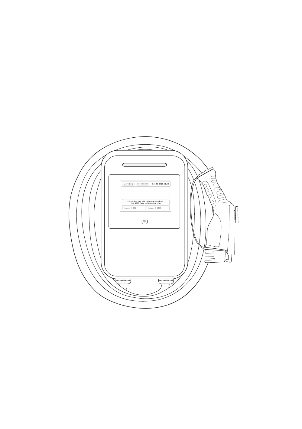
Electric Vehicle AC Charger
Installation Manual
For model: CS300


1. Safety Instructions.................................................................... 1
1.1. Warnings & Cautions............................................................................ 1
1.2. Installation Requirements.................................................................... 2
1.3. Daily Maintenance ............................................................................... 2
CONTENTS
1. Consignes De Sécurité Importantes ............................................ 4
1.1. Avertissement & Mise En Garde Généraux ........................................... 4
1.2. Exigence Avant L’installation ............................................................... 5
1.3. Daily Maintenance ............................................................................... 5
2. Product Introduction ................................................................. 7
2.1. Basic Interface .................................................................................... 7
2.2. Basic Dimension ................................................................................. 8
2.3. Specifications...................................................................................... 9
2.4. Design Standards............................................................................... 10
3. Accessories .............................................................................11
4. Tools for Mounting ...................................................................12
5. Plan for Mounting.....................................................................13
6. Operate Your Device .................................................................17
6.1. Operating Steps with Plug and Charge............................................... 17
6.2. Operating Steps with RFID Card ......................................................... 19
7. Light Codes .............................................................................21
7.1. After Start UP ..................................................................................... 21
7.2. Error and Warning Messages ............................................................. 21
8. FCC STATEMENT......................................................................22
9. Warranty and Maintenance .......................................................23

CS300
1
WARNING
1. Safety Instructions
WARNING
1.1. Warnings & Cautions
To avoid fire, injury or death, read and follow the instructions carefully during
installation, operation and maintenance.
DO NOT put fingers into the electric vehicle connector.
DO NOT use this product if the power cord or EV cable is frayed, insulation-
broken, or any other signs of damage.
DO NOT use this product if the enclosure or the EV connector is broken, cracked,
open, or shows any other indication of damage.
DO NOT remove cover or attempt to open the enclosure because of risk of
electric shock.
This device should be supervised when used around children.
This device must be grounded.
To avoid the risk of fire or electric shock, do not use this device with an
extension cord.
The suitability of the use of flexible cord in accordance with CE code, part I, rule
4-012, is to be determined by the local inspection authority.
To reduce the risk of fire, connect only to a circuit provided branch circuit over-
current protection in accordance with the CSA C22. 1– 15 Canadian Electrical
Code, Part 1 (Canada) or NOM-001-SEDE Electrical installations (utility) (Mexico)
or ANSI / NFPA 70 National Electrical Code (USA).
Circuit Breaker Options
Output Amperage (A) 16A 32A 40A 48A 80A
Circuit Breaker Options (A) 20A 40A 50A 60A 100A
CS300
2
WARNING
WARNING
CAUTION
CAUTION
Disconnect electrical power prior to installing the charging station.
Be sure to preview the user manual and ensure local building and electrical
codes are reviewed before installing the AC charger.
The AC charger should be installed by a qualified technician according to the
user manual and local safety regulations.
Avoid moisture or water in the charger. If there is water or moisture ingress
in the charger, it is necessary to immediately power off to avoid immediate
danger and notify the professionals to carry out maintenance before next use.
Please use the charger properly. Do not hit or press hard on the enclosure. If it
1.3. Daily Maintenance
1.2. Installation Requirements
Use appropriate protection when connecting to the main power distribution
cable.
Type B, C or D breaker with the rating current for table should be installed in the
upstream AC distribution box.
Disconnect switch for each ungrounded conductor of AC input shall be
provided by others in accordance with the National Electric Code, ANSI/
NFPA70.
The device shall be mounted at the height between 600 mm and 1200 mm
from ground.
Please keep the charger in a clean area with low humidity. Not recommended
to be installed in coastal environments with high humidity or thick dust.

CS300
3
WARNING
is damaged, please contact a professional technician.
Avoid placing the charger near hot objects and at high temperature locations
and away from dangerous substances such as flammable gases and corrosive
materials.
To avoid any danger, please do not put any heavy objects on the charger.

CS300
4
AVERTISSEMENT
1. Consignes De Sécurité Importantes
1.1. Avertissement & Mise En Garde Généraux
AVERTISSEMENT
Pour éviter les risques d’incendie, de blessure ou de mort, il faut lire et suivre
soigneusement les instructions pendant l’installation, l’utilisation et l’entretien.
Ne mettez pas les doigts dans le connecteur du véhicule électrique.
N'utilisez pas ce produit si le cordon d'alimentation flexible ou le câble EV est
effiloché, isoléou présentant tout autre signe de dommage.
N'utilisez pas ce produit si le boîtier ou le connecteur EV est cassé, fissuré, ouvert ou
montre toute autre indication de dommage.
Ne retirez pasle couvercle et n'essayez pas d'ouvrir le boîtier en raison du risque de
choc électrique.
Cet appareil doit être surveillé lorsqu'il est utilisé à proximité d'enfants.
Cet appareil doit être mis à la terre.
Pour éviter tout risque d'incendie ou de choc électrique, n'utilisez pas cet
appareil avec une rallonge électrique.
L'adéquation de l'utilisation du cordon flexible conformément au code ce, partie i,
règle 4-012, doit être déterminée par l'autoritéd'inspection locale compétente.
Pour réduire les risques d'incendie, ne connecter qu'à un circuit protection
contre les surintensités des circuits de dérivation conformément à la norme
canadienne CSA C22. 1-15 Code électrique, partie 1 (Canada) ou NOM-
001-SEDE Installations électriques (Mexique) ou ANSI / NFPA 70 National
Electrical Code (États-Unis).
Tableau Des Options Du Disjoncteur
Courant De Sortie (A) 16A 32A 40A 48A 80A
Options De Disjoncteur (A) 20A 40A 50A 60A 100A
CS300
5
AVERTISSEMENT
1.2. Exigence Avant L’installation
AVERTISSEMENT
MISE EN GARDE
Assurez-vous de consulter le manuel d'utilisation et assurez-vous que les
codes locaux du bâtiment et de l'électricité sont passés en revue avant d'installer
le chargeur.
Débranchez l'alimentation électrique avant d'installer la station de charge.
Le chargeur CA doit être installé par un technicien qualifié conformément au
manuel d'utilisation et aux réglementations de sécurité locales.
Utilisez une protection appropriée lors de la connexion au câble de distribution
d'alimentation principal.
Un disjoncteur de B, C ou D avec le courant nominal indiqué dans le tableau doit
être installé dans le boîtier de distribution CA en amont.
L'interrupteur de déconnexion pour chaque conducteur non mis à la terre de l'entrée
CA doit être fourni par des tiers conformément au Code national de l'électricité,
ANSI/NFPA70.
Cet appareil doit être monté à une hauteur entre 600 mm (2 pieds) et 1200 mm (4
pieds) du sol.
Veuillez conserver le chargeur dans un endroit propre et peu humide. Il n’est
pas recommandé de l'installer dans des environnements côtiers à forte
humidité ou à forte poussière.
1.3. Daily Maintenance
MISE EN GARDE
Évitez l'humidité ou l'eau dans le chargeur. En cas d'infiltration d'eau ou d'humidité
dans le chargeur, il est nécessaire de l'éteindre immédiatement pour éviter tout

CS300
6
AVERTISSEMENT
danger immédiat et d'avertir le personnel professionnel d'effectuer l'entretien
avant la prochaine utilisation.
Veuillez utiliser le chargeur correctement. Ne frappez pas ou n'appuyez pas
trop fort sur le boîtier. Si le boîtier est endommagé, veuillez contacter un
technicien professionnel.
Évitez de placer le chargeur à proximité d'objets chauds et à des endroits à
haute température et loin de substances dangereuses telles que des gaz
inflammables et des matériaux corrosifs.
Pour éviter tout danger, veuillez ne pas mettre d'objets lourds sur le chargeur.

CS300
7
INTRODUCTION
2. Product Introduction
2.1. Basic Interface
CAUTION: Avoid placing the charger near hot objects or high
temperature locations and away from dangerous substances such
as flammable gases and corrosive materials.
Rear Notch
Input Power
Cable
Charging
cable
LED Light
Indication
LCD Screen
SAE J1772
AC Charging
Connector
CS300
8
INTRODUCTION
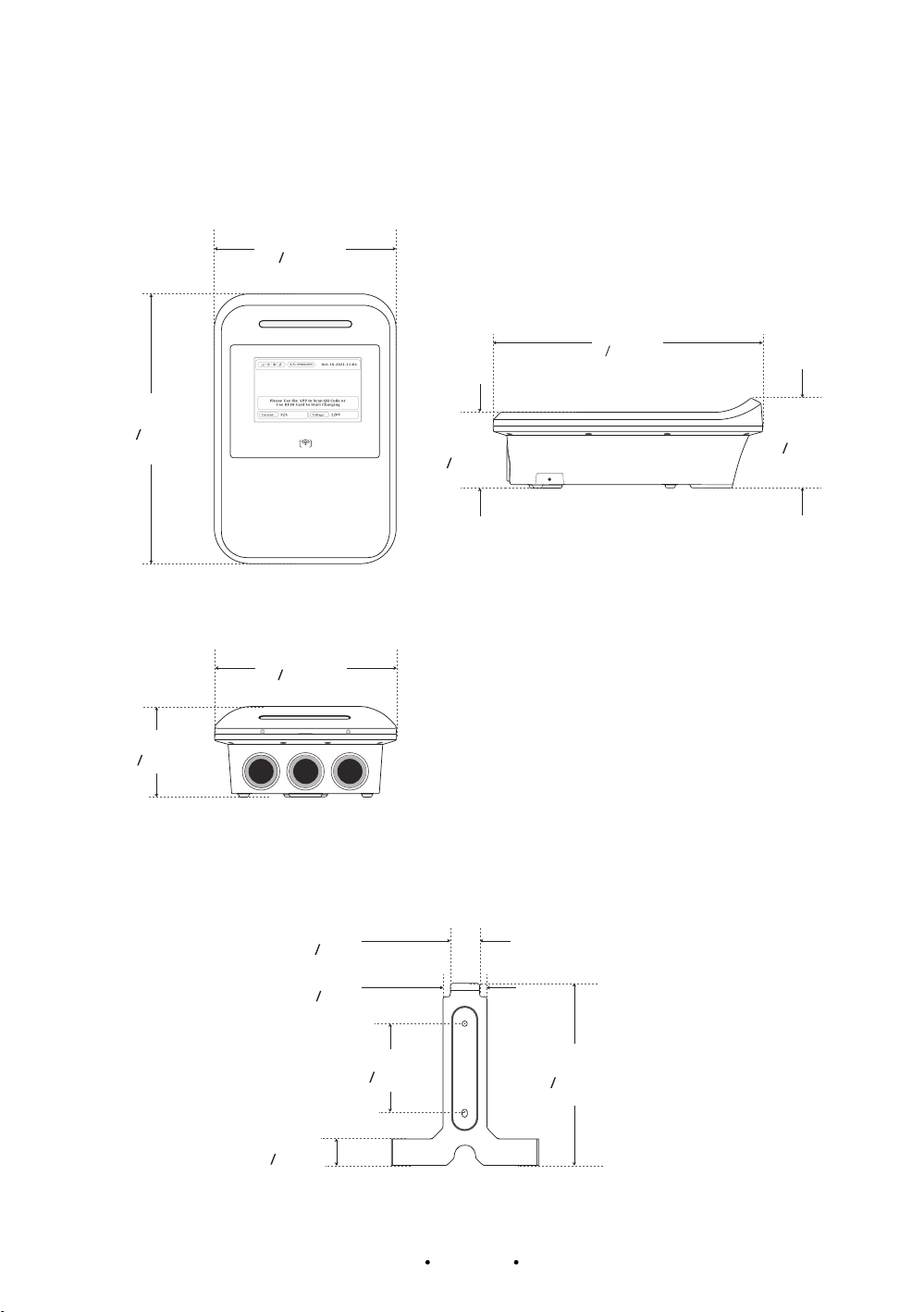
2.2. Basic Dimension
ENCLOSURE
WALL-MOUNTED HOLES
365 mm
14.37’’
365 mm
14.37’’
245 mm
9.65’’
245 mm
9.65’’
121.47 mm
4.78’’
87.4 mm
3.44’’
Front View Left View
Bottom View
102 mm
4.02’’
60 mm
2.36’’
120 mm
4.72’’
35 mm
1.38’’
40 mm
1.57’’
40 mm
1.57’’

CS300
9
INTRODUCTION
2.3. Specifications
Model Name CS300-32A CS300-40A CS300-48A CS300-80A
Power
Specification
Input AC Rating 208-240Vac
Max. AC Current 32A 40A 48A 80A
Frequency 60Hz
Max. Output Power 7.6kW 9.6kW 11.5kW 19.2kW
User Interface &
Control
Display 5”(7” optional) LCD Screen
LED Indicator Yes
Push Buttons Restart Button
User Authentication RFID(ISO/IEC 14443 A/B), APP
Communication
Network Interface LAN(Standard), Wi-Fi/Bluetooth/3G/4G Optional
Communication Protocol OCPP1.6 J/OCPP2.0.1 Upgradeable
Communication Function ISO/IEC 15118 Optional
Environment
Operating Temperature -22 ℉to 122 ℉
Humidity 5%~95% RH, Non-condensing
Altitude ≤6562ft(2000m), No Derating
IP/IK Level NEMA Type3R(IP65)/IK10
Mechanical
Cabinet Dimension(W×D×H) 9.65”×14.37”×4.78”(245mm×365mm×121.47mm)
Weight 16.98lbs(7.7kgs)
Cable Length 18ft(5.5m)(Standard)/25ft(7.5m)(Optional)
Protection Multiple Protection
OVP(Over Voltage Protection), OCP(Over Current
Protection), OTP(Over Temperature Protection),
UVP(Under Voltage Protection), SPD(Surge
Protection Detection), Grounding Protection,
SCP(Short Circuit Protection), Control Pilot Fault,
Relay Welding Detection, CCID Self-test
Regulation
Safety UL 2594, UL2231-1/-2
Certificate ETL, FCC
Charging Interface SAE J1772 Type 1

CS300
10
INTRODUCTION
UL 2594: Electric Vehicle Supply Equipment.
UL 2231-1: UL Prersonnel Protection System s for Electric Vehicle (EV) Supply
Circuits:General Requirements.
UL 2231: Personnel Protection Systems for Electric Vehicle (EV) Supply Circuits: Particular
Requirements for Protection Devices for Use in Charging Systems.
UL 2251: Plugs, Receptacles and Couplers for Electric Vehicles.
UL 62: Flexible Cords and Cables.
UL 991: Tests for Safety-Related Controls Employing Solid-State Devices.
UL 1998: Software in Programmable Components.
NFPA 70 Article 625: National Electrical Code, Electric Vehicle Charging System UL 840
(Clearance and Creepage).
2.4. Design Standards

CS300
11
ACCESSORIES
Electric Vehicle AC Charger
Installation Manual
For model: CS300
3. Accessories
Check the box to ensure you have this installation guide and these parts:
1AC Charger 2User Manual 3M4×8 Screws*2 4M3X8 Screws*2
5M6 Hexagonal
ExpansionScrews*2
6Standard RFID
Cards*2
7Mounting Bracket
No. Product Name Quantity Description
1AC Charger 1With attached input power cable and output charging cable.
2User Manual 1PDF version available online.
3M4×8 Screws 2For installing the AC Charger to the Bracket.
4M3X8 Screws 2For fastening front cover on AC Charger
5M6 Hexagonal
Expansion Screws 2For installing the Mounting Bracket to the wall / structure.
6Standard RFID Cards 2To start/stop charger for the unit with RFID reader.
7Mounting Bracket 1For easy drilling of 2 screws holes for AC Charger.
CS300
12
MOUNTING
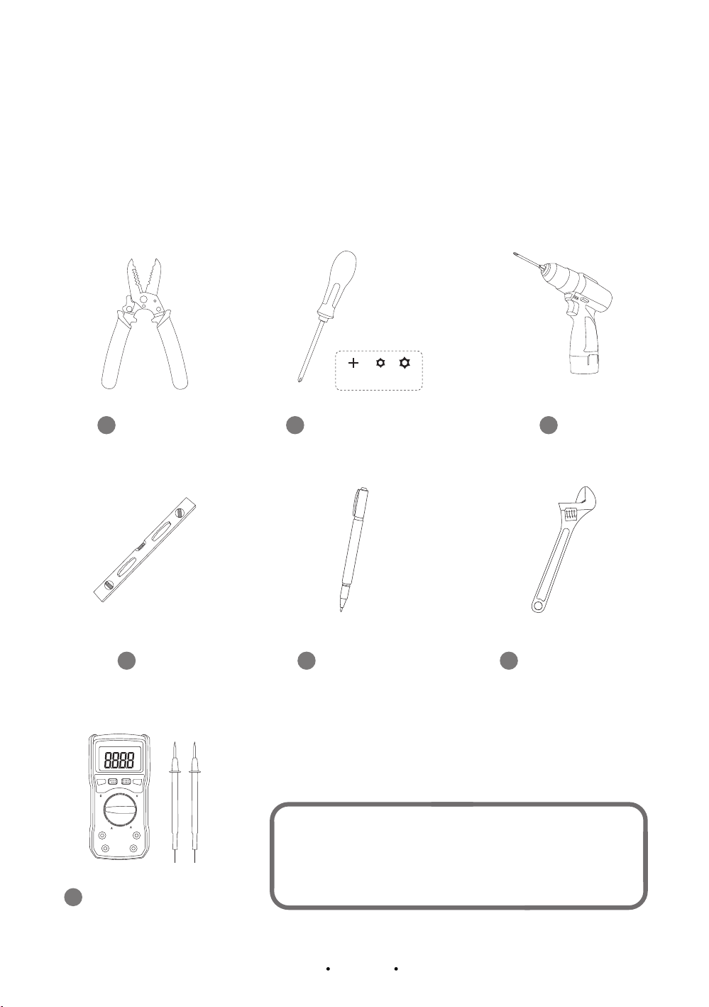
4. Tools for Mounting
Tools required before installing the Wall-mounted charger, gather the following tools:
T10 T20
1Wire stripper
7Voltmeter or digital multi-
meter (for measuring AC
voltage at the installation site)
5Pencil or marker
3Drill
6Adjustable wrench
4Level
2Phillips and T10, T20
screwdriver
NOTE: The above tools are very important, get
them ready prior to installation.
CS300
13
MOUNTING
5. Plan for Mounting
CAUTION: Not recommended to be installed in coastal
environments with high humidity or thick dust.
WARNING: In areas with frequent thunderstorms, add surge
protection at the service panel for all circuits. Ensure all power and
ground connections, especially those at the breaker and bus bar, are
clean and tight.
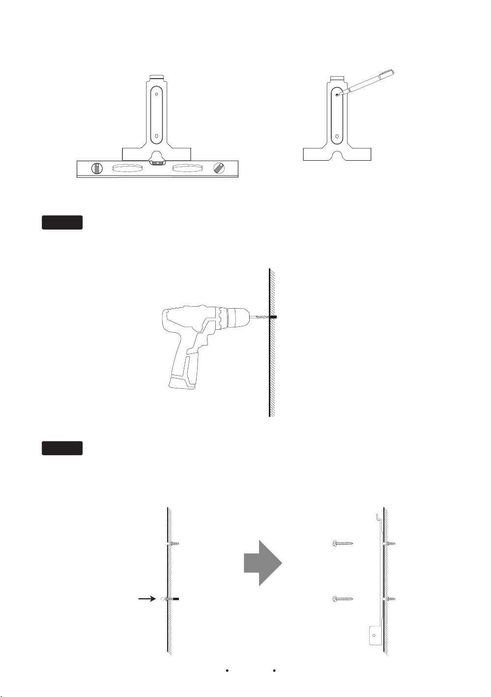
STEP 1
STEP 2
Select the appropriate mounting location with electrical capacity.
Use a level to verify if a bracket is horizontally aligned and mark the holes by one pencil.
i.Ensure the owner has chosen a mounting location that allows the charging cable to reach the
car’s charging port while still providing slack.
II. The device must be anchored on a solid wall or a stud with the dimensions: 2” x 4”.
III. The device shall be mounted at height between 2 feet (600mm) and 4 feet (1200mm).
CS300
14
MOUNTING
STEP 3
Drill 2 Screw Holes with a diameter of 0.33” and a depth of 2.05” by using #7 mounting
bracket.
Insert the
expansion nut
STEP 4
Nail #5 two expansion rubber sleeves into the holes and nail #5 two M6 hexagonal
expansion screws to secure the wall-mounted bracket on the wall. Then level the
brackets.

CS300
15
MOUNTING
T20
STEP 5
STEP 6
Align the rear notch of charger with the wall-mounted
bracket and fit the screw holes of the right and left
side with #3 M4×8 Screws.
For the safety purpose, please set circuit breaker protection in the input part of EV
Charger. Please follow the instructions below:
Wire the Circuit
WARNING
CAUTION
This device must be grounded. Disconnect electrical power prior to installing
the charging station.
Improper connection of the equipment-grounding conductor would result in
a risk of electric shock. Check with a qualified electrician or service man if
you are not sure whether the product is properly grounded. Do not modify the
plug provided with the product – if it doesn’t fit the outlet, have a proper outlet
installed by a qualified electrician.
Use appropriate protection when connecting to the main power distribution
cable.
Circuit Breaker Options
Output Amperage (A) 16A 32A 40A 48A 80A
Circuit Breaker Options (A) 20A 40A 50A 60A 100A

CS300
16
MOUNTING
D27
CP CP
J27
PE
PE
L1
L1
L2
L2 PEL1L2
PE L1 L2
T10
STEP 7
STEP 8
Please unclick the shelf with slotted screwdriver, connect L1 with grid L1, L2 with grid
L2 and lead the PE to the grid PE. Click back the shelf, and fix the front cover back and
tighten with #8 M3X8 Screws 2 screws at the buttom.
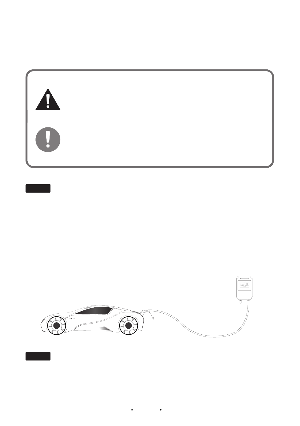
Overall outlook after installation
This manual suits for next models
4
Table of contents


