VESTEL EVC04-AC Series User manual

Page 1 of 64
EVC04 AC22-AC7.4
SERVICE MANUAL

Page 2 of 64
Revision History:
First Version
Uğur Korcan İçten
Second Version
Overcurrent and under voltage values
Third Version
Smart Model extension
Fourth Version
Fifth Version
Sixth Version
Seven Version
Eight Version

Page 3 of 64
Table of Contents
1SYSTEM SPECIFICATION.............................................................................................................. 5
General Specification ................................................................................................................. 5
Technical Specification............................................................................................................... 6
System Block Diagram ............................................................................................................... 7
2BOARD LAYOUT .......................................................................................................................... 8
Main Board............................................................................................................................... 8
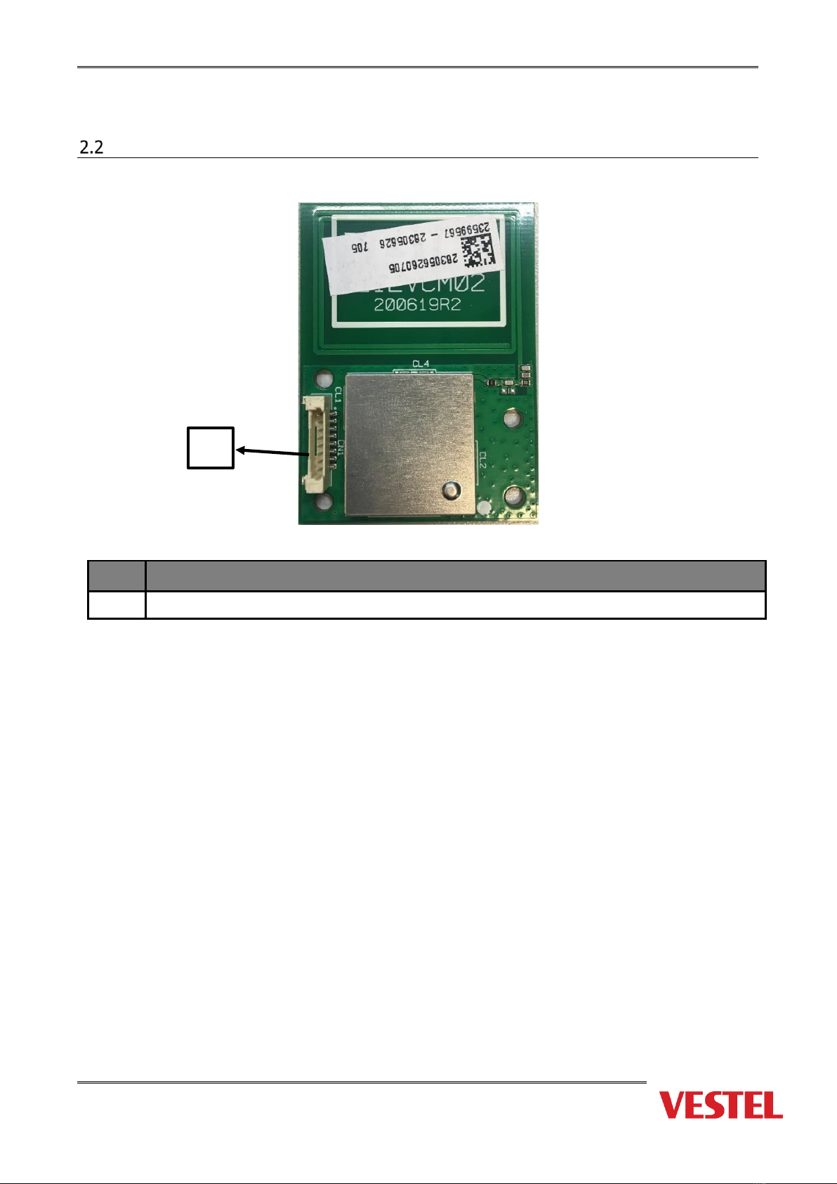
RFID Module............................................................................................................................. 9
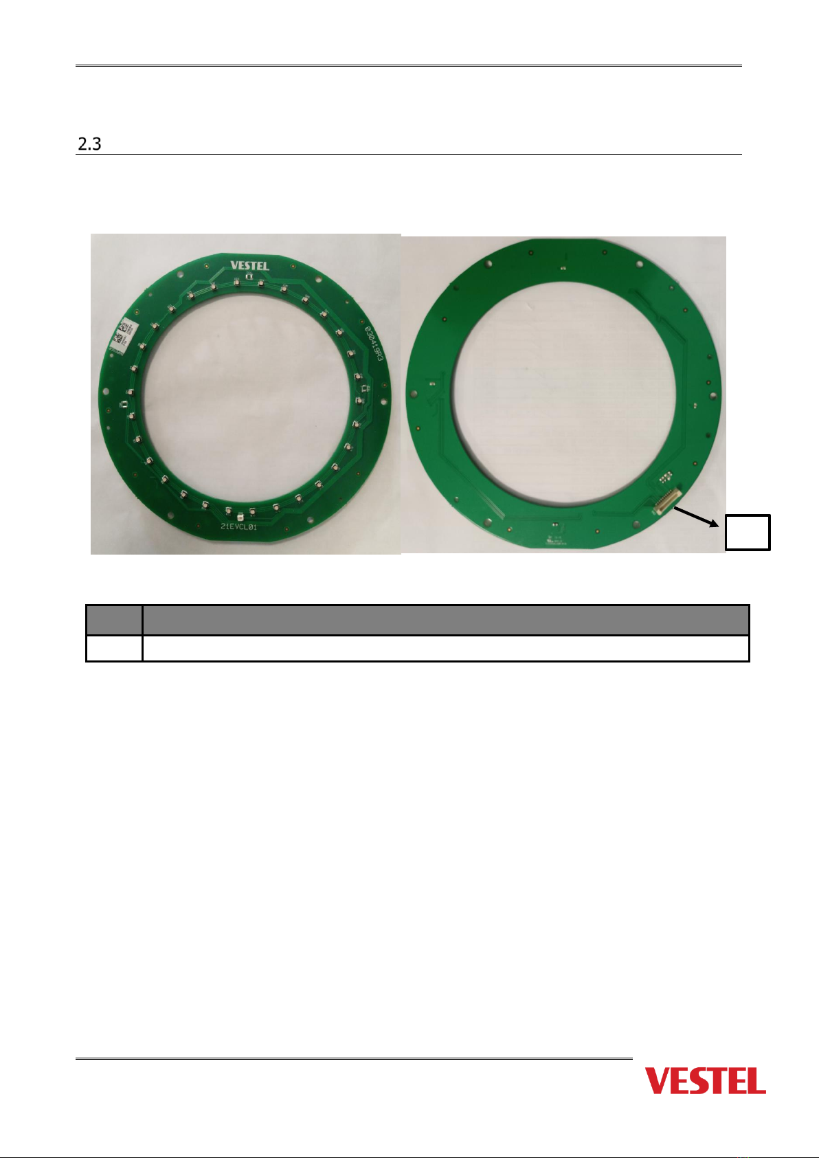
LED Board...............................................................................................................................10
HMI Board (Smart Model) .........................................................................................................11
LTE Board (Smart Model)..........................................................................................................12
Wi-Fi Board (Smart Model) ........................................................................................................13
3PRODUCT BEHAVIOR..................................................................................................................14
LED Behavior...........................................................................................................................14
4DISASSEMBLING OF EVC04 .........................................................................................................16
Required Tools for Installation ...................................................................................................16
Changing Main Board................................................................................................................17
General Information and Warnings ...........................................................................................17
Changing HMI Board (Smart Model)
...........................................................................................25
Changing Display (Smart Model) ................................................................................................27
Changing RFID Board
...............................................................................................................28
Changing LED Board
.................................................................................................................30
Changing WiFi Board
................................................................................................................32
Changing LTE Board
.................................................................................................................33
Changing Interlock
...................................................................................................................34
Changing Output Socket..........................................................................................................35
Changing Electric Terminals.....................................................................................................36
Changing Cosmetic Frame .......................................................................................................38
5RCCB AND DC6mA......................................................................................................................39
6CABLE GLAND NUT.....................................................................................................................43
7SOFTWARE UPDATE GUIDE WITH VESLINK ..................................................................................44
Software Update Procedure .....................................................................................................44
8 GETTING LOG WITH EVC TESTER AND MOBILE APPLICATION............................................................50
9 DETAILS OF VESTEL EVC TESTER....................................................................................................60
10 TROUBLESHOOTING.....................................................................................................................62

Page 4 of 64
Notes, Cautions, and Warnings
Signs used in this manual
Some words and phrases are written in a different format to get your attention.
Note: It is being used to put emphasis on useful information and critical points regarding
the product.
WARNING:
CAUTION: Disconnect product from the power supply before attempting any operation
on it.

Page 5 of 64
1SYSTEM SPECIFICATION
General Specification
Model Name
MODEL DESCRIPTION: EVC04-AC**-*
EVC04 : Electric Vehicle AC Charger (Mechanical Cabinet 04)
1st Asterisk (*) : Rated Power
7 : 7.4 kW (1PhaseSupplyEquipment)
11 : 11 kW (3Phase Supply
Equipment) 22 : 22 kW (3Phase
Supply Equipment)
2nd Asterisk (*) can include combinations of the following communication
module options. RFID reader is standard equipment for all of the model
variants. “S” option must be included for selecting combinations of W and L:
Blank : No connectivity module except RFID reader
S : Smart Board with Ethernet Port
W : Wi-Fi module or WiFi & Bluetooth module
L : LTE / 3G / 2G module
3rd Asterisk (*) : Can be one of the following:
Blank : No Display
D : 4.3” TFT color display
4th Asterisk (*) can include combinations of the following:
Blank : No RCCB
A : Charging unit with Type-A RCCB
E : Charging unit with EV / ZE Ready Compliance
5th Asterisk (*) can be one of the following:
Blank : Case-B Connection with normal socket
T2S : Case-B Connection with shutteredsocket
T2P : Case-C Connection with Type-2 plug
T1P : Case-C Connection with Type-1 plug
T1PUL : Case-C Connection with Type-1 plug (UL Approved)
Cabinet
EVC04

Page 6 of 64
Technical Specification
Model
EVC04-AC22 Series
EVC04-AC11 Series
IEC Protection class
Class - I
Class - I
Vehicle
Interface
Socket Model
Socket TYPE 2 (IEC 62196)
Cable Model
5 m Cable with TYPE 2 ( IEC
62196) Female Plug
5 m Cable with TYPE 2 ( IEC
62196) Female Plug
Voltage and Current Rates
400VAC 50/60 Hz - 3-phase 32A
400VAC 50/60 Hz- 3-phase 16A
AC Maximum Charge Output
22kW
11kW
Idle Power
Consumptio
n
3.5W
3.5W
Required Circuit Breaker on
AC Mains
4P-40A MCB Type-C
4P-20A MCB Type-C
Required Leakage Current Re-
lay on AC Mains (for products
which are not equipped with
RCCB Type A)
4P -40A - 30mA RCCB Type-A
4P -20A - 30mA RCCB Type-A
Required AC Mains Cable
5x 6 mm² (< 50 m)
External Dimensions: Ø 15-21 mm
5x4 mm² (< 50 m)
External Dimensions: Ø 15-21 mm
CONNECTIVITY (Connected Models)
Ethernet
10/100 Mbps Ethernet (Standard with Smart Options)
Wi-Fi (Optional)
Wi-Fi 802.11 a/b/g/n/ac
OTHER FEATURES (Connected Models)
Remote Diagnostics
Remote Diagnostics over OCPP
Software Update
Remote software update over OCPP
AUTHORIZATION
RFID
ISO-14443A/B and ISO-15693
Model
EVC04-AC7 Series
IEC Protection class
Class - I
Vehicle
Interface
Socket Model
Socket TYPE 2 (IEC 62196)
Cable Model
5 m Cable with TYPE 2 ( IEC 62196) Female Plug
Voltage and Current Rates
230VAC 50/60 Hz - 1-phase 32A
AC Maximum Charge Output
7.4kW
Idle Power
Consumptio
n
3.5W
Required Circuit Breaker on
AC Mains
2P-40A MCB Type-C
Required Leakage Current Re-
lay on AC Mains (for products
which are not equipped with
RCCB Type A)
2P -40A - 30mA RCCB Type-A
Required AC Mains Cable
3x 6 mm² (< 50 m)
External Dimensions: Ø 11-15 mm
This product is compliant to IEC61851-1 (Ed3.0) standard for Mode 3 use.

Page 7 of 64
MECHANIC SPECIFICATIONS
Material
Plastic
Size
315 mm (Width) x 460 mm (Height) x 135 mm (Depth)
Dimensions (Package)
405 mm (Width) x 530 mm (Height) x 325 mm (Depth)
Weight (Product)
5 kg for socket equipped model, 6,8kg attached cable model
Weight with package
7,1 kg for socket equipped model, 8,9kg attached cable model
AC Mains Cable Dimensions
For 22 kW version Ø 15-21 mm
For 11 kW version Ø 15-21 mm
Cable Inlets
For 7.4 kW version Ø 11-15 mm
AC Mains / Ethernet / Modbus
ENVIRONMENTAL TECHNICAL SPECIFICATIONS
Protection Class
Ingress Protection
Impact Protection
IP54
IK10
Usage Conditions
Temperature
Humidity
Altitude
-35 °C to 55 °C (without direct sunlight) (–
25°C to +50 °C for RCCB equipped models)
5% - 95% (relative humidity, no dew)
0 - 4,000m
System Block Diagram
Figure 1-3

Page 8 of 64
2BOARD LAYOUT
Main Board
Top View
Figure 2.1
Table 2-1
NO
COMPONENT
NO
COMPONENT
1
Relay input terminal (L3)
16
HMI connection socket
2
Relay input terminal (L2)
17
Rotary switch
3
Relay input terminal (L1)
18
Dip switch
4
Relay input terminal (N)
19
LED socket
5
Interlock connection socket
20
Power Input
6
Veslink connection socket
21
Protective Earth
7
LOG connection socket
22
Protective Earth
8
J-TAG/DEBUG socket
23
Relay output terminal (N)
9
CP/PP connection socket
24
Relay output terminal (L1)
10
RCD 6ma current sensor connection
25
Relay output terminal (L2)
11
RS-485 socket
26
Relay output terminal (L3)
12
RS-485 socket
27
Current Transformer
13
Switch contact output socket
28
Current Transformer
14
Enable/Input socket
29
Current Transformer
15
RFID connection socket
30
HMI Protective Earth

Page 9 of 64
RFID Module
Top View
NO
COMPONENT
31
RFID Connection Socket
Table 2-3
31

Page 10 of 64
LED Board
Top View Back View
NO
COMPONENT
32
LED Connection Socket
32

Page 11 of 64
HMI Board (Smart Model)
Top View
NO
COMPONENT
1
Protective Earth Cable ACPW-HMI
2
Power Board Connection Socket
3
Micro SD Card Socket
4
Wifi Module Socket
5
External RS485 Connection Socket
6
USB Connector
7
Micro USB Connector
8
PLC Module
9
GSM/WCDMA/LTE Module Socket
10
GSM/WCDMA/LTE Module Power Socket
11
RFID Module Socket
12
MID RS485 Connection Socket
13
Dip Switch
14
Ethernet Port
7
9
10
11
12
14
13
8
2
3
4
5
6
1

Page 12 of 64
LTE Board (Smart Model)
Top View
NO
COMPONENT
1
HMI Socket
2
Power-In Socket (HMI)
3
Main Antenna SMA Connector
4
Diversity Antenna SMA Connector
5
SIM Card Connector
3
4
1
2
5

Page 13 of 64
Wi-Fi Board (Smart Model)
Top View
NO
COMPONENT
1
HMI Socket
1

Page 14 of 64
3PRODUCT BEHAVIOR
LED Behavior
VESTEL Electric Vehicle Charger (EVC) is designed to charge plug-in hybrid electric
vehicles (PHEV) and battery electric vehicles (BEV) on charging station side.
Figure 3.1
LED Light Color Indications
Ready : No Light
Charging : Blue Glowing
Waiting For Authorization: Blinking Blue
Charging Authorized: Green Glowing
Fault : Steady Red
Charging Disabled: Steady Purple
Charging Not possible due to over
temperature: Steady Purple
Power Optimizer low current limit reached :
Steady Purple
Charging limited to 16A due to over
temperature : Blinking Puple
Ventilation Required Mode: Blinking Red

Page 15 of 64
Please read important safety warnings and instructions in user manual and installation
guideline inside the product package carefully before installing, servicing and operating
the EVC.
If the LED is steady Red, please check troubleshooting section in user manual and service
manual. Do not connect any charging plug to the VESTEL EVC.

Page 16 of 64
4DISASSEMBLING OF EVC04
Maintenance and troubleshooting procedure:
The list of equipment in order to use for parts replacement:
Required Tools for Installation
(1x) Drilling Machine
(1x) Drill bit Ø8mm
(1x) Hammer (for Screw Anchor)
(1x) Torque T25 (Security) Screwdriver
(1x) Torque T20 Screwdriver
(1x) Allen Screwdriver (4)
(1x) Allen Screwdriver (3)
(1x) Phillips PH2/PH3/P4/P5/P6 Screwdriver
(1x) Flat (Slot type) Screwdriver
(1x) Spirit Level (Water level)
(1x) Wire Cutters
(1x) Mains Tester Screwdriver
(1x) 37mm and Ø22mm wrench
(1x) Open-end wrench: 8mm
(1x) Triangle key
NOTE: The screws have different sizes for the different components. To prevent wrong
match screws must be separated groups.

Page 17 of 64
Changing Main Board
General Information and Warnings
Please make sure to be complete following operations before starting any repair or
disassembly.
I. Shut down AC mains energy supply from MCB and RCCB.
Important!
If EVC is energized, do not disassemble the device for part replacement.
II. Use grounding wrist strap.
III. Obey ESD conditions.

Page 18 of 64
Step 1. Unscrew the back cover and open front cover.
Step 2. Unscrew and remove RCD housing.
Step 3. Unlock and remove RCD cover on the left side of the charging station.
Step 4. Remove isolation sheet from the mainboard.
Step 5. Remove AC Mains cables on RCCB (between main board and RCCB).
Step 6. Disconnect the cables connected on the mainboard “ACPW”.
Step 7. Unscrew the main board.
Step 8. Remove the main board.
Step 9. Change main board.
Step 10. Place the main board.
Step 11. Connect the cables connected on the mainboard “ACPW”
Step 12. Screw the main board.
Step 13. Connect AC Mains input cables to the mainboard then RCCB.
Step 14. Place the isolation sheet on the mainboard.
Step 15. Place and screw RCD cover.
Step 16. Place and lock RCD housing.
Step 17. Close the front cover, screw the back cover.
Step 18. Check the system operation.
You can follow the steps which are explained respectively.
Step 1: Unscrew the back cover and open front cover:
Before beginning to change boards and cables unscrew back cover of the product. 8
screws shown below should be removed from back cover using Torx T20 Security L-
Wrench or Right Angle Screwdriver Adapter using Torx T20 Security Bit. Then open the
front cover.
1.1
1
2
1- Remove the cover screws with Torx T20 security L-Wrench
or Right Angle Screwdriver Adapter using Torx T20 Security Bit.
2- Open the cover.

Page 19 of 64
Step 2: Unscrew and remove RCD housing:
Unscrew the RCD HOUSING using “SCREW P C ZN RYSB 3.5*10*Ø8 ROH” with PH2 bit
1Nm Tork.
Step 3: Unlock and remove RCD cover on the left side of the charging station:
Place and push the triangle key on the side cover lock then rotate the key 90 degree
counter-clockwise.
Important!
Isolation plates are Safety critical component. One isolation sheet is on the
mainboard shown in Figure-i1 below, and the other is between the metal plate
and the mainboard shown in Figure-i2 below.
2.1
3.1

Page 20 of 64
Important!
Earth Protection Cable is Safety critical component. It must be connected
properly to the mainboard. See “2- Board Layout, section “2.1- Mainboard”
Two protective earth cable connected on output terminals (21 and 22).
If it is a smart EVC04 model and there is HMI board then, one (HMI)
protective earth cable connected on the mainboard (30)
i2
i1
Other manuals for EVC04-AC Series
1
This manual suits for next models
3
Table of contents
Other VESTEL Batteries Charger manuals

VESTEL
VESTEL EVC04 Series User manual

VESTEL
VESTEL EVC04 Series Instruction sheet

VESTEL
VESTEL EVC04 Series User manual

VESTEL
VESTEL EVC04 Series User manual

VESTEL
VESTEL EVC04-AC7 User manual

VESTEL
VESTEL EVC03 Series User manual

VESTEL
VESTEL EVC03 Series Instruction sheet

VESTEL
VESTEL EVC04 Series Instruction sheet

VESTEL
VESTEL EVC04 Series User manual

VESTEL
VESTEL EVC02-AC22 Series User manual